EP2680497A1 - Accès externe à une unité de commande domestique basée sur IP dans un réseau local - Google Patents
Accès externe à une unité de commande domestique basée sur IP dans un réseau local Download PDFInfo
- Publication number
- EP2680497A1 EP2680497A1 EP13075045.8A EP13075045A EP2680497A1 EP 2680497 A1 EP2680497 A1 EP 2680497A1 EP 13075045 A EP13075045 A EP 13075045A EP 2680497 A1 EP2680497 A1 EP 2680497A1
- Authority
- EP
- European Patent Office
- Prior art keywords
- control unit
- connection
- server
- home control
- network
- Prior art date
- Legal status (The legal status is an assumption and is not a legal conclusion. Google has not performed a legal analysis and makes no representation as to the accuracy of the status listed.)
- Granted
Links
Images

Classifications
-
- H—ELECTRICITY
- H04—ELECTRIC COMMUNICATION TECHNIQUE
- H04L—TRANSMISSION OF DIGITAL INFORMATION, e.g. TELEGRAPHIC COMMUNICATION
- H04L63/00—Network architectures or network communication protocols for network security
- H04L63/02—Network architectures or network communication protocols for network security for separating internal from external traffic, e.g. firewalls
- H04L63/0272—Virtual private networks
-
- H—ELECTRICITY
- H04—ELECTRIC COMMUNICATION TECHNIQUE
- H04L—TRANSMISSION OF DIGITAL INFORMATION, e.g. TELEGRAPHIC COMMUNICATION
- H04L12/00—Data switching networks
- H04L12/28—Data switching networks characterised by path configuration, e.g. LAN [Local Area Networks] or WAN [Wide Area Networks]
- H04L12/2803—Home automation networks
- H04L12/2816—Controlling appliance services of a home automation network by calling their functionalities
- H04L12/2818—Controlling appliance services of a home automation network by calling their functionalities from a device located outside both the home and the home network
-
- H—ELECTRICITY
- H04—ELECTRIC COMMUNICATION TECHNIQUE
- H04L—TRANSMISSION OF DIGITAL INFORMATION, e.g. TELEGRAPHIC COMMUNICATION
- H04L12/00—Data switching networks
- H04L12/28—Data switching networks characterised by path configuration, e.g. LAN [Local Area Networks] or WAN [Wide Area Networks]
- H04L12/2803—Home automation networks
- H04L12/2823—Reporting information sensed by appliance or service execution status of appliance services in a home automation network
- H04L12/2825—Reporting to a device located outside the home and the home network
-
- H—ELECTRICITY
- H04—ELECTRIC COMMUNICATION TECHNIQUE
- H04L—TRANSMISSION OF DIGITAL INFORMATION, e.g. TELEGRAPHIC COMMUNICATION
- H04L12/00—Data switching networks
- H04L12/28—Data switching networks characterised by path configuration, e.g. LAN [Local Area Networks] or WAN [Wide Area Networks]
- H04L12/2803—Home automation networks
- H04L12/283—Processing of data at an internetworking point of a home automation network
- H04L12/2834—Switching of information between an external network and a home network
-
- H—ELECTRICITY
- H04—ELECTRIC COMMUNICATION TECHNIQUE
- H04L—TRANSMISSION OF DIGITAL INFORMATION, e.g. TELEGRAPHIC COMMUNICATION
- H04L63/00—Network architectures or network communication protocols for network security
- H04L63/08—Network architectures or network communication protocols for network security for authentication of entities
- H04L63/0876—Network architectures or network communication protocols for network security for authentication of entities based on the identity of the terminal or configuration, e.g. MAC address, hardware or software configuration or device fingerprint
-
- H—ELECTRICITY
- H04—ELECTRIC COMMUNICATION TECHNIQUE
- H04L—TRANSMISSION OF DIGITAL INFORMATION, e.g. TELEGRAPHIC COMMUNICATION
- H04L69/00—Network arrangements, protocols or services independent of the application payload and not provided for in the other groups of this subclass
- H04L69/16—Implementation or adaptation of Internet protocol [IP], of transmission control protocol [TCP] or of user datagram protocol [UDP]
Definitions
- the invention relates to a solution which makes it possible to access, from the outside, a home control unit located in a local network behind an access device to a public network, for example a router for access to the Internet. It refers to the possibility of a continuous access to a corresponding home control unit to control these electronic units and appliances of building services by means of external, that is not itself to the local network with the house control unit belonging facilities and / or their operating conditions in the form of To query status information.
- the invention has an enabling method and a corresponding arrangement to the subject.
- each unit included in such a LAN typically has a private IP address.
- Private IP addresses are special address ranges in the available IP address space intended solely for use in local area networks and are not used in public networks such as the Internet.
- a local area network only appears through a public IP address assigned to the public network.
- the private IP addresses of the units and devices arranged in the local network are not known to the facilities of the public network, that is to say in particular of the Internet.
- a router is generally assumed with regard to the access device to the public network, without the subject-matter of the patent claims being correspondingly restricted, with the statements made so far with respect to the router correspondingly being valid for access devices in general.
- the Internet is generally assumed, whereby the statements made to the Internet apply adequately to public IP-based networks in general.
- the router In order to enable an IP-based device to access the Internet, its private network IP address valid within the local network is effectively translated into a public address by the router used for the Internet access, using the NAT (Network Address Translation) mechanism.
- the router leads an internal table, by means of which specific data packets from the Internet, that is to say response data, for a device of the local network are forwarded to the private address provided by the router for their reception.
- the problem is that most of the routers used for Internet access are assigned only a dynamic, that is a temporary, possibly changing IP address for the public network.
- a regular forced separation of the permanent DSL connection to the Internet with the result that the router, if necessary, after the reconstruction of the DSL connection usually a new public IP address is assigned.
- the possibly changing public IP address over which a local network appears on the Internet it is not readily possible, from an external side, for example, by means of a dedicated server of a service provider to access units or devices in a local network.
- dynamic DNS is a service by means of which, on a server in a table for a fixed host or network name, the so-called DynDNS address, the public IP address currently assigned to the respective host or network is managed.
- the router via which a local network is connected to the Internet, reports to a forced disconnection and the renewed establishment of a connection to the Internet the public IP address currently assigned to the aforementioned server (DynDNS server) of the dynamic DNS service.
- a device by means of which the access to the local network via the Internet is to take place must first of all identify the current public IP address of the local network Query DynDNS address at the DynDNS server. Only then is it possible to access the local network by means of the IP address obtained by the query.
- a disadvantage of this solution is also to be seen in the fact that the operator of a local network must first log on to the service operator managing the DynDNS addresses and thereby notify this, ie a third party, of the host or network name of his local, ie private network ,
- the UPnP protocol Universal Plug'n Play
- this protocol presupposes that the devices used, in particular routers of local networks, are designed or support the use of this protocol.
- support for the UPnP protocol is now ensured by many routers, however, for security reasons, a corresponding option in the Router's configuration settings is usually disabled by default by router manufacturers.
- the user of a router must accordingly configure this to at least explicitly activate the use of the UPnP protocol.
- this status information from units of the local area network such as from a house control unit, only on request sent to an external body or only commands are received from such, so that the connection is established in each case by the external body
- the user configure the router so that it can forward the relevant connection using the NAT by means of Portforwarding the respective unit in the local network, so for example the house control unit.
- Portforwarding the respective unit in the local network so for example the house control unit.
- the described solution suffers from the disadvantage that a corresponding tunnel connection binds network resources to a comparatively high degree, but especially resource of a server possibly holding several such tunnel connections. This is especially true when the tunnel junction (s), as shown in the in the DE 10 2009 060 469 A1 solution provided, persists (exist). Furthermore, it can not be inferred from the document how a constant external access of the central configuration server is ensured even if the tunnel connection should be interrupted. In that regard, it is probably assumed that in such a case, a renewed establishment of a tunnel connection on the part of the house control unit or a comprehensive local network or their operators, for example, by separation of the house control unit from the router and reconnecting to the router, must be arranged.
- a local area network such as a home network comprising a home controller
- W02011 / 053 040 A1 the access to the local network takes place explicitly, that is to say compellingly using the tunneling technology IPsec.
- IPsec the tunneling technology
- the NAT router of the local network is tunneled through and resources of the private network are made available via a central tunnel gateway.
- the handling of this tunnel technology and the corresponding facilities involved in the connection requires knowledge that is often not available or only insufficiently available to the average user.
- the object of the invention is to provide a solution which overcomes the aforementioned disadvantages and allows a consistently ensured external accessibility of a home control unit in a local network, without the user of this solution, namely the operator of the local area network with the house control unit, the relevant house control unit and / or the access device used for the connection to the public network must configure specifically for this purpose.
- the solution to be provided should also be made resource-saving with regard to the use of network resources. For this purpose, a method and an arrangement suitable for carrying out the method are to be specified.
- the method proposed for achieving the object makes it possible to access a home control unit arranged in an IP-based local network for obtaining status information or requesting it and / or for transmitting commands, for example for controlling electronic home appliances operated by the home control unit or Configuration of the house control unit despite possibly changing IP addresses of the local network from an external point to access.
- a home control unit arranged in an IP-based local network for obtaining status information or requesting it and / or for transmitting commands, for example for controlling electronic home appliances operated by the home control unit or Configuration of the house control unit despite possibly changing IP addresses of the local network from an external point to access.
- Access to the home control unit is made possible via a central server, which is located in a public network and will be entertained by a service provider for the stated purpose.
- the local network with the house control unit incorporated therein is connected to the public network via an access device.
- this is a wired connection, such as, for example, a permanent DSL connection, apart from any short-term forced disconnections.
- a presence message to the, the access the public domain server serving the home control unit transmitted.
- the transmission of this presence message is carried out via the between the local network and the public network via the access device (namely, preferably via a router) existing connection or a rebuilt in the event of a previous interruption for the purpose of sending the presence message by the house control unit Connection.
- the presence message contains at least one identification feature that uniquely identifies the home control unit.
- a tunnel connection to the aforementioned server of the public network is set up by the home control unit for transmitting status information and / or for receiving commands.
- the house control unit makes known the address of the central server to which the presence messages are to be sent are to be given later.
- the structure of the tunnel connection is done at the instigation of the server, which for this purpose transmits a connection request, namely a request to build the aforementioned tunnel connection to the house control unit.
- a connection request namely a request to build the aforementioned tunnel connection to the house control unit.
- This can take place synchronously on the part of the central server, ie after the receipt of one or a fixed number of presence messages, or else asynchronously, that is to say independently of the time cycle of the presence messages.
- Use for the transmission of a corresponding connection request the server the already existing connection between the (private) local area network and the public network, via which the presence message is cyclically transmitted from the house control unit to the server arranged in the public network.
- the server manages a hash table or the like in which a data record representing the currently existing connection at the socket level is assigned to a user account set up in favor of a user requesting external access to his private network or house control unit the identification feature of the house control unit is stored.
- the aforementioned data record is a data record which, in association with the identification feature that uniquely identifies the house control unit, data relating to the connection used for the transmission of the presence message (s) and thus to be used by the central server for sending the connection request to the home control unit contains. This does not necessarily have to be the public IP address of the local network with the house control unit to be addressed.
- other data representing the connection at the socket level such as data relating to an internal handle on the opened connection (TCP / IP connection), are also suitable for this purpose.
- the home control unit automatically sets up the tunnel connection to the server itself (based on its relationship to the server). This may be done, for example, by virtue of a routine of the cyclic transmission of the presence message, program processed by the home control unit, or another application running on the home control unit, under which predetermined conditions are determined under certain time or conditional devices operating parameters for the home control unit (Event-controlled) automatically transmit status information from the house control unit to the central server and be forwarded by this if necessary to computer-based facilities of the operator of the local (non-public) network and / or third parties.
- the tunnel connection established by the home control unit for the purpose of transmitting user data, such as status information and / or commands to the server is preferably to protect depleted of resources after transmission of the corresponding data.
- an alternative connection is established in the event of an interruption of the primarily provided for the transmission of the presence messages, preferably wired connection and unsuccessful attempts to rebuild such a connection by the house control unit for sending a presence message.
- Such a construction of an alternative connection after an interruption can take place either immediately after an unsuccessful attempt to set up the connection primarily intended for the transmission of presence messages (ie preferably the wired connection) or after a predetermined number of failed attempts to set up the aforementioned primary connection.
- the software or program application running on the house control unit compares a counter managed for this purpose with a configuration setting stored in a memory of the home control unit for this purpose.
- a retry connection attempt can be made via the primarily for this purpose.
- connection for sending the presence message come in particular compounds into consideration, which are constructed via an alternative physical medium.
- a UMTS connection or another radio connection suitable for data transmission it is particularly conceivable to use a UMTS connection or another radio connection suitable for data transmission.
- the primary connection used for sending the presence messages is preferably a wired IP connection or TCP / IP connection.
- An interruption of this connection is detected in the use of the TCP transmission protocol by the house control unit on the basis of a signaling provided for this case in accordance with this protocol.
- the method can also be designed so that the central server sends back to the entrance of a presence message confirming their receipt confirmation message to the house control unit and the house control unit or running on this program application to a possible failure of this response message in a suitable manner. The latter allows, in particular, a corresponding reaction of the house control unit in the event of possible server-side (central server) problems occurring. The house controller may then try to contact the server via an alternative connection path.
- any interruption of the (primary) connection for sending the presence messages due to the characteristics of the connection protocol is also registered by the central server. This can react to this by, for example, after a given timeout, so after a given period of time within which presence messages of the house control unit fails in the already mentioned table (hash table) to the relevant house control unit related entry from identification feature of the house control unit and this associated information deletes the connection intended to send the connection request to establish the tunnel connection.
- the home control unit in question may, as a result, be identified as being unavailable for some time exceptionally, and this status may wish to access, not belonging to the local network with the home control unit computer-based facilities of the operator of the house control unit or third parties.
- the central server transmits further information, such as information about a (temporary) decommissioning of the house control unit, on the part of the house control unit together with the presence messages.
- the data exchanged between the home control unit and the server via the tunnel connection data are preferably at least during a mutual authentication phase using the SSL protocol or the TLS protocol, that is encrypted, transmitted.
- a corresponding authentication can be required, for example, by the central server. It is conceivable, for example, for the server, after an interruption (for example because of a forced disconnection of the DSL connection), to connect (basically permanently) the connection via which the home message unit presence message is transmitted upon receipt of the first presence message after the connection has been reestablished requires authentication.
- the entire data exchange including the transmission of status information or commands, encrypted.
- the home control unit is to be seen as a client with regard to its external effect, that is to say from the direction of the public network, whereas it is within the local network, in particular in relation to the electronic systems operated with it Home appliances, such as a smart meter, a washing machine or a block heating plant, acts as a server.
- the above-mentioned SSL channel can be terminated on the central side, that is to say with reference to the central server, on a security gateway, which is upstream of the central server from the point of view of the local network.
- the access device used to connect the local network to the public network is one NAT-capable device, namely preferably a router with the support of the network address translation mechanism.
- the data packets containing the presence messages are preferably transmitted to the central server using the TCP (Transmission Control Protocol) or the SCTP (Stream Control Transmission Protocol).
- MAC address Media Access Control address
- This address can be read out, for example, by a program application running to implement the method in the home control unit or processed by a processing device of the home control unit and transmitted to the central server as part of the presence message.
- an identification feature is stored in the form of an ID in a Trusted Platform Module (TPM), ie in a microchip installed in the home control unit or picked up by it, and this ID is read out by the aforementioned software or program application becomes.
- TPM Trusted Platform Module
- the operator of the local network or the house control unit to enter a corresponding ID manually via the input device of the home control unit provided for this purpose and to deposit this ID in a preferably non-volatile memory of the home control unit.
- the operator of the house control unit devises the ID itself.
- the corresponding ID is transmitted to the central server (where appropriate, for example the user is prompted by the central server via the house control unit during commissioning to actuate a button or other control element) and checked there for their uniqueness. Should such a uniqueness not be given, that is, the ID in question in the database or hash table of the server already registered for another house control unit or another user, this would be the house control unit new users logging in to enter a changed ID.
- the user account, under which the ID is stored can either be created already during the purchase of the house control unit by the manufacturer or seller or be set up by the user himself the first time he goes online the house control unit purchased by him.
- the house control unit has appropriate input and output means.
- the identification feature for the house control unit so for example an ID
- manually entered by the operator of the house control unit is given by the fact that this ID the operator or the user after the purchase of the house control unit, for example by the manufacturer or by a his company is sent by post.
- a deposit in the already mentioned TPM is considered to be particularly advantageous, which is already inserted into the home control unit by the manufacturer.
- the IP address of the central server or a corresponding host name can also be communicated by inserting a SIM card or a chip card, depending on the configuration of the method of the house control unit.
- a manual configuration by entering the host name or the IP address comes into consideration, and here for reasons of comfort, a factory entry is preferable or the user or operator of the house control unit may still have to insert the already mentioned SIM or smart card should.
- An arrangement designed to solve the object or suitable for carrying out the method explained above comprises at least one home control unit arranged in an IP-based local network, having a processing device, a central server arranged in an IP-based public network and a NAT server. capable access device for connecting the local area network (LAN) to the public network, that is preferably to the Internet.
- LAN local area network
- the arrangement for a via the central server for example, for the purpose of requesting status data and / or the control with the house control unit operated electronic home devices, access to the house control unit is set up.
- the arrangement may and will preferably comprise a plurality of local networks, each comprising at least one house control unit, and optionally also a plurality of central servers, but the following statements are in this respect without restriction, but merely simplifying, always to interacting with a home control unit central server of the public network.
- the house control unit is equipped with a program application held in a memory, which is processed by the processing device of the control unit during operation of the home control unit at least after setting a corresponding operating mode.
- the aforementioned program application either runs continuously during the operation of the house control unit or the home control unit has a special, external access from the outside, for example, by operating a switch adjustable operating mode in which said program application is running.
- the software or the program application is designed so that in its processing by the processing unit of the house control unit automatically the already mentioned presence message with the house control unit uniquely identifying identification feature is cyclically transmitted to the central server. Furthermore, in connection with the processing of the aforementioned program application for the transmission of status information and / or the receipt of commands for the home control unit, the home control unit automatically establishes a tunnel connection to the server after receiving a corresponding connection request from the server or possibly also automatically.
- the central server receiving the presence message of the house control unit cyclically holds a hash table or database or has access to a database in which the identification feature of the home control unit is stored under an account set up for the benefit of the operator of the home control unit.
- the home control unit is virtualized, that is to say virtualized on a computer-based terminal.
- the virtual home control unit in the non-public local network is preferably assigned its own IP address.
- the IP address of the Hosts that is, computer is used, on which the house control unit is virtualized.
- corresponding operating modes are also made available which allow the central server, if appropriate, exclusively access to the virtualized unit.
- the solution proposed for the task, previously explained in principle arrangement can also be advantageously supplemented by computer-based facilities of the operator of the local or non-public network with the house control unit and / or third parties, which are arranged in the public network and those on the central server access to the house control unit is enabled.
- These devices may be, for example, devices of the manufacturers of home-control-operated electronic home devices, that is, for example, a washing machine operated by the house control unit.
- the institutions concerned have to authenticate themselves to the central server for this purpose.
- the house control unit of the arrangement according to a preferred embodiment with a UMTS module, that is equipped with a UMTS transmitting and receiving device.
- a fallback for the house control unit is given, so to speak, through which it can send presence messages even in the case of a possible failure of the preferably wired connection and can be reached from an external location.
- a refinement of the arrangement relating to the central server is that it has a logging module or is associated with such a logging module.
- the housekeeping unit operated electronic home appliances or devices log files with the central server or transmitted Stored by him queried status data with a time stamp of their capture.
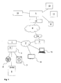
- the arrangement shown are the local network 2 with the house control unit 1 arranged as part of this local network 2, the IP-based public network 4 with the central server 5 and the NAT-capable access device 3, namely a router, via which the local network 2 the public network 4 is connectable to view.
- the Fig. 1 At the house control unit 1, a washing machine 7, a smart meter 8, so an intelligent electricity meter, and a cogeneration unit 9 (CHP) operated.
- CHP cogeneration unit 9
- a single-family house more network-enabled devices such as a modern TV 16 with a network card or a PC or laptop 15, be included.
- the home control unit 1 caused by a software or program application processed by its processing device, regularly transmits a presence message to the central server 5 in the public network 4 via the router 3.
- Part of this presence message is an identification feature, by which the house control unit concerned 1 is clearly identified.
- the corresponding identification feature is stored on a Trusted Platform Module installed in the home control unit 1 by the manufacturer and is read from this to the central server 5 for transmission of the presence message.
- the transmission of the presence message via a basically permanent existing, but in any case in the case of (for example, as a result of forced disconnection) interruption (at the latest in connection with the sending of the next presence message by the house control unit) rebuilt TCP / IP connection.
- the IP address of the central server 5, to which the presence messages are transmitted by suitable, arranged in the public network 4 (not shown here) facilities of the DNS system from one of the manufacturer of the house control unit 1 stored in this host name for the derived central server 5. Due to the cyclical transmission of the presence message, the central server 5 has information about the connection existing between the local network 2 and the server 5 at all times. The corresponding connection is made by the server 5 in a hash table of a database 6 in the form of a data record representing it at the socket level in association with the identification feature transmitted with the presence message under one for the operator of the local network or the accessibility to the House control unit wishing user stored account stored.
- the relevant database 6 may be a physical component of the central server 5 or may be in the form of a separate unit located in the access of the server 5.
- the server 5 For access to the house control unit 1, the server 5 transmits to this a connection request. After receiving this connection request, a tunnel connection to the server 5 is automatically established by the program application running in the home control unit 1 or processed by its processing unit. By using this tunnel connection, status information, commands and firmware updates for the house control unit can, if necessary after a previously performed authentication procedure 1 or operated on their devices safely, that is largely without accessibility by unauthorized third party, transferred.
- any tunneling protocols L2TP, PPP, IPSec and the like can be used for the provision of the tunnel.
- a semantic module 13 and a logging module 11 are also formed in or on this.
- the house control unit 1 by the central server 5 for the purpose of control or query status data of the operated with the house control unit 1 home devices 7, 8, 9 - here the washing machine 7, the smart meter 8 and the CHP 9-be addressed.
- the NAT-capable router 3 without requiring any intervention of the operator of the local area network 2, forwards corresponding data packets of the central server 5 using the NAT mechanism, more precisely the destination NAT (Destination Network Address Translation) to the House control unit 1 on.
- the central server 5 it is possible, for example, depending on the load of the public power grid via the central server 5 to run the powered on the house control unit 1 cogeneration unit 9 or turn off or query status data of the washing machine 7 or the smart meter 8.
- corresponding status data or states and signals which are received by the central control unit 5 from the home control unit 1 are interpreted by the semantic unit 13 and, if appropriate, causes the transmission of further control commands from the server 5 to the home control unit 1.
- the status data received at the central server 5 is stored for the purpose of the traceability for a specified period of time by the logging module 11 assigned to the central server 5.
- the current IP address of the local network 2 which is cyclically indirectly communicated by the home control unit 1 by sending the presence message can also be stored.
- the house control unit 1 in the Fig. 1 has a UMTS module 10 in order to ensure its permanent accessibility even in the event of a possible DSL failure.
- the operator of the local (non-public) network 2 or the operator of the home control unit 1 and / or third parties is enabled to access the home control unit 1 via the central server 5 by means of corresponding computer-based devices 12.
- the manufacturer of the house control unit 1 or the manufacturer of a device operated with this device 7, 8, 9 updates the firmware for the house control unit 1 and the device 7, 8, 9 transmit.
- the local network 2 and the public network 4 is, as already stated, preferably a wired connection.
- the local network 2 or its access device 3, namely the router is connected to the public network 4 via a DSL line.
- the transmission of data for the purpose of mutual authentication of home control unit 1 and server 5 can also be done using the SSL or TLS protocol.
- Such authentication may be required by the server if, for example, a forced disconnection of the DSL connection between the local network 2 and the public network 4 takes place at night and the server receives a presence message again for the first time after the connection has been restored.
- the central server 5 and the home control unit 1 mutually authenticate each other (mutual auth) according to a cryptographic authentication method.
- the house control unit 1 is equipped with an SSL client 1 '. Further data can then be unencrypted to reduce the effort be transmitted via a tunnel connection to the central server 5.
- the SSL connection referred to above is terminated on the server side by a security gateway 14 located upstream of the central server 5 from the perspective of the local network 2.
- the security gateway 14 takes over for the purpose of relieving the central server 5, the termination of the (possibly cryptographically secured) tunnel.
- communication takes place from the tunnel by means of simple stateless communication protocols, such as http (Hypertext Transfer Protocol), REST (Representational State Transfer), SOAP (Simple Object Access Protocol) or the like.
- FIG. 2 The diagram shown illustrates possible processes of the method according to the invention and the case between the house control unit 1 and the central server 5 each established or existing connections and is so far the possible operating states of the corresponding system again.
- Each constructed or existing compounds are shown in the diagram by arrows.
- Arrows with a solid line symbolize a basically permanent TCP / IP connection over which cyclically the presence message is transmitted from the house control unit 1 to the server 5, whereas the dashed line arrows a tunnel connection, that is a secure and authenticated connection symbolize.
- the connections as already stated, respectively between the house control unit 1 and the central server 5, which is illustrated by the parenthesized in the upper part of the drawing reference numerals of the relevant elements of the system.
- the access device 3 that is preferably via a router manufactured.
- the central server 5 basically at any time the current IP address of the access device 3 known. In any case, the server 5 but details about the connection are known, which allow him along with the running on the access device (the router) NAT access to the house control unit 1 and the transmission of a connection request to establish a tunnel connection to the house control unit 1.
- the access device 3 basically permanently existing TCP / IP connection, for example, by a nightly forced disconnection, is temporarily interrupted. Since the house control unit 1 transmits a presence message to the server 5 cyclically, that is to say with a time period stored in its configuration settings, the construction of a new connection to the server 5 is initiated at the latest by it shortly after the existence of such an interruption (a.1. ). As part of the construction of this connection to the public network 4, the access device 3 or the router receives a new public IP address (a.2.). Via this public IP address, the access device 3 and the private local network can be reached from an external point, such as by the central server 5.
- the connection established by the house control unit 1 to the server 5 exists as a fixed, unsecured connection (a.3.) And thereby represents a client-server connection, within the scope of which the home control unit 1 acts as a client with respect to the central server 5.
- b.1. to b.4 designated drain or system states
- the processes during the establishment of a secure connection between the house control unit 1 and the server 5 are symbolized, via which commands are transmitted to the home control unit 1, for example, from the server 5.
- the server 5 requests the house control unit 1 to set up a corresponding secure tunnel connection to the relevant commands to the house control unit 1 (b.1.).
- the request to set up the tunnel connection sent by the server 5 via the existing TCP / IP connection is symbolized by the solid line arrow directed to the home control unit 1.
- the house control unit 1 sets up a secure tunnel connection to the central server 5 and authenticates itself to it (b.2.).
- data can be transmitted or exchanged in both directions between the house control unit 1 and the central server 5 (b.3.), So that the server 5, as assumed above, for example, can transmit commands to the home control unit 1.
- the existing between the house control unit 1 and the central server 5 tunnel connection is then preferably, in particular if no data is transmitted over a longer period of time over this connection, terminated (b.4.). The latter is not mandatory.
- Designated states between the house control unit 1 and the central server 5 also a tunnel connection, the structure of which is initiated by the house control unit 1 itself, that is without appropriate request by the server 5 (c.1.).
- a corresponding situation can be given, for example, if in one of the house controllers 7, 8, 9 operated with the house control unit 1 (see Fig. 1 ) an operating state (an event) occurs in which the home control unit 1 transmits a corresponding message about the occurrence of this operating state to the server 5 on the basis of a rule stored in it.
- an operating state an event
- the tunnel connection is preferably degraded during longer non-activity (between the house control unit 1 and the central server 5 no data exchanged). According to d. In this case, however, the permanent TCP / IP connection between the home control unit 1 and the server 5 basically continues.
Landscapes
- Engineering & Computer Science (AREA)
- Computer Networks & Wireless Communication (AREA)
- Signal Processing (AREA)
- Automation & Control Theory (AREA)
- Computer Security & Cryptography (AREA)
- Computing Systems (AREA)
- Computer Hardware Design (AREA)
- General Engineering & Computer Science (AREA)
- Power Engineering (AREA)
- Data Exchanges In Wide-Area Networks (AREA)
- Small-Scale Networks (AREA)
Priority Applications (1)
| Application Number | Priority Date | Filing Date | Title |
|---|---|---|---|
| PL13075045T PL2680497T3 (pl) | 2012-06-28 | 2013-06-28 | Zewnętrzny dostęp do jednostki sterowania domem opartej na protokole IP w sieci lokalnej |
Applications Claiming Priority (1)
| Application Number | Priority Date | Filing Date | Title |
|---|---|---|---|
| DE102012105698A DE102012105698A1 (de) | 2012-06-28 | 2012-06-28 | Externer Zugriff auf IP-basierte Haussteuereinheit in lokalem Netzwerk |
Publications (2)
| Publication Number | Publication Date |
|---|---|
| EP2680497A1 true EP2680497A1 (fr) | 2014-01-01 |
| EP2680497B1 EP2680497B1 (fr) | 2015-04-01 |
Family
ID=48914039
Family Applications (1)
| Application Number | Title | Priority Date | Filing Date |
|---|---|---|---|
| EP13075045.8A Active EP2680497B1 (fr) | 2012-06-28 | 2013-06-28 | Accès externe à une unité de commande domestique basée sur IP dans un réseau local |
Country Status (4)
| Country | Link |
|---|---|
| EP (1) | EP2680497B1 (fr) |
| DE (1) | DE102012105698A1 (fr) |
| ES (1) | ES2537166T3 (fr) |
| PL (1) | PL2680497T3 (fr) |
Families Citing this family (4)
| Publication number | Priority date | Publication date | Assignee | Title |
|---|---|---|---|---|
| DE102014108657A1 (de) * | 2014-06-20 | 2015-12-24 | Eaton Industries Austria Gmbh | Schutzschaltgerät |
| FR3031260B1 (fr) * | 2014-12-24 | 2018-02-09 | Overkiz | Procede de transmission de donnees entre un serveur et une unite electronique de controle d’une installation domotique |
| DE102020114951A1 (de) | 2020-06-05 | 2021-12-09 | Westnetz Gmbh | Intelligentes Messsystem |
| CN113810897B (zh) * | 2020-06-11 | 2024-07-23 | 联发科技股份有限公司 | 用于接入npn的移动通信设备及方法 |
Citations (4)
| Publication number | Priority date | Publication date | Assignee | Title |
|---|---|---|---|---|
| EP1575230A1 (fr) * | 2002-11-29 | 2005-09-14 | Freebit Co., Ltd. | Serveur de routage d'une connexion vers un dispositif client |
| EP1978678A1 (fr) * | 2007-04-05 | 2008-10-08 | Deutsche Telekom AG | Accès externe à un réseau local doté d'une connexion Internet non permanente |
| WO2011053040A2 (fr) | 2009-11-02 | 2011-05-05 | Lg Electronics Inc. | Traversée de traducteur d'adresse réseau (nat) pour accès ip local |
| DE102009060469A1 (de) | 2009-12-22 | 2011-06-30 | eQ-3 AG, 26789 | Verfahren und Vorrichtung zur Sicherung der Kommunikation zwischen einem Heimautomatisierungsserver und einem zentralen Konfigurationsserver |
-
2012
- 2012-06-28 DE DE102012105698A patent/DE102012105698A1/de not_active Withdrawn
-
2013
- 2013-06-28 EP EP13075045.8A patent/EP2680497B1/fr active Active
- 2013-06-28 ES ES13075045.8T patent/ES2537166T3/es active Active
- 2013-06-28 PL PL13075045T patent/PL2680497T3/pl unknown
Patent Citations (4)
| Publication number | Priority date | Publication date | Assignee | Title |
|---|---|---|---|---|
| EP1575230A1 (fr) * | 2002-11-29 | 2005-09-14 | Freebit Co., Ltd. | Serveur de routage d'une connexion vers un dispositif client |
| EP1978678A1 (fr) * | 2007-04-05 | 2008-10-08 | Deutsche Telekom AG | Accès externe à un réseau local doté d'une connexion Internet non permanente |
| WO2011053040A2 (fr) | 2009-11-02 | 2011-05-05 | Lg Electronics Inc. | Traversée de traducteur d'adresse réseau (nat) pour accès ip local |
| DE102009060469A1 (de) | 2009-12-22 | 2011-06-30 | eQ-3 AG, 26789 | Verfahren und Vorrichtung zur Sicherung der Kommunikation zwischen einem Heimautomatisierungsserver und einem zentralen Konfigurationsserver |
Also Published As
| Publication number | Publication date |
|---|---|
| PL2680497T3 (pl) | 2015-09-30 |
| EP2680497B1 (fr) | 2015-04-01 |
| DE102012105698A1 (de) | 2013-10-31 |
| DE102012105698A8 (de) | 2014-01-02 |
| ES2537166T3 (es) | 2015-06-03 |
Similar Documents
| Publication | Publication Date | Title |
|---|---|---|
| EP2805208B1 (fr) | Procédé de communication de données entre un appareil ménager et un terminal utilisateur, appareil ménager et système comportant un appareil ménager et un terminal utilisateur | |
| DE60133241T2 (de) | Mehranwendung-sicherheitsrelais | |
| EP3066791B1 (fr) | Système de réseau, unité de couplage et procédé pour faire fonctionner un système de réseau | |
| EP3021524A1 (fr) | Procede de realisation d'un canal de commande local entre un appareil de commande et un portail d'acces interne au batiment | |
| EP2680497B1 (fr) | Accès externe à une unité de commande domestique basée sur IP dans un réseau local | |
| DE102012217144A1 (de) | Endgerät, Überwachungssystem mit dem Endgerät sowie Verfahren zur Initialisierung des Endgeräts in dem Überwachungssystem | |
| EP4335078B1 (fr) | Procédé de communication de noeuds iot ou d'appareils iot dans un réseau local | |
| DE60114186T2 (de) | Nachrichten-Vermittler | |
| EP2898649B1 (fr) | Système de surveillance avec transfert de messages, procédé et programme d'ordinateur | |
| DE112004000125T5 (de) | Gesichertes Client-Server-Datenübertragungssystem | |
| WO2007096249A1 (fr) | Procédé pour identifier de manière sûre la fin d'une session utilisateur | |
| WO2014086640A1 (fr) | Procédé, ensemble de traitement d'informations dans un appareil ménager ainsi qu'appareil ménager | |
| DE102021109193B4 (de) | Verfahren und systeme zur netzwerkadressen-übersetzung ( nat) unter verwendung eines meet-in-the-middle-proxys | |
| EP3697027B1 (fr) | Commande d'un appareil électroménager à l'aide d'un poste externe | |
| DE102020207033B4 (de) | Vorrichtungen und Verfahren zur Einbindung eines Geräts in ein Local Area Network | |
| DE102018105495B4 (de) | Verfahren und System zum Ermitteln einer Konfiguration einer Schnittstelle | |
| DE102021125836A1 (de) | Computernetzwerk für sichere ip-zu-nicht-ip-kommunikation und backend-gerät, gateway, frontend-gerät dafür und verfahren zu dessen betrieb | |
| EP2800342A1 (fr) | Procédé et système de gestion d'adresses IP dépendamment de l'état | |
| DE102024102645A1 (de) | Eigenverwaltung eines Heimnetzwerks über ein Weitverkehrsnetzwerk | |
| EP1496665B1 (fr) | Procédé de configuration de sécurité dans un réseau d'automatisation | |
| EP3094062B1 (fr) | Procédé de communication entre une unité de communication d'un appareil et une unité de communication externe par l'intermédiaire d'un système de téléphonie mobile | |
| WO2020065476A1 (fr) | Système et procédé d'accès à des données dans une zone interne | |
| DE602006000150T2 (de) | Verfahren und Gerät zur Zuordnung einer Kommunikationsvorrichtung zu einem Gateway | |
| DE102017108506A1 (de) | MIB-orientiertes Protokoll für hochwirksame http-Verwaltungsprozeduren | |
| DE102006054441A1 (de) | Verfahren und Geräte zum privaten Austauschen von Daten |
Legal Events
| Date | Code | Title | Description |
|---|---|---|---|
| PUAI | Public reference made under article 153(3) epc to a published international application that has entered the european phase |
Free format text: ORIGINAL CODE: 0009012 |
|
| AK | Designated contracting states |
Kind code of ref document: A1 Designated state(s): AL AT BE BG CH CY CZ DE DK EE ES FI FR GB GR HR HU IE IS IT LI LT LU LV MC MK MT NL NO PL PT RO RS SE SI SK SM TR |
|
| AX | Request for extension of the european patent |
Extension state: BA ME |
|
| RIN1 | Information on inventor provided before grant (corrected) |
Inventor name: KRAFT, ANDREAS |
|
| RIN1 | Information on inventor provided before grant (corrected) |
Inventor name: HELMUTH, VIVIEN Inventor name: KRAFT, ANDREAS Inventor name: GORGAS, DAGMAR Inventor name: MERRALL, SIMON Inventor name: SAYEGH, ANDREAS |
|
| RIN1 | Information on inventor provided before grant (corrected) |
Inventor name: KRAFT, ANDREAS Inventor name: GORGAS, DAGMAR Inventor name: HELMUT, VIVIEN Inventor name: SAYEGH, ANDREAS Inventor name: MERRALL, SIMON |
|
| 17P | Request for examination filed |
Effective date: 20140528 |
|
| RBV | Designated contracting states (corrected) |
Designated state(s): AL AT BE BG CH CY CZ DE DK EE ES FI FR GB GR HR HU IE IS IT LI LT LU LV MC MK MT NL NO PL PT RO RS SE SI SK SM TR |
|
| GRAP | Despatch of communication of intention to grant a patent |
Free format text: ORIGINAL CODE: EPIDOSNIGR1 |
|
| RIC1 | Information provided on ipc code assigned before grant |
Ipc: H04L 29/06 20060101ALI20141006BHEP Ipc: H04L 12/28 20060101AFI20141006BHEP |
|
| INTG | Intention to grant announced |
Effective date: 20141022 |
|
| GRAS | Grant fee paid |
Free format text: ORIGINAL CODE: EPIDOSNIGR3 |
|
| GRAA | (expected) grant |
Free format text: ORIGINAL CODE: 0009210 |
|
| AK | Designated contracting states |
Kind code of ref document: B1 Designated state(s): AL AT BE BG CH CY CZ DE DK EE ES FI FR GB GR HR HU IE IS IT LI LT LU LV MC MK MT NL NO PL PT RO RS SE SI SK SM TR |
|
| REG | Reference to a national code |
Ref country code: GB Ref legal event code: FG4D Free format text: NOT ENGLISH |
|
| REG | Reference to a national code |
Ref country code: CH Ref legal event code: EP |
|
| REG | Reference to a national code |
Ref country code: IE Ref legal event code: FG4D Free format text: LANGUAGE OF EP DOCUMENT: GERMAN |
|
| REG | Reference to a national code |
Ref country code: DE Ref legal event code: R096 Ref document number: 502013000496 Country of ref document: DE Effective date: 20150513 |
|
| REG | Reference to a national code |
Ref country code: AT Ref legal event code: REF Ref document number: 719655 Country of ref document: AT Kind code of ref document: T Effective date: 20150515 |
|
| REG | Reference to a national code |
Ref country code: CH Ref legal event code: NV Representative=s name: R.A. EGLI AND CO, PATENTANWAELTE, CH |
|
| REG | Reference to a national code |
Ref country code: ES Ref legal event code: FG2A Ref document number: 2537166 Country of ref document: ES Kind code of ref document: T3 Effective date: 20150603 |
|
| REG | Reference to a national code |
Ref country code: NL Ref legal event code: T3 |
|
| REG | Reference to a national code |
Ref country code: LT Ref legal event code: MG4D |
|
| REG | Reference to a national code |
Ref country code: PL Ref legal event code: T3 |
|
| REG | Reference to a national code |
Ref country code: SK Ref legal event code: T3 Ref document number: E 18926 Country of ref document: SK |
|
| PG25 | Lapsed in a contracting state [announced via postgrant information from national office to epo] |
Ref country code: LT Free format text: LAPSE BECAUSE OF FAILURE TO SUBMIT A TRANSLATION OF THE DESCRIPTION OR TO PAY THE FEE WITHIN THE PRESCRIBED TIME-LIMIT Effective date: 20150401 Ref country code: HR Free format text: LAPSE BECAUSE OF FAILURE TO SUBMIT A TRANSLATION OF THE DESCRIPTION OR TO PAY THE FEE WITHIN THE PRESCRIBED TIME-LIMIT Effective date: 20150401 Ref country code: FI Free format text: LAPSE BECAUSE OF FAILURE TO SUBMIT A TRANSLATION OF THE DESCRIPTION OR TO PAY THE FEE WITHIN THE PRESCRIBED TIME-LIMIT Effective date: 20150401 Ref country code: PT Free format text: LAPSE BECAUSE OF FAILURE TO SUBMIT A TRANSLATION OF THE DESCRIPTION OR TO PAY THE FEE WITHIN THE PRESCRIBED TIME-LIMIT Effective date: 20150803 Ref country code: NO Free format text: LAPSE BECAUSE OF FAILURE TO SUBMIT A TRANSLATION OF THE DESCRIPTION OR TO PAY THE FEE WITHIN THE PRESCRIBED TIME-LIMIT Effective date: 20150701 |
|
| PG25 | Lapsed in a contracting state [announced via postgrant information from national office to epo] |
Ref country code: LV Free format text: LAPSE BECAUSE OF FAILURE TO SUBMIT A TRANSLATION OF THE DESCRIPTION OR TO PAY THE FEE WITHIN THE PRESCRIBED TIME-LIMIT Effective date: 20150401 Ref country code: RS Free format text: LAPSE BECAUSE OF FAILURE TO SUBMIT A TRANSLATION OF THE DESCRIPTION OR TO PAY THE FEE WITHIN THE PRESCRIBED TIME-LIMIT Effective date: 20150401 Ref country code: GR Free format text: LAPSE BECAUSE OF FAILURE TO SUBMIT A TRANSLATION OF THE DESCRIPTION OR TO PAY THE FEE WITHIN THE PRESCRIBED TIME-LIMIT Effective date: 20150702 Ref country code: IS Free format text: LAPSE BECAUSE OF FAILURE TO SUBMIT A TRANSLATION OF THE DESCRIPTION OR TO PAY THE FEE WITHIN THE PRESCRIBED TIME-LIMIT Effective date: 20150801 |
|
| REG | Reference to a national code |
Ref country code: DE Ref legal event code: R097 Ref document number: 502013000496 Country of ref document: DE |
|
| PG25 | Lapsed in a contracting state [announced via postgrant information from national office to epo] |
Ref country code: EE Free format text: LAPSE BECAUSE OF FAILURE TO SUBMIT A TRANSLATION OF THE DESCRIPTION OR TO PAY THE FEE WITHIN THE PRESCRIBED TIME-LIMIT Effective date: 20150401 Ref country code: DK Free format text: LAPSE BECAUSE OF FAILURE TO SUBMIT A TRANSLATION OF THE DESCRIPTION OR TO PAY THE FEE WITHIN THE PRESCRIBED TIME-LIMIT Effective date: 20150401 Ref country code: MC Free format text: LAPSE BECAUSE OF FAILURE TO SUBMIT A TRANSLATION OF THE DESCRIPTION OR TO PAY THE FEE WITHIN THE PRESCRIBED TIME-LIMIT Effective date: 20150401 |
|
| PLBE | No opposition filed within time limit |
Free format text: ORIGINAL CODE: 0009261 |
|
| STAA | Information on the status of an ep patent application or granted ep patent |
Free format text: STATUS: NO OPPOSITION FILED WITHIN TIME LIMIT |
|
| PG25 | Lapsed in a contracting state [announced via postgrant information from national office to epo] |
Ref country code: RO Free format text: LAPSE BECAUSE OF NON-PAYMENT OF DUE FEES Effective date: 20150401 Ref country code: LU Free format text: LAPSE BECAUSE OF FAILURE TO SUBMIT A TRANSLATION OF THE DESCRIPTION OR TO PAY THE FEE WITHIN THE PRESCRIBED TIME-LIMIT Effective date: 20150628 |
|
| 26N | No opposition filed |
Effective date: 20160105 |
|
| REG | Reference to a national code |
Ref country code: IE Ref legal event code: MM4A |
|
| PG25 | Lapsed in a contracting state [announced via postgrant information from national office to epo] |
Ref country code: IE Free format text: LAPSE BECAUSE OF NON-PAYMENT OF DUE FEES Effective date: 20150628 |
|
| PG25 | Lapsed in a contracting state [announced via postgrant information from national office to epo] |
Ref country code: SI Free format text: LAPSE BECAUSE OF FAILURE TO SUBMIT A TRANSLATION OF THE DESCRIPTION OR TO PAY THE FEE WITHIN THE PRESCRIBED TIME-LIMIT Effective date: 20150401 |
|
| REG | Reference to a national code |
Ref country code: FR Ref legal event code: PLFP Year of fee payment: 4 |
|
| PG25 | Lapsed in a contracting state [announced via postgrant information from national office to epo] |
Ref country code: MT Free format text: LAPSE BECAUSE OF FAILURE TO SUBMIT A TRANSLATION OF THE DESCRIPTION OR TO PAY THE FEE WITHIN THE PRESCRIBED TIME-LIMIT Effective date: 20150401 |
|
| PG25 | Lapsed in a contracting state [announced via postgrant information from national office to epo] |
Ref country code: HU Free format text: LAPSE BECAUSE OF FAILURE TO SUBMIT A TRANSLATION OF THE DESCRIPTION OR TO PAY THE FEE WITHIN THE PRESCRIBED TIME-LIMIT; INVALID AB INITIO Effective date: 20130628 Ref country code: BG Free format text: LAPSE BECAUSE OF FAILURE TO SUBMIT A TRANSLATION OF THE DESCRIPTION OR TO PAY THE FEE WITHIN THE PRESCRIBED TIME-LIMIT Effective date: 20150401 |
|
| REG | Reference to a national code |
Ref country code: FR Ref legal event code: PLFP Year of fee payment: 5 |
|
| PG25 | Lapsed in a contracting state [announced via postgrant information from national office to epo] |
Ref country code: CY Free format text: LAPSE BECAUSE OF FAILURE TO SUBMIT A TRANSLATION OF THE DESCRIPTION OR TO PAY THE FEE WITHIN THE PRESCRIBED TIME-LIMIT Effective date: 20150401 Ref country code: SE Free format text: LAPSE BECAUSE OF FAILURE TO SUBMIT A TRANSLATION OF THE DESCRIPTION OR TO PAY THE FEE WITHIN THE PRESCRIBED TIME-LIMIT Effective date: 20150401 |
|
| PG25 | Lapsed in a contracting state [announced via postgrant information from national office to epo] |
Ref country code: BE Free format text: LAPSE BECAUSE OF NON-PAYMENT OF DUE FEES Effective date: 20150630 |
|
| PG25 | Lapsed in a contracting state [announced via postgrant information from national office to epo] |
Ref country code: TR Free format text: LAPSE BECAUSE OF FAILURE TO SUBMIT A TRANSLATION OF THE DESCRIPTION OR TO PAY THE FEE WITHIN THE PRESCRIBED TIME-LIMIT Effective date: 20150401 |
|
| PG25 | Lapsed in a contracting state [announced via postgrant information from national office to epo] |
Ref country code: SM Free format text: LAPSE BECAUSE OF FAILURE TO SUBMIT A TRANSLATION OF THE DESCRIPTION OR TO PAY THE FEE WITHIN THE PRESCRIBED TIME-LIMIT Effective date: 20150401 |
|
| REG | Reference to a national code |
Ref country code: FR Ref legal event code: PLFP Year of fee payment: 6 |
|
| PG25 | Lapsed in a contracting state [announced via postgrant information from national office to epo] |
Ref country code: MK Free format text: LAPSE BECAUSE OF FAILURE TO SUBMIT A TRANSLATION OF THE DESCRIPTION OR TO PAY THE FEE WITHIN THE PRESCRIBED TIME-LIMIT Effective date: 20150401 |
|
| PG25 | Lapsed in a contracting state [announced via postgrant information from national office to epo] |
Ref country code: AL Free format text: LAPSE BECAUSE OF FAILURE TO SUBMIT A TRANSLATION OF THE DESCRIPTION OR TO PAY THE FEE WITHIN THE PRESCRIBED TIME-LIMIT Effective date: 20150401 |
|
| REG | Reference to a national code |
Ref country code: DE Ref legal event code: R082 Ref document number: 502013000496 Country of ref document: DE Representative=s name: MAUCHER JENKINS PATENTANWAELTE & RECHTSANWAELT, DE |
|
| PGFP | Annual fee paid to national office [announced via postgrant information from national office to epo] |
Ref country code: PL Payment date: 20250616 Year of fee payment: 13 Ref country code: DE Payment date: 20250618 Year of fee payment: 13 |
|
| PGFP | Annual fee paid to national office [announced via postgrant information from national office to epo] |
Ref country code: GB Payment date: 20250620 Year of fee payment: 13 |
|
| PGFP | Annual fee paid to national office [announced via postgrant information from national office to epo] |
Ref country code: NL Payment date: 20250618 Year of fee payment: 13 |
|
| PGFP | Annual fee paid to national office [announced via postgrant information from national office to epo] |
Ref country code: FR Payment date: 20250626 Year of fee payment: 13 |
|
| PGFP | Annual fee paid to national office [announced via postgrant information from national office to epo] |
Ref country code: AT Payment date: 20250616 Year of fee payment: 13 |
|
| PGFP | Annual fee paid to national office [announced via postgrant information from national office to epo] |
Ref country code: SK Payment date: 20250624 Year of fee payment: 13 |
|
| PGFP | Annual fee paid to national office [announced via postgrant information from national office to epo] |
Ref country code: CZ Payment date: 20250613 Year of fee payment: 13 |
|
| PGFP | Annual fee paid to national office [announced via postgrant information from national office to epo] |
Ref country code: ES Payment date: 20250718 Year of fee payment: 13 |
|
| PGFP | Annual fee paid to national office [announced via postgrant information from national office to epo] |
Ref country code: IT Payment date: 20250630 Year of fee payment: 13 |
|
| PGFP | Annual fee paid to national office [announced via postgrant information from national office to epo] |
Ref country code: CH Payment date: 20250701 Year of fee payment: 13 |