EP2680898B1 - Dispositif d'insertion à ressort compact pour tubulure de perfusion d'administration de médicament - Google Patents
Dispositif d'insertion à ressort compact pour tubulure de perfusion d'administration de médicament Download PDFInfo
- Publication number
- EP2680898B1 EP2680898B1 EP12770720.6A EP12770720A EP2680898B1 EP 2680898 B1 EP2680898 B1 EP 2680898B1 EP 12770720 A EP12770720 A EP 12770720A EP 2680898 B1 EP2680898 B1 EP 2680898B1
- Authority
- EP
- European Patent Office
- Prior art keywords
- catheter
- base
- inserter
- introducer needle
- infusion set
- Prior art date
- Legal status (The legal status is an assumption and is not a legal conclusion. Google has not performed a legal analysis and makes no representation as to the accuracy of the status listed.)
- Active
Links
Images


Classifications
-
- A—HUMAN NECESSITIES
- A61—MEDICAL OR VETERINARY SCIENCE; HYGIENE
- A61M—DEVICES FOR INTRODUCING MEDIA INTO, OR ONTO, THE BODY; DEVICES FOR TRANSDUCING BODY MEDIA OR FOR TAKING MEDIA FROM THE BODY; DEVICES FOR PRODUCING OR ENDING SLEEP OR STUPOR
- A61M25/00—Catheters; Hollow probes
- A61M25/01—Introducing, guiding, advancing, emplacing or holding catheters
- A61M25/06—Body-piercing guide needles or the like
- A61M25/0606—"Over-the-needle" catheter assemblies, e.g. I.V. catheters
-
- A—HUMAN NECESSITIES
- A61—MEDICAL OR VETERINARY SCIENCE; HYGIENE
- A61M—DEVICES FOR INTRODUCING MEDIA INTO, OR ONTO, THE BODY; DEVICES FOR TRANSDUCING BODY MEDIA OR FOR TAKING MEDIA FROM THE BODY; DEVICES FOR PRODUCING OR ENDING SLEEP OR STUPOR
- A61M5/00—Devices for bringing media into the body in a subcutaneous, intra-vascular or intramuscular way; Accessories therefor, e.g. filling or cleaning devices, arm-rests
- A61M5/14—Infusion devices, e.g. infusing by gravity; Blood infusion; Accessories therefor
- A61M5/158—Needles for infusions; Accessories therefor, e.g. for inserting infusion needles, or for holding them on the body
-
- A—HUMAN NECESSITIES
- A61—MEDICAL OR VETERINARY SCIENCE; HYGIENE
- A61M—DEVICES FOR INTRODUCING MEDIA INTO, OR ONTO, THE BODY; DEVICES FOR TRANSDUCING BODY MEDIA OR FOR TAKING MEDIA FROM THE BODY; DEVICES FOR PRODUCING OR ENDING SLEEP OR STUPOR
- A61M5/00—Devices for bringing media into the body in a subcutaneous, intra-vascular or intramuscular way; Accessories therefor, e.g. filling or cleaning devices, arm-rests
- A61M5/14—Infusion devices, e.g. infusing by gravity; Blood infusion; Accessories therefor
- A61M5/158—Needles for infusions; Accessories therefor, e.g. for inserting infusion needles, or for holding them on the body
- A61M2005/1581—Right-angle needle-type devices
-
- A—HUMAN NECESSITIES
- A61—MEDICAL OR VETERINARY SCIENCE; HYGIENE
- A61M—DEVICES FOR INTRODUCING MEDIA INTO, OR ONTO, THE BODY; DEVICES FOR TRANSDUCING BODY MEDIA OR FOR TAKING MEDIA FROM THE BODY; DEVICES FOR PRODUCING OR ENDING SLEEP OR STUPOR
- A61M5/00—Devices for bringing media into the body in a subcutaneous, intra-vascular or intramuscular way; Accessories therefor, e.g. filling or cleaning devices, arm-rests
- A61M5/14—Infusion devices, e.g. infusing by gravity; Blood infusion; Accessories therefor
- A61M5/158—Needles for infusions; Accessories therefor, e.g. for inserting infusion needles, or for holding them on the body
- A61M2005/1585—Needle inserters
-
- A—HUMAN NECESSITIES
- A61—MEDICAL OR VETERINARY SCIENCE; HYGIENE
- A61M—DEVICES FOR INTRODUCING MEDIA INTO, OR ONTO, THE BODY; DEVICES FOR TRANSDUCING BODY MEDIA OR FOR TAKING MEDIA FROM THE BODY; DEVICES FOR PRODUCING OR ENDING SLEEP OR STUPOR
- A61M5/00—Devices for bringing media into the body in a subcutaneous, intra-vascular or intramuscular way; Accessories therefor, e.g. filling or cleaning devices, arm-rests
- A61M5/14—Infusion devices, e.g. infusing by gravity; Blood infusion; Accessories therefor
- A61M5/158—Needles for infusions; Accessories therefor, e.g. for inserting infusion needles, or for holding them on the body
- A61M2005/1586—Holding accessories for holding infusion needles on the body
-
- A—HUMAN NECESSITIES
- A61—MEDICAL OR VETERINARY SCIENCE; HYGIENE
- A61M—DEVICES FOR INTRODUCING MEDIA INTO, OR ONTO, THE BODY; DEVICES FOR TRANSDUCING BODY MEDIA OR FOR TAKING MEDIA FROM THE BODY; DEVICES FOR PRODUCING OR ENDING SLEEP OR STUPOR
- A61M5/00—Devices for bringing media into the body in a subcutaneous, intra-vascular or intramuscular way; Accessories therefor, e.g. filling or cleaning devices, arm-rests
- A61M5/14—Infusion devices, e.g. infusing by gravity; Blood infusion; Accessories therefor
- A61M5/158—Needles for infusions; Accessories therefor, e.g. for inserting infusion needles, or for holding them on the body
- A61M2005/1587—Needles for infusions; Accessories therefor, e.g. for inserting infusion needles, or for holding them on the body suitable for being connected to an infusion line after insertion into a patient
Definitions
- the present invention relates generally to a compact spring inserter for a drug delivery infusion set. More particularly, the present invention relates to an inserter in which a spring member is stored in a base of an infusion set after inserting an introducer needle and a catheter. Still more particularly, the present invention relates to an inserter in which insertion of an introducer needle and catheter at an insertion site is actuated by the rotation of a dial or outer housing.
- the first mode includes syringes and insulin pens. These devices are simple to use and are relatively low in cost, but they require a needle stick at each injection, typically three to four times per day.
- the second mode includes infusion pump therapy, which entails the purchase of an insulin pump that lasts for about three years. The initial cost of the pump can be significant, but is superior from a user perspective. Consequently, the overwhelming majority of patients who have used pumps prefer to remain with pumps for the rest of their lives. Infusion pumps, although more complex than syringes and pens, offer the advantages of continuous infusion of insulin, precision dosing and programmable delivery schedules. This results in closer blood glucose control and an improved feeling of wellness.
- an infusion pump requires the use of a disposable component, typically referred to as an infusion set or pump set, which conveys the insulin from a reservoir within the pump into the skin of the user.
- An infusion set typically consists of a pump connector, a length of tubing, and a hub or base from which an infusion cannula extends.
- the hub or base has an adhesive that retains the base on the skin surface during use, and may be applied to the skin manually or with the aid of a manual or automatic insertion device.
- infusion sets including steel needle infusion sets and soft catheter sets.
- Soft catheter sets are typically inserted into a patient manually with the aid of a steel needle introducer, which is manually removed from the patient after insertion to leave the soft catheter in place.
- One problem associated with manually inserting and retracting the introducer needle is variability in the insertion and retraction force, speed, smoothness and angle. This variability can lead to an increased rate of catheter insertion failure. Further, as noted above, the user typically must remove the introducer needle after inserting the catheter. This exposes the user to accidental needle sticks from handling the removed introducer needle.
- a mechanized insertion device is used to forcefully and rapidly insert the introducer needle and catheter, remove the introducer, or both.
- the insertion device is a separate, stand-alone unit that the user is required to carry and provide.
- Stand-alone inserters typically require the user to manually load a spring of the inserter, which can result in catheter insertion failure when the spring is not properly loaded.
- WO 2006/077262 A1 discloses a medical device comprising a first and a second unit. When an actuation device or button is pressed, the medical device, a first spring is released to power lower and upper members towards a base plate, to insert an insertion needle of the upper member and the catheter of the lower member. The lower member is then coupled to the coupling member of the base plate, as a second is biased, and the first spring retracts the upper member as well as the insertion needle.
- An object of the present invention is to provide a compact spring inserter for an infusion set, particularly an insulin infusion set.
- Another object of the present invention is to provide an infusion set inserter in which a spring member is used to facilitate catheter insertion and is stored in the base of the infusion set after insertion, thereby substantially preventing catheter insertion failure and providing a low profile infusion set.
- Another object of the present invention is to provide an infusion set in which a connector of the infusion set connects directly to a catheter hub, thereby reducing the number of components in the fluid path.
- a drug delivery infusion set houses and stores a spring member that inserts an introducer needle and a catheter at an insertion site.
- the catheter and introducer needle are inserted from a vertical position of the inserter by rotating an outer housing serving as a dial.
- the introducer needle is manually removed from the insertion site by disconnecting the inserter from a base.
- the spring member is stored in the base, allowing the thickness of the infusion set to be reduced.
- a knob on the inserter withdraws the introducer needle into the housing or dial to shield the introducer needle, thereby substantially preventing accidental introducer needle sticks.
- the introducer needle is not part of the fluid path, thereby reducing the number of components in the fluid path and substantially preventing leakage and sealing problems.
- an infusion set including a base and an inserter removably connected to the base.
- a catheter is movable from a first catheter position disposed substantially entirely within the inserter to a second catheter position in which a free end of the catheter is disposed externally of the base.
- An introducer needle is located within the catheter and is movable with the catheter between a first introducer needle position disposed substantially entirely within the inserter and a second introducer needle position in which a free end of the introducer needle is disposed externally of the base.
- a spring member moves the catheter from the first to the second catheter position and the introducer needle from the first to the second introducer needle position to facilitate insertion of the catheter.
- the spring member is disposed substantially entirely within the base when the catheter is in the second catheter position.
- an infusion set having a removable inserter that stores a spring member in a base and withdraws an introducer needle of the infusion set, thereby providing a low profile infusion set. Additionally, accidental introducer needle sticks are substantially prevented by disposing the introducer needle within the removed inserter.
- the exemplary embodiment of the present invention described below provides a novel means of inserting a soft catheter into the skin.
- the exemplary embodiment of the present invention provides an inserter 121 that inserts an introducer needle 142 and a soft catheter 134 into the skin, and then stores a spring member 171 in a base 111 of an infusion set 101, as shown in FIGS. 2 , 3 , 10 and 14 , thereby providing a low profile infusion set.
- the base 111 of the infusion set is preferably provided with a skin-securing, adhesive layer 112, as shown in FIGS. 2 and 3 , to secure the infusion set to the skin surface at the insertion site.
- the adhesive layer 112 ensures that the base remains at the proper position relative to the skin surface, and that the skin is secured during insertion to further aid introducer needle insertion with a reduced risk of tenting of the skin surface.
- the base 111 has a planar surface 113 having an opening 114 therein through which the catheter 134 and the introducer needle 142 pass, as shown in FIGS. 4 , 10 and 11 .
- a wall 115 extends upwardly from an outer edge of the planar surface 113 such that a cavity 116 is defined by the planar surface and the wall 115, as shown in FIG. 4 .
- the inserter 121 includes a housing or dial 123 rotatably connected to the base 111, a dial post 124 extending upwardly from a base 122 of the dial 123, and a knob 125 movably connected to the dial post 124, as shown in FIGS. 2 , 4 and 10 .
- the dial 123 has a substantially frustoconical shape, as shown in FIGS. 2 and 4 .
- a wall 126 of the dial 123 extends downwardly and outwardly from the dial base 122 and the dial post 124 extends upwardly from and substantially perpendicularly to the dial base 122.
- the dial post 124 comprises three substantially arcuate members 181, 182 and 183 spaced apart from one another at an upper end thereof, as shown in FIG.
- First and second arms 191 and 193 extend downwardly from the dial base 122 and are disposed within the dial wall 126.
- First and second shoulders 192 and 194 are formed on the first and second arms 191 and 193, respectively, as shown in FIG. 6 .
- Slots 197 and 198 are formed between the first and second arms 191 and 193, as shown in FIGS. 4 - 6 .
- the slots 197 and 198 allow for downward movement of the catheter hub 131.
- Hooks 117 and 118 connected to the arms 191 and 193, as shown in FIGS. 11 and 15 are received by the base 111.
- the hooks 117 and 118 engage a lower surface 132 of the base 111, as shown in FIG. 11 , to prevent withdrawal of the dial 121 prior to insertion of the catheter 134.
- the inserter knob 125 is movable between a first, or up, position, as shown in FIG. 4 , and a second, or down, position as shown in FIG. 12 .
- the inserter knob 125 is rigidly fixed to an end of an introducer needle plunger 141.
- the introducer needle 142 is disposed within the dial 123.
- the knob 125 is in the second position as shown in FIG. 10 , the introducer needle 142 is exposed outside the dial 123.
- the catheter hub 131 is initially disposed in a first position inside the dial 123, as shown in FIGS. 4 and 5 .
- the catheter hub 131 has an inner ring 133 and an outer ring 135 connected by first and second connecting arms 136 and 137.
- first and second connecting arms 136 and 137 rest on the shoulders 192 and 194 of the arms 191 and 193 of the dial as shown in FIG. 5 , thereby preventing downward (toward the base 111) movement of the catheter hub 131.
- a soft catheter 134 extends downwardly from the inner ring 133 of the catheter hub 131.
- An opening 138 is disposed in the inner ring 133 of the catheter hub 131 to allow the introducer needle 142 to pass therethrough, as shown in FIG. 4 .
- a septum 172 is disposed inside a recess formed in the inner ring 133 of the catheter hub 131, as shown in FIGS. 4 and 14 .
- a spring member 171 is disposed within the dial 123, as shown in FIG. 4 .
- a first end 173 of the spring member 171 is connected to the catheter hub 131.
- a second end 174 of the spring member 171 is connected to the base 111.
- the spring member 171 is a volute extension spring such that each subsequent coil of the spring member from the first end 173 to the second end 174 has a larger diameter.
- a volute spring is a compression spring that is typically substantially cone-shaped. When the volute spring is under compression the coils are not forced against each other, but instead nest within each other, thus permitting longer travel and increased compactness in the compressed configuration. As shown in FIG.
- the spring member 171 is initially in tension with the catheter hub 131 resting on the shoulders 192 and 194 of the arms 191 and 193 to prevent downward movement of the catheter hub 131.
- the spring member 171 collapses, thereby pulling the catheter 134 and the introducer needle 142 into the insertion site.
- the spring member 171 collapses upon itself forming a substantially disc-shaped member having a low profile that is substantially entirely received within the cavity 116 in the base 111.
- the introducer needle plunger 141 has a first end 143 and a second end 145, as shown in FIG. 4 .
- the first end 143 is rigidly connected to the knob 125, such that the knob moves with the plunger 141.
- the introducer needle 142 is rigidly connected to the second end 145 such that the introducer moves with movement of the plunger 141.
- the plunger 141 moves within the dial post 124 for movement external of the dial 123 and within the arms 191 and 193 for movement within the dial 123.
- the plunger 141 is movable from a first position shown in FIG. 4 , to a second position shown in FIG. 12 and back to the first position.
- First and second plunger arms 146 and 147 have hooks 148 and 149, as shown in FIGS.
- Recesses 185 and 186 in the outer circumference of the catheter hub 131 allow for the plunger 141 to be disengaged from the catheter hub after the catheter 134 has been inserted.
- the introducer needle 142 passes through the septum 172 and through the catheter 134 such that an end 144 of the introducer needle is exposed outside of the catheter 134, as shown in FIGS. 7 , 10 and 11 , when the catheter hub 131 is in the second position.
- the end 144 of the introducer needle end 142 is sharp to facilitate piercing the skin at a desired catheter insertion point.
- the plunger 141 is in the first position ( FIG. 4 )
- the introducer needle 142 is not exposed outside the dial 123.
- the plunger 141 is in the second position ( FIG. 12 )
- the introducer needle 142 is exposed externally of the dial 123 and the base 111 such that the introducer needle can pierce the skin at the desired catheter insertion point.
- a locking member 161 is rotationally disposed in the base 111, as shown in FIG. 4 .
- Snap arms 106 and 107 connected to the base 111, as shown in FIGS. 8, 9 and 11 have hooks 108 and 109 that are received in recesses 162 of the locking member 161, as shown in FIG. 9 , to prevent rotation of the locking member 161 with respect to the base 111 prior to insertion of the catheter 134.
- the snap arms 106 and 107 are moved downwardly by the catheter hub 131 during insertion such that the hooks 108 and 109 are moved out of the recesses 162, as shown in FIGS. 8 and 9 , thereby allowing the locking member 161 to rotate.
- the locking member 161 has overhangs 164 and 165 that are rotated after insertion of the catheter 134 that rotate over the catheter hub 131, as shown in FIG. 14 , thereby locking the catheter hub 131 to the base 111.
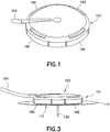
- a connector 103 has a plurality of flexible arms 195 adapted to engage the corresponding recesses 196 in the outer surface of the base 111, as shown in FIGS. 1 - 3 .
- Tubing 104 extends from the connector 103 and is adapted to connect to a pump.
- the tubing 104 is connected to a penetrating member, or sharp (not shown), extending downwardly from the connector 103, and a fluid path is formed therebetween.
- the penetrating member is adapted to penetrate the septum 172 when the connector 103 is connected to the base 111, as shown in FIG. 3 , thereby creating a fluid path between the tubing 104 and the catheter 134.
- FIG. 2 is a perspective view of the base 111 and inserter 121 as received by the user.
- the hooks 117 and 118 of the inserter 121 engage the lower surface 132 of the base 111, as shown in FIG. 11 , thereby preventing the inserter 121 from being removed from the base.
- the knob 125 is in the first, or up, position, as shown in FIG. 2 , such that the catheter 134 and the introducer needle 142 are substantially entirely disposed within the dial body 123, as shown in FIG. 2 , thereby substantially preventing accidental introducer needle sticks.
- the connector 103 ( FIG. 1 ) is not yet connected to the base 111 because the catheter 134 has not yet been inserted.
- the spring member 171 is in tension, as shown in FIG. 4 .
- a backing (not shown) is removed to expose an adhesive layer 112 so that the base 111 can be adhered to the skin surface at the desired catheter insertion site.
- the catheter hub 131 rests on the shoulders 192 and 194 of the dial arms 191 and 193, thereby preventing downward movement of the catheter hub 131.
- the dial 123 is rotated clockwise.
- the adhesive layer 112 provides a counter-rotation force to resist movement of the base 111 when the dial 123 is rotated.
- the rotation of the dial 123 causes the dial arms 191 and 193 to rotate, thereby moving the shoulders 192 and 194 of the dial arms 191 and 193 out of engagement with the catheter hub 131, as shown in FIG. 6 .
- the catheter hub arms 136 and 137 are now aligned with the slots 197 and 198 between the base arms 191 and 193, such that the stored energy in the stretched spring member 171 pulls the catheter hub 131 downwardly (i.e., toward the base 111).
- the slots 197 and 198 guide the catheter hub 131 through its downward movement to the base 111.
- the catheter 134 is rigidly connected to the catheter hub 131 so that the catheter 134 is pulled downwardly with the catheter hub 131.
- the plunger hooks 148 and 149 engage the catheter hub 131 so that the introducer needle 142, which is rigidly connected to the plunger 141, is also pulled downwardly with the catheter hub 131.
- knob 125 which is connected to the first end 143 of the plunger 141, is pulled downwardly along the dial post 124, as shown in FIG. 10 .
- the movement of the knob 125 to the second, or down, position indicates to the user that the introducer needle 142 and catheter 134 have been inserted.
- the hooks 108 and 109 of the snap arms 106 and 107 of the base 111 are received in recesses 162 in the locking member 161 prior to insertion of the introducer needle 142 and catheter 134, thereby preventing movement of the locking member 161.
- Tabs 178 and 179 extending radially inwardly from the locking member 161 engage hooks 117 and 118 of the dial 123, as shown in FIG. 11 , thereby preventing further rotation, and hence withdrawal, of the dial prior to the catheter 134 and introducer needle 142 being inserted.
- the spring member 171 pulls the catheter hub 131 into the cavity 116 in the base 111, the catheter hub 131 engages the base snap arms 106 and 107 and pushes them downwardly, as shown in FIGS.
- the dial 123 can now be further rotated clockwise. Rotation of the dial hooks 117 and 118 causes rotation of the locking member tabs 178 and 179.
- the rotation of the locking member 161 causes the base snap arms 106 and 107 to slide along ramps 175 and 176 on the outer surface of the locking member and into locking recesses 177 and 180, as shown in FIGS. 9 and 11 .
- the rotation of the locking member 161 also causes the locking member overhangs 164 and 165 to rotate over the catheter hub 131, as shown in FIG. 12 , thereby locking the catheter hub 131 to the base 111.
- the rotation of the dial 123 moves the hooks 117 and 118 to engage recesses 185 and 186 in the base 111, as shown in FIG. 11 .
- the plunger hooks 148 and 149 are also rotated by rotation of the dial 123 to engage recesses 154 and 155 in the catheter hub 131. Accordingly, the inserter 121, including the dial 123 and plunger 141, can be removed from the base 111, as shown in FIGS. 14 and 15 .
- the spring member 171, catheter hub 131 and locking member 161 remain in the base 111, as shown in FIG. 14 , such that the catheter 134 remains inserted in the insertion site and the introducer needle 142 is withdrawn from the insertion site.
- the septum 172 in the catheter hub 131 is now exposed, as shown in FIG. 14 .
- the soft catheter 134 remains inserted below the skin and in a substantially vertical position after the dial 123 has been rotated and removed from the base 111, i.e., the soft catheter 134 does not bend with the rotational movement of the dial 123. Accordingly, piercing the septum 172 provides a direct fluid path to the soft catheter 134 as the introducer needle 142 is not part of the fluid path.
- a penetrating member, or sharp (not shown), on the fluid connector 103 can now penetrate the septum 172, thereby creating a fluid connection between the catheter 134 and the tubing 104.
- the user can prime the connector 103 prior to connecting it to the infusion set base 111.
- Flexible arms 195 of the connector 103 engage recesses 196 in the base 111 to removably connect the connector 103 to the base 111.
- the infusion set 101 as shown in FIGS. 1 and 3 , is now ready to begin infusing insulin.
- the connector 103 can be removed and reattached to the infusion set base 111 at any time by disengaging and connecting the flexible arms 195 with the base recesses 196.
- the septum 172 provides a sterility barrier when the penetrating member is removed therefrom, and the fluid connection is reestablished by reinserting the penetrating member through the septum 172 located in the catheter hub 131, which is secured by the locking member 161 in the base 111.
- the knob 125 of the removed inserter 121 is moved back to the first, or up position, as shown in FIG. 15 , thereby lifting the plunger 141 and withdrawing the introducer needle 141 to a protected position within the housing or dial 123. As shown in FIGS. 4 , 15 and 16 , the knob 125 is lifted until the recess 157 in the plunger 141 engages the hook 158 of the dial 123. The dial hook 158 engages the plunger recess 157, thereby preventing downward movement of the plunger 141 and substantially preventing accidental introducer needle sticks.
- the exemplary embodiment described above can be adapted for use with either subcutaneous or intradermal injections.
- a different method of maintaining the fluid connection which is not part of the invention, is possible other than through the penetrating member 197 and septum 172.
- a sliding gasket seal can be used.
- Alternative methods which are not disclosed by the invention, can be used to insert the catheter and introducer.
- an angled needle in contact with the skin and driven horizontally can be used to enter the subcutaneous or intradermal layers of the skin.
- Alternative methods of connecting the connector to the base can be used to facilitate connecting and disconnecting of the connector.
- a ramped surface 159 as shown in FIGS.
- the introducer needle 142 can be withdrawn from the insertion site and stored in the base 111 after inserting the catheter 134 instead of being withdrawn from the base with the inserter 121.
Landscapes
- Health & Medical Sciences (AREA)
- Life Sciences & Earth Sciences (AREA)
- Animal Behavior & Ethology (AREA)
- General Health & Medical Sciences (AREA)
- Biomedical Technology (AREA)
- Heart & Thoracic Surgery (AREA)
- Hematology (AREA)
- Engineering & Computer Science (AREA)
- Veterinary Medicine (AREA)
- Anesthesiology (AREA)
- Public Health (AREA)
- Vascular Medicine (AREA)
- Biophysics (AREA)
- Pulmonology (AREA)
- Infusion, Injection, And Reservoir Apparatuses (AREA)
- Media Introduction/Drainage Providing Device (AREA)
Claims (8)
- Ensemble de perfusion (101), comprenant :une base (111) ;un dispositif d'insertion (121) relié de manière amovible à ladite base (111) ;un cathéter (134) mobile d'une première position de cathéter disposée à l'intérieur dudit dispositif d'insertion (121) à une deuxième position de cathéter dans laquelle une extrémité libre dudit cathéter (134) est disposée à l'extérieur de ladite base (111) ;une aiguille d'introduction (142) située à l'intérieur dudit cathéter (134) et mobile avec ledit cathéter (134) entre une première position d'aiguille d'introduction (142) disposée à l'intérieur dudit dispositif d'insertion (121) et une deuxième position d'aiguille d'introduction (142) dans laquelle une extrémité libre de ladite aiguille d'introduction (142) est disposée à l'extérieur de ladite base (111) ; etun élément de ressort (171) pour déplacer ledit cathéter (134) de ladite première à ladite deuxième position de cathéter et ladite aiguille d'introduction (142) de ladite première à ladite deuxième position d'aiguille d'introduction pour faciliter l'insertion dudit cathéter (134), ledit élément de ressort (171) étant disposé à l'intérieur de ladite base (111) lorsque ledit cathéter (134) se trouve dans ladite deuxième position de cathéter ;caractérisé en ce que ledit élément de ressort (171) peut être activé en faisant tourner ledit dispositif d'insertion (121),dans lequel ledit cathéter (134) est relié à un embout de cathéter (131), ledit embout de cathéter (131) étant mobile avec ledit cathéter (134) entre lesdites première et deuxième positions de cathéter,dans lequel ledit embout de cathéter (131) s'engage avec un épaulement interne dudit dispositif d'insertion (121) pour retenir ledit embout de cathéter (131) dans ladite première position d'embout de cathéter, etdans lequel la rotation dudit dispositif d'insertion (121) désengage ledit épaulement interne (192) dudit dispositif d'insertion (121) dudit embout de cathéter (131) de sorte que ledit élément de ressort (171) déplace ledit embout de cathéter (131) vers ladite deuxième position de cathéter.
- Ensemble de perfusion (101) selon la revendication 1, dans lequel un piston (141) est relié de manière amovible audit embout de cathéter (131) ; et
ladite aiguille d'introduction (142) est reliée rigidement audit piston (141). - Ensemble de perfusion (101) selon la revendication 2, dans lequel une première extrémité dudit élément de ressort (171) est reliée audit embout de cathéter (131) et une deuxième extrémité dudit élément de ressort (171) est reliée à ladite base (111).
- Ensemble de perfusion (101) selon la revendication 1, dans lequel ledit élément de ressort (171) est un ressort à volute.
- Ensemble de perfusion (101) selon la revendication 1, dans lequel ledit élément de ressort (171) est activé en faisant tourner ledit dispositif d'insertion (121) par rapport à ladite base (111).
- Ensemble de perfusion (101) selon la revendication 1, dans lequel un septum (172) disposé dans ladite base (111) est exposé par retrait dudit dispositif d'insertion (121) pour recevoir un raccord de fluide (103).
- Ensemble de perfusion (101) selon la revendication 1, dans lequel la rotation dudit dispositif d'insertion (121) lorsque ledit embout de cathéter (131) se trouve dans ladite deuxième position de cathéter, amène un élément de verrouillage (161) d'être en engagement avec ledit embout de cathéter (131) pour verrouiller ledit embout de cathéter (131) sur ladite base (111).
- Ensemble de perfusion (101) selon la revendication 7, dans lequel la rotation dudit dispositif d'insertion (121) lorsque ledit embout de cathéter (131) se trouve dans ladite deuxième position de cathéter, désengage ledit dispositif d'insertion (121) de ladite base (111) pour retirer ledit dispositif d'insertion (121) de ladite base (111).
Applications Claiming Priority (2)
| Application Number | Priority Date | Filing Date | Title |
|---|---|---|---|
| US201161448927P | 2011-03-03 | 2011-03-03 | |
| PCT/US2012/000076 WO2012141759A1 (fr) | 2011-03-03 | 2012-02-08 | Dispositif d'insertion à ressort compact pour tubulure de perfusion d'administration de médicament |
Publications (3)
| Publication Number | Publication Date |
|---|---|
| EP2680898A1 EP2680898A1 (fr) | 2014-01-08 |
| EP2680898A4 EP2680898A4 (fr) | 2014-10-01 |
| EP2680898B1 true EP2680898B1 (fr) | 2021-05-26 |
Family
ID=47009623
Family Applications (1)
| Application Number | Title | Priority Date | Filing Date |
|---|---|---|---|
| EP12770720.6A Active EP2680898B1 (fr) | 2011-03-03 | 2012-02-08 | Dispositif d'insertion à ressort compact pour tubulure de perfusion d'administration de médicament |
Country Status (7)
| Country | Link |
|---|---|
| US (1) | US9433757B2 (fr) |
| EP (1) | EP2680898B1 (fr) |
| JP (2) | JP5992932B2 (fr) |
| CN (1) | CN203694219U (fr) |
| CA (1) | CA2828391C (fr) |
| ES (1) | ES2880256T3 (fr) |
| WO (1) | WO2012141759A1 (fr) |
Families Citing this family (45)
| Publication number | Priority date | Publication date | Assignee | Title |
|---|---|---|---|---|
| US8919452B2 (en) | 2010-11-08 | 2014-12-30 | Baker Hughes Incorporated | Casing spears and related systems and methods |
| ES2732080T3 (es) | 2011-02-09 | 2019-11-20 | Becton Dickinson Co | Dispositivo de infusión subcutánea |
| JP6118734B2 (ja) | 2011-02-09 | 2017-04-19 | ベクトン・ディキンソン・アンド・カンパニーBecton, Dickinson And Company | 薬物送達注入セット用の自蔵式ねじりばね挿入器 |
| US10076607B2 (en) | 2011-03-30 | 2018-09-18 | Unomedical A/S | Subcutaneous inserter device |
| CA3043584C (fr) | 2011-12-07 | 2021-02-16 | Becton, Dickinson And Company | Dispositif d'infusion avec raccord de liquide amovible |
| EP2902064B1 (fr) | 2011-12-07 | 2018-07-04 | Becton, Dickinson and Company | Ensembles de protection d'aiguille destinés à être utilisés avec des dispositifs de perfusion |
| EP2835147B1 (fr) * | 2012-04-05 | 2019-11-13 | Hisamitsu Pharmaceutical Co., Inc. | Dispositif de ponction |
| USD747459S1 (en) * | 2012-12-07 | 2016-01-12 | Becton, Dickinson And Company | Infusion set assembly |
| USD754842S1 (en) * | 2012-12-07 | 2016-04-26 | Becton, Dickinson And Company | Infusion set needle guard |
| USD747457S1 (en) * | 2012-12-07 | 2016-01-12 | Becton, Dickinson And Company | Infusion set needle guard |
| USD754843S1 (en) * | 2012-12-07 | 2016-04-26 | Becton, Dickinson And Company | Infusion set assembly |
| USD747458S1 (en) * | 2012-12-07 | 2016-01-12 | Becton, Dickinson And Company | Infusion set insertion needle assembly |
| USD747456S1 (en) * | 2012-12-07 | 2016-01-12 | Becton, Dickinson And Company | Infusion set assembly |
| USD756504S1 (en) * | 2012-12-07 | 2016-05-17 | Becton, Dickinson And Company | Infusion set base |
| ES2788517T3 (es) * | 2012-12-21 | 2020-10-21 | Hisamitsu Pharmaceutical Co | Aplicador |
| US20140323989A1 (en) * | 2013-04-24 | 2014-10-30 | Calibra Medical, Inc. | Wearable infusion device with low profile handle |
| EP3067088B1 (fr) | 2013-11-05 | 2019-09-04 | Hisamitsu Pharmaceutical Co., Inc. | Applicateur |
| CN103654969B (zh) * | 2013-12-24 | 2015-12-30 | 湖州美奇医疗器械有限公司 | 一种医疗助针器 |
| CN108136165B (zh) | 2015-09-02 | 2020-11-06 | 久光制药株式会社 | 施放器 |
| USD829894S1 (en) | 2016-01-21 | 2018-10-02 | Becton, Dickinson And Company | Wearable drug delivery device baseplate |
| USD857191S1 (en) | 2016-01-21 | 2019-08-20 | Becton, Dickinson And Company | Wearable drug delivery device |
| USD806232S1 (en) | 2016-01-21 | 2017-12-26 | Becton, Dickinson And Company | Drug delivery device with insertion mechanism |
| USD830537S1 (en) | 2016-01-21 | 2018-10-09 | Becton, Dickinson And Company | Wearable drug delivery device with adhesive and liner |
| USD829889S1 (en) | 2016-01-21 | 2018-10-02 | Becton, Dickinson And Company | Wearable drug delivery device with adhesive |
| USD830547S1 (en) | 2016-01-21 | 2018-10-09 | Becton, Dickinson And Company | Adhesive liner for wearable drug delivery device |
| USD805631S1 (en) | 2016-01-21 | 2017-12-19 | Becton, Dickinson And Company | Drug delivery device with insertion mechanism button safety |
| US11135359B2 (en) | 2016-07-27 | 2021-10-05 | Becton, Dickinson And Company | Infusion device with stabilizer member |
| KR101928297B1 (ko) * | 2016-09-08 | 2018-12-12 | 이오플로우(주) | 약액 주입장치 |
| CN121588347A (zh) | 2016-12-16 | 2026-03-03 | 索伦托治疗有限公司 | 用于流体递送装置的施用机构及其使用方法 |
| CN114681787A (zh) | 2016-12-16 | 2022-07-01 | 索伦托治疗有限公司 | 具有控制器组件的流体递送装置及其使用方法 |
| EP4023281A1 (fr) | 2016-12-16 | 2022-07-06 | Sorrento Therapeutics, Inc. | Bande de fixation pour un appareil de distribution de fluide et procédé d'utilisation |
| CA3046928A1 (fr) | 2016-12-16 | 2018-06-21 | Sorrento Therapeutics, Inc. | Appareil de distribution de fluide ayant un dispositif d'extraction de gaz et procede d'utilisation |
| AU2017378022B2 (en) | 2016-12-16 | 2023-06-29 | Vivasor, Inc. | Fluid delivery apparatus and method of assembly |
| WO2018111620A2 (fr) | 2016-12-16 | 2018-06-21 | Kimberly-Clark Worldwide, Inc. | Méthode d'administration d'un médicament convenant au traitement d'une migraine ou d'une algie vasculaire de la face |
| US12539361B2 (en) | 2019-02-22 | 2026-02-03 | Deka Products Limited Partnership | Infusion set and inserter assembly apparatuses, systems, and methods |
| EP4643904A3 (fr) | 2019-02-22 | 2026-04-29 | DEKA Products Limited Partnership | Ensemble de perfusion et systèmes et procédés d'ensemble d'insertion |
| EP4157400A1 (fr) * | 2020-05-28 | 2023-04-05 | Eli Lilly and Company | Dispositif d'insertion à déplacement de tête avec insertion et rétraction automatiques |
| US12508362B2 (en) * | 2020-09-08 | 2025-12-30 | Medtrum Technologies Inc. | Infusion needle structure of drug infusion device |
| CA3203623A1 (fr) * | 2021-01-05 | 2022-07-14 | Steve BEGUIN | Raccord d'aiguille dote d?un verrouillage a pression pour dispositif d'administration de medicament |
| EP4346947A1 (fr) * | 2021-05-26 | 2024-04-10 | Becton Dickinson and Company | Dispositif d'insertion de cathéter |
| JP2023019160A (ja) * | 2021-07-28 | 2023-02-09 | テルモ株式会社 | 穿刺装置 |
| USD1013864S1 (en) | 2021-08-26 | 2024-02-06 | Deka Products Limited Partnership | Fluid administration apparatus assembly |
| USD1090862S1 (en) | 2022-08-26 | 2025-08-26 | Deka Products Limited Partnership | Adhering assembly for medical devices and the like |
| USD1043976S1 (en) | 2022-08-26 | 2024-09-24 | Deka Products Limited Partnership | Fluid transfer connector |
| USD1057941S1 (en) | 2022-08-26 | 2025-01-14 | Deka Products Limited Partnership | Patient care assembly component |
Family Cites Families (15)
| Publication number | Priority date | Publication date | Assignee | Title |
|---|---|---|---|---|
| WO2002081012A2 (fr) * | 2001-04-06 | 2002-10-17 | Disetronic Licensing Ag | Dispositif de perfusion |
| US6830562B2 (en) * | 2001-09-27 | 2004-12-14 | Unomedical A/S | Injector device for placing a subcutaneous infusion set |
| US7128727B2 (en) | 2002-09-30 | 2006-10-31 | Flaherty J Christopher | Components and methods for patient infusion device |
| JP2008528086A (ja) | 2005-01-24 | 2008-07-31 | ノボ・ノルデイスク・エー/エス | 保護された穿刺装置を有する医療用装置 |
| US9233203B2 (en) * | 2005-05-06 | 2016-01-12 | Medtronic Minimed, Inc. | Medical needles for damping motion |
| ATE480278T1 (de) | 2005-09-12 | 2010-09-15 | Unomedical As | Einfürungssystem für ein infusionsset mit einem ersten und zweiten federeinheit |
| IL178557A0 (en) | 2005-10-19 | 2007-02-11 | Animas Corp | Safety infusion set |
| US20070191772A1 (en) | 2006-02-16 | 2007-08-16 | Animas Corporation | Straight insertion safety infusion set |
| WO2007141210A1 (fr) * | 2006-06-06 | 2007-12-13 | Novo Nordisk A/S | Ensemble constitué d'un dispositif conçu pour être placé sur la peau et d'un emballage correspondant |
| US7789857B2 (en) | 2006-08-23 | 2010-09-07 | Medtronic Minimed, Inc. | Infusion medium delivery system, device and method with needle inserter and needle inserter device and method |
| DK1970083T3 (en) * | 2007-03-14 | 2017-09-11 | Hoffmann La Roche | Insertion device for an insertion head, especially for an infusion set |
| WO2008133702A1 (fr) * | 2007-04-30 | 2008-11-06 | Medtronic Minimed, Inc. | Introduction d'aiguille et raccord d'écoulement de fluide pour un système d'administration de milieu d'infusion |
| CN102209567B (zh) * | 2008-10-01 | 2013-10-23 | Shl集团有限责任公司 | 锥形弹簧致动的药剂输送装置 |
| EP3650370B1 (fr) * | 2009-01-21 | 2021-12-22 | Becton, Dickinson and Company | Ensemble de perfusion |
| EP2272553A1 (fr) * | 2009-06-29 | 2011-01-12 | Unomedical A/S | Ensemble d'insertion |
-
2012
- 2012-02-08 EP EP12770720.6A patent/EP2680898B1/fr active Active
- 2012-02-08 US US14/002,210 patent/US9433757B2/en active Active
- 2012-02-08 WO PCT/US2012/000076 patent/WO2012141759A1/fr not_active Ceased
- 2012-02-08 CN CN201290000412.XU patent/CN203694219U/zh not_active Expired - Lifetime
- 2012-02-08 CA CA2828391A patent/CA2828391C/fr active Active
- 2012-02-08 JP JP2013556616A patent/JP5992932B2/ja active Active
- 2012-02-08 ES ES12770720T patent/ES2880256T3/es active Active
-
2016
- 2016-08-18 JP JP2016160607A patent/JP6348548B2/ja active Active
Non-Patent Citations (1)
| Title |
|---|
| None * |
Also Published As
| Publication number | Publication date |
|---|---|
| JP6348548B2 (ja) | 2018-06-27 |
| WO2012141759A1 (fr) | 2012-10-18 |
| JP5992932B2 (ja) | 2016-09-14 |
| JP2016190124A (ja) | 2016-11-10 |
| US20140039458A1 (en) | 2014-02-06 |
| ES2880256T3 (es) | 2021-11-24 |
| CN203694219U (zh) | 2014-07-09 |
| US9433757B2 (en) | 2016-09-06 |
| CA2828391C (fr) | 2019-03-05 |
| EP2680898A4 (fr) | 2014-10-01 |
| CA2828391A1 (fr) | 2012-10-18 |
| EP2680898A1 (fr) | 2014-01-08 |
| JP2014511248A (ja) | 2014-05-15 |
Similar Documents
| Publication | Publication Date | Title |
|---|---|---|
| EP2680898B1 (fr) | Dispositif d'insertion à ressort compact pour tubulure de perfusion d'administration de médicament | |
| US10188836B2 (en) | Folding inserter for drug delivery infusion set | |
| US20240299652A1 (en) | Infusion set and inserter assembly | |
| US11904136B2 (en) | Self-contained spring inserter for drug delivery infusion set | |
| CA2826096C (fr) | Dispositif d'insertion autonome pour tubulure de perfusion pour administration de medicament | |
| EP3263157B1 (fr) | Dispositif d'insertion oblique pour perfusion de médicaments | |
| EP2968891B1 (fr) | Ensemble de tubulure de perfusion coudée automatique | |
| US9943643B2 (en) | Self-contained spring inserter for drug delivery infusion set | |
| CA2826203C (fr) | Dispositif d'insertion de ressort de torsion autocontenu pour un ensemble de perfusion pour l'administration de medicament |
Legal Events
| Date | Code | Title | Description |
|---|---|---|---|
| PUAI | Public reference made under article 153(3) epc to a published international application that has entered the european phase |
Free format text: ORIGINAL CODE: 0009012 |
|
| 17P | Request for examination filed |
Effective date: 20130828 |
|
| AK | Designated contracting states |
Kind code of ref document: A1 Designated state(s): AL AT BE BG CH CY CZ DE DK EE ES FI FR GB GR HR HU IE IS IT LI LT LU LV MC MK MT NL NO PL PT RO RS SE SI SK SM TR |
|
| DAX | Request for extension of the european patent (deleted) | ||
| A4 | Supplementary search report drawn up and despatched |
Effective date: 20140901 |
|
| RIC1 | Information provided on ipc code assigned before grant |
Ipc: A61M 5/158 20060101ALI20140826BHEP Ipc: A61M 25/06 20060101ALI20140826BHEP Ipc: A61M 5/00 20060101AFI20140826BHEP |
|
| 17Q | First examination report despatched |
Effective date: 20160623 |
|
| RAP1 | Party data changed (applicant data changed or rights of an application transferred) |
Owner name: BECTON, DICKINSON AND COMPANY |
|
| GRAP | Despatch of communication of intention to grant a patent |
Free format text: ORIGINAL CODE: EPIDOSNIGR1 |
|
| STAA | Information on the status of an ep patent application or granted ep patent |
Free format text: STATUS: GRANT OF PATENT IS INTENDED |
|
| INTG | Intention to grant announced |
Effective date: 20201221 |
|
| GRAS | Grant fee paid |
Free format text: ORIGINAL CODE: EPIDOSNIGR3 |
|
| GRAA | (expected) grant |
Free format text: ORIGINAL CODE: 0009210 |
|
| STAA | Information on the status of an ep patent application or granted ep patent |
Free format text: STATUS: THE PATENT HAS BEEN GRANTED |
|
| AK | Designated contracting states |
Kind code of ref document: B1 Designated state(s): AL AT BE BG CH CY CZ DE DK EE ES FI FR GB GR HR HU IE IS IT LI LT LU LV MC MK MT NL NO PL PT RO RS SE SI SK SM TR |
|
| REG | Reference to a national code |
Ref country code: GB Ref legal event code: FG4D |
|
| REG | Reference to a national code |
Ref country code: CH Ref legal event code: EP |
|
| REG | Reference to a national code |
Ref country code: AT Ref legal event code: REF Ref document number: 1395576 Country of ref document: AT Kind code of ref document: T Effective date: 20210615 |
|
| REG | Reference to a national code |
Ref country code: DE Ref legal event code: R096 Ref document number: 602012075686 Country of ref document: DE |
|
| REG | Reference to a national code |
Ref country code: IE Ref legal event code: FG4D |
|
| REG | Reference to a national code |
Ref country code: LT Ref legal event code: MG9D |
|
| REG | Reference to a national code |
Ref country code: AT Ref legal event code: MK05 Ref document number: 1395576 Country of ref document: AT Kind code of ref document: T Effective date: 20210526 |
|
| PG25 | Lapsed in a contracting state [announced via postgrant information from national office to epo] |
Ref country code: LT Free format text: LAPSE BECAUSE OF FAILURE TO SUBMIT A TRANSLATION OF THE DESCRIPTION OR TO PAY THE FEE WITHIN THE PRESCRIBED TIME-LIMIT Effective date: 20210526 Ref country code: FI Free format text: LAPSE BECAUSE OF FAILURE TO SUBMIT A TRANSLATION OF THE DESCRIPTION OR TO PAY THE FEE WITHIN THE PRESCRIBED TIME-LIMIT Effective date: 20210526 Ref country code: AT Free format text: LAPSE BECAUSE OF FAILURE TO SUBMIT A TRANSLATION OF THE DESCRIPTION OR TO PAY THE FEE WITHIN THE PRESCRIBED TIME-LIMIT Effective date: 20210526 Ref country code: BG Free format text: LAPSE BECAUSE OF FAILURE TO SUBMIT A TRANSLATION OF THE DESCRIPTION OR TO PAY THE FEE WITHIN THE PRESCRIBED TIME-LIMIT Effective date: 20210826 Ref country code: HR Free format text: LAPSE BECAUSE OF FAILURE TO SUBMIT A TRANSLATION OF THE DESCRIPTION OR TO PAY THE FEE WITHIN THE PRESCRIBED TIME-LIMIT Effective date: 20210526 |
|
| REG | Reference to a national code |
Ref country code: NL Ref legal event code: MP Effective date: 20210526 |
|
| REG | Reference to a national code |
Ref country code: ES Ref legal event code: FG2A Ref document number: 2880256 Country of ref document: ES Kind code of ref document: T3 Effective date: 20211124 |
|
| PG25 | Lapsed in a contracting state [announced via postgrant information from national office to epo] |
Ref country code: LV Free format text: LAPSE BECAUSE OF FAILURE TO SUBMIT A TRANSLATION OF THE DESCRIPTION OR TO PAY THE FEE WITHIN THE PRESCRIBED TIME-LIMIT Effective date: 20210526 Ref country code: GR Free format text: LAPSE BECAUSE OF FAILURE TO SUBMIT A TRANSLATION OF THE DESCRIPTION OR TO PAY THE FEE WITHIN THE PRESCRIBED TIME-LIMIT Effective date: 20210827 Ref country code: IS Free format text: LAPSE BECAUSE OF FAILURE TO SUBMIT A TRANSLATION OF THE DESCRIPTION OR TO PAY THE FEE WITHIN THE PRESCRIBED TIME-LIMIT Effective date: 20210926 Ref country code: RS Free format text: LAPSE BECAUSE OF FAILURE TO SUBMIT A TRANSLATION OF THE DESCRIPTION OR TO PAY THE FEE WITHIN THE PRESCRIBED TIME-LIMIT Effective date: 20210526 Ref country code: SE Free format text: LAPSE BECAUSE OF FAILURE TO SUBMIT A TRANSLATION OF THE DESCRIPTION OR TO PAY THE FEE WITHIN THE PRESCRIBED TIME-LIMIT Effective date: 20210526 Ref country code: NO Free format text: LAPSE BECAUSE OF FAILURE TO SUBMIT A TRANSLATION OF THE DESCRIPTION OR TO PAY THE FEE WITHIN THE PRESCRIBED TIME-LIMIT Effective date: 20210826 Ref country code: PT Free format text: LAPSE BECAUSE OF FAILURE TO SUBMIT A TRANSLATION OF THE DESCRIPTION OR TO PAY THE FEE WITHIN THE PRESCRIBED TIME-LIMIT Effective date: 20210927 Ref country code: PL Free format text: LAPSE BECAUSE OF FAILURE TO SUBMIT A TRANSLATION OF THE DESCRIPTION OR TO PAY THE FEE WITHIN THE PRESCRIBED TIME-LIMIT Effective date: 20210526 |
|
| PG25 | Lapsed in a contracting state [announced via postgrant information from national office to epo] |
Ref country code: NL Free format text: LAPSE BECAUSE OF FAILURE TO SUBMIT A TRANSLATION OF THE DESCRIPTION OR TO PAY THE FEE WITHIN THE PRESCRIBED TIME-LIMIT Effective date: 20210526 |
|
| PG25 | Lapsed in a contracting state [announced via postgrant information from national office to epo] |
Ref country code: DK Free format text: LAPSE BECAUSE OF FAILURE TO SUBMIT A TRANSLATION OF THE DESCRIPTION OR TO PAY THE FEE WITHIN THE PRESCRIBED TIME-LIMIT Effective date: 20210526 Ref country code: CZ Free format text: LAPSE BECAUSE OF FAILURE TO SUBMIT A TRANSLATION OF THE DESCRIPTION OR TO PAY THE FEE WITHIN THE PRESCRIBED TIME-LIMIT Effective date: 20210526 Ref country code: EE Free format text: LAPSE BECAUSE OF FAILURE TO SUBMIT A TRANSLATION OF THE DESCRIPTION OR TO PAY THE FEE WITHIN THE PRESCRIBED TIME-LIMIT Effective date: 20210526 Ref country code: SK Free format text: LAPSE BECAUSE OF FAILURE TO SUBMIT A TRANSLATION OF THE DESCRIPTION OR TO PAY THE FEE WITHIN THE PRESCRIBED TIME-LIMIT Effective date: 20210526 Ref country code: SM Free format text: LAPSE BECAUSE OF FAILURE TO SUBMIT A TRANSLATION OF THE DESCRIPTION OR TO PAY THE FEE WITHIN THE PRESCRIBED TIME-LIMIT Effective date: 20210526 Ref country code: RO Free format text: LAPSE BECAUSE OF FAILURE TO SUBMIT A TRANSLATION OF THE DESCRIPTION OR TO PAY THE FEE WITHIN THE PRESCRIBED TIME-LIMIT Effective date: 20210526 |
|
| REG | Reference to a national code |
Ref country code: DE Ref legal event code: R097 Ref document number: 602012075686 Country of ref document: DE |
|
| PLBE | No opposition filed within time limit |
Free format text: ORIGINAL CODE: 0009261 |
|
| STAA | Information on the status of an ep patent application or granted ep patent |
Free format text: STATUS: NO OPPOSITION FILED WITHIN TIME LIMIT |
|
| 26N | No opposition filed |
Effective date: 20220301 |
|
| PG25 | Lapsed in a contracting state [announced via postgrant information from national office to epo] |
Ref country code: IS Free format text: LAPSE BECAUSE OF FAILURE TO SUBMIT A TRANSLATION OF THE DESCRIPTION OR TO PAY THE FEE WITHIN THE PRESCRIBED TIME-LIMIT Effective date: 20210926 Ref country code: AL Free format text: LAPSE BECAUSE OF FAILURE TO SUBMIT A TRANSLATION OF THE DESCRIPTION OR TO PAY THE FEE WITHIN THE PRESCRIBED TIME-LIMIT Effective date: 20210526 |
|
| PG25 | Lapsed in a contracting state [announced via postgrant information from national office to epo] |
Ref country code: MC Free format text: LAPSE BECAUSE OF FAILURE TO SUBMIT A TRANSLATION OF THE DESCRIPTION OR TO PAY THE FEE WITHIN THE PRESCRIBED TIME-LIMIT Effective date: 20210526 |
|
| REG | Reference to a national code |
Ref country code: CH Ref legal event code: PL |
|
| REG | Reference to a national code |
Ref country code: BE Ref legal event code: MM Effective date: 20220228 |
|
| PG25 | Lapsed in a contracting state [announced via postgrant information from national office to epo] |
Ref country code: LU Free format text: LAPSE BECAUSE OF NON-PAYMENT OF DUE FEES Effective date: 20220208 |
|
| PG25 | Lapsed in a contracting state [announced via postgrant information from national office to epo] |
Ref country code: LI Free format text: LAPSE BECAUSE OF NON-PAYMENT OF DUE FEES Effective date: 20220228 Ref country code: IE Free format text: LAPSE BECAUSE OF NON-PAYMENT OF DUE FEES Effective date: 20220208 Ref country code: CH Free format text: LAPSE BECAUSE OF NON-PAYMENT OF DUE FEES Effective date: 20220228 |
|
| PG25 | Lapsed in a contracting state [announced via postgrant information from national office to epo] |
Ref country code: BE Free format text: LAPSE BECAUSE OF NON-PAYMENT OF DUE FEES Effective date: 20220228 |
|
| PG25 | Lapsed in a contracting state [announced via postgrant information from national office to epo] |
Ref country code: HU Free format text: LAPSE BECAUSE OF FAILURE TO SUBMIT A TRANSLATION OF THE DESCRIPTION OR TO PAY THE FEE WITHIN THE PRESCRIBED TIME-LIMIT; INVALID AB INITIO Effective date: 20120208 |
|
| PG25 | Lapsed in a contracting state [announced via postgrant information from national office to epo] |
Ref country code: MK Free format text: LAPSE BECAUSE OF FAILURE TO SUBMIT A TRANSLATION OF THE DESCRIPTION OR TO PAY THE FEE WITHIN THE PRESCRIBED TIME-LIMIT Effective date: 20210526 Ref country code: CY Free format text: LAPSE BECAUSE OF FAILURE TO SUBMIT A TRANSLATION OF THE DESCRIPTION OR TO PAY THE FEE WITHIN THE PRESCRIBED TIME-LIMIT Effective date: 20210526 |
|
| PG25 | Lapsed in a contracting state [announced via postgrant information from national office to epo] |
Ref country code: MT Free format text: LAPSE BECAUSE OF FAILURE TO SUBMIT A TRANSLATION OF THE DESCRIPTION OR TO PAY THE FEE WITHIN THE PRESCRIBED TIME-LIMIT Effective date: 20210526 |
|
| PG25 | Lapsed in a contracting state [announced via postgrant information from national office to epo] |
Ref country code: TR Free format text: LAPSE BECAUSE OF FAILURE TO SUBMIT A TRANSLATION OF THE DESCRIPTION OR TO PAY THE FEE WITHIN THE PRESCRIBED TIME-LIMIT Effective date: 20210526 |
|
| PGFP | Annual fee paid to national office [announced via postgrant information from national office to epo] |
Ref country code: GB Payment date: 20260122 Year of fee payment: 15 |
|
| PGFP | Annual fee paid to national office [announced via postgrant information from national office to epo] |
Ref country code: ES Payment date: 20260302 Year of fee payment: 15 |
|
| PGFP | Annual fee paid to national office [announced via postgrant information from national office to epo] |
Ref country code: DE Payment date: 20260121 Year of fee payment: 15 |
|
| PGFP | Annual fee paid to national office [announced via postgrant information from national office to epo] |
Ref country code: IT Payment date: 20260121 Year of fee payment: 15 |
|
| PGFP | Annual fee paid to national office [announced via postgrant information from national office to epo] |
Ref country code: FR Payment date: 20260121 Year of fee payment: 15 |