EP2681060B1 - Montage de sécheur d'air pour dispositif de réglage pneumatique d'un véhicule - Google Patents
Montage de sécheur d'air pour dispositif de réglage pneumatique d'un véhicule Download PDFInfo
- Publication number
- EP2681060B1 EP2681060B1 EP12705308.0A EP12705308A EP2681060B1 EP 2681060 B1 EP2681060 B1 EP 2681060B1 EP 12705308 A EP12705308 A EP 12705308A EP 2681060 B1 EP2681060 B1 EP 2681060B1
- Authority
- EP
- European Patent Office
- Prior art keywords
- air
- compressor
- valve
- dryer
- check valve
- Prior art date
- Legal status (The legal status is an assumption and is not a legal conclusion. Google has not performed a legal analysis and makes no representation as to the accuracy of the status listed.)
- Active
Links
Images



Classifications
-
- F—MECHANICAL ENGINEERING; LIGHTING; HEATING; WEAPONS; BLASTING
- F26—DRYING
- F26B—DRYING SOLID MATERIALS OR OBJECTS BY REMOVING LIQUID THEREFROM
- F26B19/00—Machines or apparatus for drying solid materials or objects not covered by groups F26B9/00 - F26B17/00
-
- B—PERFORMING OPERATIONS; TRANSPORTING
- B60—VEHICLES IN GENERAL
- B60G—VEHICLE SUSPENSION ARRANGEMENTS
- B60G17/00—Resilient suspensions having means for adjusting the spring or vibration-damper characteristics, for regulating the distance between a supporting surface and a sprung part of vehicle or for locking suspension during use to meet varying vehicular or surface conditions, e.g. due to speed or load
- B60G17/015—Resilient suspensions having means for adjusting the spring or vibration-damper characteristics, for regulating the distance between a supporting surface and a sprung part of vehicle or for locking suspension during use to meet varying vehicular or surface conditions, e.g. due to speed or load the regulating means comprising electric or electronic elements
- B60G17/0152—Resilient suspensions having means for adjusting the spring or vibration-damper characteristics, for regulating the distance between a supporting surface and a sprung part of vehicle or for locking suspension during use to meet varying vehicular or surface conditions, e.g. due to speed or load the regulating means comprising electric or electronic elements characterised by the action on a particular type of suspension unit
- B60G17/0155—Resilient suspensions having means for adjusting the spring or vibration-damper characteristics, for regulating the distance between a supporting surface and a sprung part of vehicle or for locking suspension during use to meet varying vehicular or surface conditions, e.g. due to speed or load the regulating means comprising electric or electronic elements characterised by the action on a particular type of suspension unit pneumatic unit
-
- B—PERFORMING OPERATIONS; TRANSPORTING
- B60—VEHICLES IN GENERAL
- B60G—VEHICLE SUSPENSION ARRANGEMENTS
- B60G17/00—Resilient suspensions having means for adjusting the spring or vibration-damper characteristics, for regulating the distance between a supporting surface and a sprung part of vehicle or for locking suspension during use to meet varying vehicular or surface conditions, e.g. due to speed or load
- B60G17/02—Spring characteristics, e.g. mechanical springs and mechanical adjusting means
- B60G17/04—Spring characteristics, e.g. mechanical springs and mechanical adjusting means fluid spring characteristics
- B60G17/052—Pneumatic spring characteristics
- B60G17/0523—Regulating distributors or valves for pneumatic springs
-
- F—MECHANICAL ENGINEERING; LIGHTING; HEATING; WEAPONS; BLASTING
- F15—FLUID-PRESSURE ACTUATORS; HYDRAULICS OR PNEUMATICS IN GENERAL
- F15B—SYSTEMS ACTING BY MEANS OF FLUIDS IN GENERAL; FLUID-PRESSURE ACTUATORS, e.g. SERVOMOTORS; DETAILS OF FLUID-PRESSURE SYSTEMS, NOT OTHERWISE PROVIDED FOR
- F15B21/00—Common features of fluid actuator systems; Fluid-pressure actuator systems or details thereof, not covered by any other group of this subclass
- F15B21/04—Special measures taken in connection with the properties of the fluid
-
- F—MECHANICAL ENGINEERING; LIGHTING; HEATING; WEAPONS; BLASTING
- F15—FLUID-PRESSURE ACTUATORS; HYDRAULICS OR PNEUMATICS IN GENERAL
- F15B—SYSTEMS ACTING BY MEANS OF FLUIDS IN GENERAL; FLUID-PRESSURE ACTUATORS, e.g. SERVOMOTORS; DETAILS OF FLUID-PRESSURE SYSTEMS, NOT OTHERWISE PROVIDED FOR
- F15B21/00—Common features of fluid actuator systems; Fluid-pressure actuator systems or details thereof, not covered by any other group of this subclass
- F15B21/04—Special measures taken in connection with the properties of the fluid
- F15B21/048—Arrangements for compressed air preparation, e.g. comprising air driers, air condensers, filters, lubricators or pressure regulators
-
- B—PERFORMING OPERATIONS; TRANSPORTING
- B60—VEHICLES IN GENERAL
- B60G—VEHICLE SUSPENSION ARRANGEMENTS
- B60G2202/00—Indexing codes relating to the type of spring, damper or actuator
- B60G2202/40—Type of actuator
- B60G2202/41—Fluid actuator
- B60G2202/412—Pneumatic actuator
-
- B—PERFORMING OPERATIONS; TRANSPORTING
- B60—VEHICLES IN GENERAL
- B60G—VEHICLE SUSPENSION ARRANGEMENTS
- B60G2202/00—Indexing codes relating to the type of spring, damper or actuator
- B60G2202/40—Type of actuator
- B60G2202/41—Fluid actuator
- B60G2202/415—Fluid actuator using other types of valves, e.g. mechanically operated valves
-
- B—PERFORMING OPERATIONS; TRANSPORTING
- B60—VEHICLES IN GENERAL
- B60G—VEHICLE SUSPENSION ARRANGEMENTS
- B60G2202/00—Indexing codes relating to the type of spring, damper or actuator
- B60G2202/40—Type of actuator
- B60G2202/41—Fluid actuator
- B60G2202/416—Fluid actuator using a pump, e.g. in the line connecting the lower chamber to the upper chamber of the actuator
-
- B—PERFORMING OPERATIONS; TRANSPORTING
- B60—VEHICLES IN GENERAL
- B60G—VEHICLE SUSPENSION ARRANGEMENTS
- B60G2500/00—Indexing codes relating to the regulated action or device
- B60G2500/20—Spring action or springs
- B60G2500/201—Air spring system type
- B60G2500/2014—Closed systems
-
- B—PERFORMING OPERATIONS; TRANSPORTING
- B60—VEHICLES IN GENERAL
- B60G—VEHICLE SUSPENSION ARRANGEMENTS
- B60G2500/00—Indexing codes relating to the regulated action or device
- B60G2500/20—Spring action or springs
- B60G2500/204—Pressure regulating valves for air-springs
-
- B—PERFORMING OPERATIONS; TRANSPORTING
- B60—VEHICLES IN GENERAL
- B60G—VEHICLE SUSPENSION ARRANGEMENTS
- B60G2500/00—Indexing codes relating to the regulated action or device
- B60G2500/20—Spring action or springs
- B60G2500/205—Air-compressor operation
Definitions
- the invention relates to a dryer circuit for a pneumatic control device of a vehicle.
- the invention has for its object to provide an improved device for a pneumatic control device of a vehicle with optimized circuit of the air dryer.
- the subsystems that can be connected to the first compressor can be, for example, subsystems with components such as a pneumatic actuator system, a compressed air reservoir, a drying system, a valve system or other components of a pneumatic control device.
- the one in the pneumatic actuator system is not more required compressed air is not discharged through an environment valve in the ambient air when, for example, the vehicle body to be lowered, but with the help of a compressor from the pneumatic actuator system again transferred to a compressed air reservoir.
- a compressor from the pneumatic actuator system again transferred to a compressed air reservoir.
- Preventing the backflow of air into the first compressor can have the advantage that the pumping capacity of the first compressor is not impaired by any backflowing air.
- the ambient valve in its open switching state, allows air from the air dryer or air pumped from the second compressor to the opened ambient valve to be vented to the exterior of the regulator.
- air can also be admitted from the external environment into the regulating device.
- the ambient valve of the vent serves as well as ventilation of the control device, which always takes place an exchange with the ambient air and the air dryer is involved.
- the non-use of the air dryer in both GLV control operations may have the advantage that the air dryer is not unnecessarily flowed through with compressed air, but only in the regeneration, ventilation and deaeration phase of the system.
- the air dryer can therefore be optimally designed in its geometry to its basic functions drying and regeneration.
- the design of the air dryer can be simplified.
- the tube cross sections can be reduced. The number of leakage points is reduced. The performance of the GLV control operations of the pneumatic control device is improved.
- An embodiment of the invention further comprises a second and third check valve, wherein the second check valve is disposed between the switching valve and the first compressor and the third check valve is disposed between the first compressor and the air dryer, wherein the third check valve is arranged so that an air flow between the switching valve and the first compressor, bypassing the third check valve is made possible.
- the switching valve is designed as a 4/2-way valve or as a combination of two 3/2-way valves.
- Air flows between the pneumatic actuator system and the compressed air reservoir can be realized.
- the ambient valve is electrically or pneumatically switchable.
- Opening and closing of the ambient valve can be done pneumatically by pressure sensors and corresponding actuators or electromagnetically.
- the second compressor 102 compresses ambient air to a first pressure level and pushes it through the air dryer 100.
- the first compressor 104 compresses the dried and precompressed air to the final pressure level at which the air is in the switching state 130 the switching valve 110 is passed into the compressed air reservoir 106.
- the first check valve 122 prevents backflow of air into the first compressor 104.
- the third check valve 124 prevents backflow of air into the air dryer 100.
- the second check valve 120 prevents backflow of air toward the pneumatic actuator system 108, due to the closed switching state 144 of the opening valve 116 is supported.
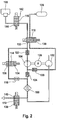
- FIG. 2 shows the switch states in the regeneration phase of the air dryer 100 in OLV mode.
- switching state 132 of the switching valve 110 air flows from the compressed air reservoir 106 first in the first compressor 104, with the dryer valve 114 open in the switching state 136 after passage of a throttle 118, which relaxes the air, in the air dryer 100 and finally with open switching state 140 of the ambient valve 112th delivered to the environment. This also corresponds to the process of venting the closed system.
- the Fig. 3a shows the switching state of the pneumatic control device in a phase of the control operation, wherein in the first switching state 130 of the switching valve 110, the air is displaced exclusively in the direction of the pneumatic actuator system 108 to the compressed air storage 106, bypassing the air dryer 100.
- a check valve 120 connected between the changeover valve 110 and the first compressor 104 prevents the backflow of air from the first compressor 104 to the changeover valve 110.
- Another check valve 124 disposed between the air dryer 100 and the first compressor 104 prevents that air flows into the air dryer 100.
- a first check valve 122 connected between the first compressor 104 and the turn-over valve 110 prevents air from flowing back into the first compressor 104.
- the dryer valve 114 is in the closed switching state 134, so that no air can flow into the air dryer 100.
- the Fig. 3b shows the switching state of the pneumatic control device in a further phase of the control operation, wherein in the second switching state 132 of the switching valve 110, the air is displaced exclusively in the direction of the compressed air reservoir 106 to the pneumatic actuator system 108, bypassing the air dryer 100.
- the check valve 120 which is connected between the switching valve 110 and the first compressor 104, also in this case prevents the return flow of air from the first compressor 104 to the switching valve 110.
- the third check valve 124 which is disposed between the air dryer 100 and the first compressor 104 is here also prevents air from flowing into the air dryer 100.
- the first check valve 122 which is interposed between the first compressor 104 and the turn-over valve 110, prevents air from flowing back into the first compressor 104.
- the dryer valve 114 is in the closed switching state 134, so that no air can flow into the air dryer 100.
- FIG. 5 shows a further embodiment of the switching valve 110 in the form of a combination of two 3/2-way valves 500 and 502 with their switching states 504 and 506 and 508 and 510, which can be used in a circuit of a pneumatic control device.
Landscapes
- Engineering & Computer Science (AREA)
- Mechanical Engineering (AREA)
- General Engineering & Computer Science (AREA)
- Chemical & Material Sciences (AREA)
- Analytical Chemistry (AREA)
- Physics & Mathematics (AREA)
- Fluid Mechanics (AREA)
- Valves And Accessory Devices For Braking Systems (AREA)
- Fluid-Pressure Circuits (AREA)
- Vehicle Body Suspensions (AREA)
Claims (8)
- Montage de sécheur pour un dispositif de régulation pneumatique d'un véhicule, comprenant :- un sécheur d'air (100),- un premier compresseur (104),le premier compresseur (104) étant réalisé pour comprimer l'air de système présent dans le dispositif de régulation pneumatique, le sécheur d'air (100), le premier compresseur (104) et des sous-systèmes du dispositif de régulation pneumatique pouvant être raccordés au premier compresseur (104) étant disposés de telle sorte qu'en mode de fonctionnement d'une alimentation en air fermée, de l'air soit refoulé en contournant le sécheur d'air (100) entre les composants de l'un des sous-systèmes en utilisant le premier compresseur (104) et au moyen d'une soupape de commutation (110, 500, 502) qui est réalisée sous forme de soupape à 4/2 voies (110) ou sous forme d'une combinaison de deux soupapes à 3/2 voies (500, 502), caractérisé en ce que le montage de sécheur comprend en outre un deuxième compresseur (102), le sécheur d'air (100) étant disposé entre le premier et le deuxième compresseur (104, 102), et le deuxième compresseur (102) étant réalisé, en mode de fonctionnement d'une alimentation en air ouverte, de manière à comprimer de l'air nouvellement acheminé, à partir d'un environnement extérieur, à un premier niveau de pression inférieur et à refouler cet air comprimé à travers le sécheur d'air (100) dans le premier compresseur (104) sous forme d'air séché, et le premier compresseur (104) étant réalisé de manière à comprimer l'air séché à un deuxième niveau de pression plus élevé et à le refouler aux sous-systèmes du dispositif de régulation pneumatique raccordés au premier compresseur (104).
- Dispositif selon la revendication 1, dans lequel un premier clapet antiretour (122) disposé au niveau d'un côté de sortie du premier compresseur (104) est réalisé de manière à empêcher un reflux dans le premier compresseur (104) de l'air comprimé au deuxième niveau de pression.
- Dispositif selon la revendication 2, dans lequel un premier sous-système des sous-systèmes comprend une soupape de sécheur (114), la soupape de sécheur (114) étant disposée entre le premier clapet antiretour (122) et le sécheur d'air (100).
- Dispositif selon les revendications 1 à 3, dans lequel le montage de sécheur comprend en outre une soupape d'environnement (112), la soupape d'environnement (112) étant disposée entre le deuxième compresseur (102) et le sécheur d'air (100) et étant réalisée de manière à permettre un trajet d'air commutable entre le sécheur d'air (100), le deuxième compresseur (102) et l'environnement.
- Dispositif selon la revendication 4, dans lequel la soupape d'environnement (112) peut être commutée électriquement ou pneumatiquement.
- Dispositif selon l'une quelconque des revendications 1 à 5, dans lequel un deuxième sous-système des sous-systèmes est prévu pour un fonctionnement en mode de fonctionnement de l'alimentation en air fermée et comprend un système d'actionneur pneumatique (108) avec une soupape d'ouverture montée en amont (116), un accumulateur d'air sous pression (106) et la soupape de commutation (110), la soupape de commutation (110) étant réalisée de manière à adopter un premier (130) et un deuxième (132) état de commutation, un flux d'air, dans le premier état de commutation (130), étant permis exclusivement dans la direction du système d'actionneur pneumatique (108) vers l'accumulateur d'air sous pression (106) en contournant le sécheur d'air (100) et un flux d'air, dans le deuxième état de commutation (132), étant permis exclusivement dans la direction de l'accumulateur d'air sous pression (106) vers le système d'actionneur pneumatique (108) également en contournant le sécheur d'air (100).
- Dispositif selon la revendication 6, comprenant en outre un deuxième (120) et un troisième (124) clapet antiretour, le deuxième clapet antiretour (120) étant disposé entre la soupape de commutation (110) et le premier compresseur (104) et le troisième clapet antiretour (124) étant disposé entre le premier compresseur (104) et le sécheur d'air (100), le troisième clapet antiretour (124) étant disposé de telle sorte qu'un flux d'air entre la soupape de commutation (110) et le premier compresseur (104) soit permis en contournant le troisième clapet antiretour (124).
- Dispositif selon la revendication 7, dans lequel le deuxième (120) et le troisième (124) clapet antiretour sont réalisés de manière à permettre un flux d'air exclusivement dans la direction du premier compresseur (104).
Applications Claiming Priority (3)
| Application Number | Priority Date | Filing Date | Title |
|---|---|---|---|
| DE102011004896 | 2011-03-01 | ||
| DE102011083614A DE102011083614A1 (de) | 2011-03-01 | 2011-09-28 | Trocknerschaltung für eine pneumatische Regelvorrichtung eines Fahrzeugs |
| PCT/EP2012/053085 WO2012116923A1 (fr) | 2011-03-01 | 2012-02-23 | Montage de sécheur d'air pour dispositif de réglage pneumatique d'un véhicule |
Publications (2)
| Publication Number | Publication Date |
|---|---|
| EP2681060A1 EP2681060A1 (fr) | 2014-01-08 |
| EP2681060B1 true EP2681060B1 (fr) | 2016-04-20 |
Family
ID=46671432
Family Applications (1)
| Application Number | Title | Priority Date | Filing Date |
|---|---|---|---|
| EP12705308.0A Active EP2681060B1 (fr) | 2011-03-01 | 2012-02-23 | Montage de sécheur d'air pour dispositif de réglage pneumatique d'un véhicule |
Country Status (5)
| Country | Link |
|---|---|
| US (1) | US9829248B2 (fr) |
| EP (1) | EP2681060B1 (fr) |
| CN (1) | CN103502028B (fr) |
| DE (1) | DE102011083614A1 (fr) |
| WO (1) | WO2012116923A1 (fr) |
Families Citing this family (16)
| Publication number | Priority date | Publication date | Assignee | Title |
|---|---|---|---|---|
| DE102012006382A1 (de) * | 2012-03-30 | 2013-10-02 | Wabco Gmbh | Druckmittelversorgungsanlage, pneumatisches System und Verfahren zum Betreiben einer Druckmittelversorgungsanlage |
| DE102014003927A1 (de) * | 2014-03-19 | 2015-09-24 | Man Truck & Bus Ag | Betriebsverfahren für eine Druckluftaufbereitungseinrichtung für ein Nutzfahrzeug |
| DE102014009419B4 (de) * | 2014-06-25 | 2023-06-07 | Zf Cv Systems Hannover Gmbh | Druckluftversorgungsanlage, pneumatisches System und Verfahren zum Steuern einer Druckluftversorgungssanlage |
| DE102014010956B4 (de) * | 2014-06-25 | 2023-06-15 | Zf Cv Systems Hannover Gmbh | Druckluftversorgungsanlage, pneumatisches System und Verfahren zum Betreiben einer Druckluftversorgungsanlage |
| DE102015010347A1 (de) * | 2015-08-06 | 2017-02-09 | Man Truck & Bus Ag | Betriebsverfahren für eine Druckluftaufbereitungseinrichtung für ein Nutzfahrzeug |
| DE102015219618C5 (de) * | 2015-10-09 | 2025-08-14 | Continental Automotive Technologies GmbH | Integrierte Luftversorgungseinheit mit Lufttrockner und Luftfedersystem, sowie Steuerung einer Luftversorgungseinheit |
| DE102015222230B4 (de) * | 2015-11-11 | 2021-10-28 | Continental Teves Ag & Co. Ohg | Geschlossene Niveauregelanlage mit zwei Verdichtern |
| DE102017004369A1 (de) * | 2017-05-05 | 2018-11-08 | Wabco Gmbh | Verfahren zum Betreiben einer Druckregelanlage mit einem mehrstufigen Kompressor, sowie Druckregelanlage |
| DE102017004360A1 (de) | 2017-05-05 | 2018-11-08 | Wabco Gmbh | Verfahren zum Betreiben einer Druckregelanlage mit einem mehrstufigen Kompressor, sowie Druckregelanlage |
| DE102017004338A1 (de) | 2017-05-05 | 2018-11-08 | Wabco Gmbh | Verfahren zum Betreiben einer Druckregelanlage in einem Fahrzeug sowie Druckregelanlage |
| DE102017004359A1 (de) | 2017-05-05 | 2018-11-08 | Wabco Gmbh | Verfahren zum Betreiben einer Druckregelanlage mit einem mehrstufigen Kompressor, sowie Druckregelanlage |
| DE102017004361A1 (de) | 2017-05-05 | 2018-11-08 | Wabco Gmbh | Verfahren zum Betreiben einer Druckregelanlage mit einem mehrstufigen Kompressor, sowie Druckregelanlage |
| DE102017004414A1 (de) | 2017-05-05 | 2018-11-08 | Wabco Gmbh | Drosselanordnung sowie Druckregelanlage mit einer derartigen Drosselanordnung |
| EP3660335A1 (fr) * | 2018-11-27 | 2020-06-03 | Berlin Heart GmbH | Unité de commutation et système pneumatique |
| CN112387556B (zh) * | 2020-11-16 | 2022-10-25 | 上汽大众汽车有限公司 | 烘房设备的控制方法 |
| DE102024119980A1 (de) * | 2024-07-12 | 2026-01-15 | Zf Cv Systems Europe Bv | Druckluftversorgungssystem, pneumatisches System, Fahrzeug und Betriebsverfahren |
Family Cites Families (20)
| Publication number | Priority date | Publication date | Assignee | Title |
|---|---|---|---|---|
| DE19918157C1 (de) | 1999-04-22 | 2000-10-26 | Continental Ag | Niveauregeleinrichtung für Fahrzeuge mit Luftfedern |
| US6442203B1 (en) | 1999-11-05 | 2002-08-27 | Demografx | System and method for motion compensation and frame rate conversion |
| DE19959556C1 (de) | 1999-12-10 | 2000-12-14 | Continental Ag | Geschlossene Niveauregeleinrichtung für Fahrzeuge |
| DE10016970C1 (de) * | 2000-04-06 | 2001-07-26 | Continental Ag | Niveauregelanlage mit einem Druckluftspeicher und einem Reifenfüllanschluss |
| DE20102436U1 (de) | 2001-02-13 | 2001-06-21 | Arnold Müller GmbH & Co KG, 73230 Kirchheim | Druckluftregeleinrichtung |
| EP1243447B1 (fr) | 2001-03-24 | 2005-12-21 | Continental Aktiengesellschaft | Dispositif fermé de réglage du niveau pour véhicules |
| DE20108696U1 (de) | 2001-05-25 | 2001-08-30 | PNP Luftfedersysteme GmbH, 19089 Crivitz | Mehrstufiger Kolbenverdichter |
| DE10164948A1 (de) | 2001-12-11 | 2007-09-20 | Daimlerchrysler Ag | Verfahren zur Regelung der Luftmenge in einem Niveauregulierungssystem |
| GB0215421D0 (en) * | 2002-07-03 | 2002-08-14 | Wabco Automotive Uk Ltd | Vehicle air supply system |
| DE10240357B4 (de) * | 2002-09-02 | 2016-10-06 | Wabco Gmbh | Luftfederungsanlage für ein Fahrzeug |
| DE10314570A1 (de) | 2003-03-31 | 2004-10-21 | Bf Consulting Gmbh | Dezentrale geschlossene Niveauregeleinrichtung für Kraftfahrzeuge |
| KR100579453B1 (ko) | 2004-07-22 | 2006-05-15 | 현대모비스 주식회사 | 차량의 에어 서스펜션 시스템 |
| KR100599487B1 (ko) * | 2004-09-06 | 2006-07-12 | 현대모비스 주식회사 | 폐루프 차고조절시스템 |
| DE102005028328A1 (de) * | 2005-06-18 | 2006-12-21 | Daimlerchrysler Ag | Pneumatisches Federungssystem |
| US7617031B2 (en) * | 2005-06-23 | 2009-11-10 | Gm Global Technology Operations, Inc. | Series arranged air compressors system |
| AT9131U1 (de) * | 2005-08-31 | 2007-05-15 | Magna Steyr Fahrzeugtechnik Ag | Reifenfüllanlage |
| DE102006043608A1 (de) * | 2006-09-16 | 2008-03-27 | Continental Aktiengesellschaft | Verfahren zur Steuerung und/oder Regelung des Niveaus eines Fahrzeugaufbaus eines Kraftfahrzeuges |
| DE102008023594A1 (de) | 2008-05-14 | 2009-11-19 | Wabco Gmbh | Kompressoreinheit |
| DE102008034240B4 (de) | 2008-07-23 | 2014-12-18 | Wabco Gmbh | Niveauregelanlage für Fahrzeuge und Verfahren zum Betreiben einer Niveauregelanlage |
| DE102009003472A1 (de) * | 2009-02-12 | 2010-08-19 | Continental Aktiengesellschaft | Geschlossene Niveauregelanlage für Fahrzeuge |
-
2011
- 2011-09-28 DE DE102011083614A patent/DE102011083614A1/de not_active Withdrawn
-
2012
- 2012-02-23 WO PCT/EP2012/053085 patent/WO2012116923A1/fr not_active Ceased
- 2012-02-23 US US14/002,194 patent/US9829248B2/en not_active Expired - Fee Related
- 2012-02-23 CN CN201280021265.9A patent/CN103502028B/zh not_active Expired - Fee Related
- 2012-02-23 EP EP12705308.0A patent/EP2681060B1/fr active Active
Also Published As
| Publication number | Publication date |
|---|---|
| CN103502028A (zh) | 2014-01-08 |
| DE102011083614A1 (de) | 2012-09-06 |
| US9829248B2 (en) | 2017-11-28 |
| CN103502028B (zh) | 2016-01-20 |
| EP2681060A1 (fr) | 2014-01-08 |
| US20140059876A1 (en) | 2014-03-06 |
| WO2012116923A1 (fr) | 2012-09-07 |
Similar Documents
| Publication | Publication Date | Title |
|---|---|---|
| EP2681060B1 (fr) | Montage de sécheur d'air pour dispositif de réglage pneumatique d'un véhicule | |
| DE10303399B4 (de) | Verfahren zum Betrieb einer Luftfederungsanlage für ein Fahrzeug | |
| EP2582560B1 (fr) | Dispositif, procédé et système de commande pneumatique et d'alimentation pneumatique | |
| EP2407231B1 (fr) | Dispositif de traitement à l'air comprimé avec deux cartouches de séchage de l'air | |
| EP2129565B1 (fr) | Dispositif d'alimentation en air comprimé conçu pour un véhicule utilitaire, et procédé pour faire fonctionner un dispositif d'alimentation en air comprimé | |
| DE10240357B4 (de) | Luftfederungsanlage für ein Fahrzeug | |
| DE102017010772B4 (de) | Druckluftversorgungsanlage zum Betreiben einer Pneumatikanlage eines Fahrzeugs und Verfahren zum Betrieb einer Druckluftversorgungsanlage | |
| DE102014012646B4 (de) | Druckluftversorgungsanlage, pneumatisches System und Verfahren zum Steuern einer Druckluftversorgungsanlage | |
| EP2396184B1 (fr) | Système fermé régulateur de niveau pour véhicules | |
| DE112018000542B4 (de) | Aufhängungsystem | |
| WO2019115033A1 (fr) | Installation de production d'air comprimé pour faire fonctionner une installation pneumatique, procédé et véhicule | |
| DE112019004801T5 (de) | Luftfederungsvorrichtung | |
| DE112015005084T5 (de) | Luftfederungsvorrichtung | |
| DE112017001662B4 (de) | Luftfedersystem | |
| WO2009138143A1 (fr) | Ensemble de compresseurs | |
| DE112017003753T5 (de) | Luftfederungssystem | |
| EP3724515A1 (fr) | Installation de production d'air comprimé pour faire fonctionner une installation pneumatique, procédé et véhicule | |
| EP2080914B1 (fr) | Dispositif de moyen de pression d'un véhicule | |
| WO2013041434A1 (fr) | Système de réglage de niveau en circuit fermé | |
| DE102024120017A1 (de) | Druckluftversorgungsanlage für ein pneumatisches System eines Fahrzeugs, pneumatisches System mit Druckluftversorgungsanlage und Pneumatikanlage, Fahrzeug und Verfahren zum Betreiben der Druckluftversorgungsanlage und/oder des pneumatischen Systems | |
| DE102023120530A1 (de) | Niveauregelsystem für Fahrzeuge sowie Verfahren zum Betreiben des Niveauregelsystems | |
| WO2023227268A1 (fr) | Dispositif de génération d'air comprimé et son procédé de fonctionnement | |
| DE102024113975A1 (de) | Druckluftversorgungsanlage für ein pneumatisches System eines Fahrzeugs, pneumatisches System mit Druckluftversorgungsanlage und Pneumatikanlage, Fahrzeug mit einem pneumatischen System und Verfahren zum Betreiben einer Druckluftversorgungsanlage oder eines pneumatischen Systems oder von beidem | |
| DE102024113976A1 (de) | Druckluftversorgungsanlage, pneumatisches System, Fahrzeug und Verfahren zum Betreiben eines pneumatischen Systems | |
| DE102024119979A1 (de) | Druckluftversorgungssystem, pneumatisches System, Fahrzeug und Betriebsverfahren |
Legal Events
| Date | Code | Title | Description |
|---|---|---|---|
| PUAI | Public reference made under article 153(3) epc to a published international application that has entered the european phase |
Free format text: ORIGINAL CODE: 0009012 |
|
| 17P | Request for examination filed |
Effective date: 20131001 |
|
| AK | Designated contracting states |
Kind code of ref document: A1 Designated state(s): AL AT BE BG CH CY CZ DE DK EE ES FI FR GB GR HR HU IE IS IT LI LT LU LV MC MK MT NL NO PL PT RO RS SE SI SK SM TR |
|
| DAX | Request for extension of the european patent (deleted) | ||
| 17Q | First examination report despatched |
Effective date: 20150306 |
|
| GRAP | Despatch of communication of intention to grant a patent |
Free format text: ORIGINAL CODE: EPIDOSNIGR1 |
|
| INTG | Intention to grant announced |
Effective date: 20151113 |
|
| GRAS | Grant fee paid |
Free format text: ORIGINAL CODE: EPIDOSNIGR3 |
|
| GRAA | (expected) grant |
Free format text: ORIGINAL CODE: 0009210 |
|
| AK | Designated contracting states |
Kind code of ref document: B1 Designated state(s): AL AT BE BG CH CY CZ DE DK EE ES FI FR GB GR HR HU IE IS IT LI LT LU LV MC MK MT NL NO PL PT RO RS SE SI SK SM TR |
|
| REG | Reference to a national code |
Ref country code: GB Ref legal event code: FG4D Free format text: NOT ENGLISH |
|
| REG | Reference to a national code |
Ref country code: CH Ref legal event code: EP |
|
| REG | Reference to a national code |
Ref country code: AT Ref legal event code: REF Ref document number: 792001 Country of ref document: AT Kind code of ref document: T Effective date: 20160515 |
|
| REG | Reference to a national code |
Ref country code: IE Ref legal event code: FG4D Free format text: LANGUAGE OF EP DOCUMENT: GERMAN |
|
| REG | Reference to a national code |
Ref country code: DE Ref legal event code: R096 Ref document number: 502012006795 Country of ref document: DE |
|
| REG | Reference to a national code |
Ref country code: LT Ref legal event code: MG4D |
|
| REG | Reference to a national code |
Ref country code: NL Ref legal event code: MP Effective date: 20160420 |
|
| PG25 | Lapsed in a contracting state [announced via postgrant information from national office to epo] |
Ref country code: FI Free format text: LAPSE BECAUSE OF FAILURE TO SUBMIT A TRANSLATION OF THE DESCRIPTION OR TO PAY THE FEE WITHIN THE PRESCRIBED TIME-LIMIT Effective date: 20160420 Ref country code: NL Free format text: LAPSE BECAUSE OF FAILURE TO SUBMIT A TRANSLATION OF THE DESCRIPTION OR TO PAY THE FEE WITHIN THE PRESCRIBED TIME-LIMIT Effective date: 20160420 Ref country code: PL Free format text: LAPSE BECAUSE OF FAILURE TO SUBMIT A TRANSLATION OF THE DESCRIPTION OR TO PAY THE FEE WITHIN THE PRESCRIBED TIME-LIMIT Effective date: 20160420 Ref country code: LT Free format text: LAPSE BECAUSE OF FAILURE TO SUBMIT A TRANSLATION OF THE DESCRIPTION OR TO PAY THE FEE WITHIN THE PRESCRIBED TIME-LIMIT Effective date: 20160420 Ref country code: NO Free format text: LAPSE BECAUSE OF FAILURE TO SUBMIT A TRANSLATION OF THE DESCRIPTION OR TO PAY THE FEE WITHIN THE PRESCRIBED TIME-LIMIT Effective date: 20160720 |
|
| PG25 | Lapsed in a contracting state [announced via postgrant information from national office to epo] |
Ref country code: ES Free format text: LAPSE BECAUSE OF FAILURE TO SUBMIT A TRANSLATION OF THE DESCRIPTION OR TO PAY THE FEE WITHIN THE PRESCRIBED TIME-LIMIT Effective date: 20160420 Ref country code: HR Free format text: LAPSE BECAUSE OF FAILURE TO SUBMIT A TRANSLATION OF THE DESCRIPTION OR TO PAY THE FEE WITHIN THE PRESCRIBED TIME-LIMIT Effective date: 20160420 Ref country code: GR Free format text: LAPSE BECAUSE OF FAILURE TO SUBMIT A TRANSLATION OF THE DESCRIPTION OR TO PAY THE FEE WITHIN THE PRESCRIBED TIME-LIMIT Effective date: 20160721 Ref country code: LV Free format text: LAPSE BECAUSE OF FAILURE TO SUBMIT A TRANSLATION OF THE DESCRIPTION OR TO PAY THE FEE WITHIN THE PRESCRIBED TIME-LIMIT Effective date: 20160420 Ref country code: PT Free format text: LAPSE BECAUSE OF FAILURE TO SUBMIT A TRANSLATION OF THE DESCRIPTION OR TO PAY THE FEE WITHIN THE PRESCRIBED TIME-LIMIT Effective date: 20160822 Ref country code: SE Free format text: LAPSE BECAUSE OF FAILURE TO SUBMIT A TRANSLATION OF THE DESCRIPTION OR TO PAY THE FEE WITHIN THE PRESCRIBED TIME-LIMIT Effective date: 20160420 Ref country code: RS Free format text: LAPSE BECAUSE OF FAILURE TO SUBMIT A TRANSLATION OF THE DESCRIPTION OR TO PAY THE FEE WITHIN THE PRESCRIBED TIME-LIMIT Effective date: 20160420 |
|
| PG25 | Lapsed in a contracting state [announced via postgrant information from national office to epo] |
Ref country code: IT Free format text: LAPSE BECAUSE OF FAILURE TO SUBMIT A TRANSLATION OF THE DESCRIPTION OR TO PAY THE FEE WITHIN THE PRESCRIBED TIME-LIMIT Effective date: 20160420 |
|
| REG | Reference to a national code |
Ref country code: DE Ref legal event code: R097 Ref document number: 502012006795 Country of ref document: DE |
|
| PG25 | Lapsed in a contracting state [announced via postgrant information from national office to epo] |
Ref country code: DK Free format text: LAPSE BECAUSE OF FAILURE TO SUBMIT A TRANSLATION OF THE DESCRIPTION OR TO PAY THE FEE WITHIN THE PRESCRIBED TIME-LIMIT Effective date: 20160420 Ref country code: RO Free format text: LAPSE BECAUSE OF FAILURE TO SUBMIT A TRANSLATION OF THE DESCRIPTION OR TO PAY THE FEE WITHIN THE PRESCRIBED TIME-LIMIT Effective date: 20160420 Ref country code: SK Free format text: LAPSE BECAUSE OF FAILURE TO SUBMIT A TRANSLATION OF THE DESCRIPTION OR TO PAY THE FEE WITHIN THE PRESCRIBED TIME-LIMIT Effective date: 20160420 Ref country code: CZ Free format text: LAPSE BECAUSE OF FAILURE TO SUBMIT A TRANSLATION OF THE DESCRIPTION OR TO PAY THE FEE WITHIN THE PRESCRIBED TIME-LIMIT Effective date: 20160420 Ref country code: EE Free format text: LAPSE BECAUSE OF FAILURE TO SUBMIT A TRANSLATION OF THE DESCRIPTION OR TO PAY THE FEE WITHIN THE PRESCRIBED TIME-LIMIT Effective date: 20160420 |
|
| REG | Reference to a national code |
Ref country code: FR Ref legal event code: PLFP Year of fee payment: 6 |
|
| PLBE | No opposition filed within time limit |
Free format text: ORIGINAL CODE: 0009261 |
|
| STAA | Information on the status of an ep patent application or granted ep patent |
Free format text: STATUS: NO OPPOSITION FILED WITHIN TIME LIMIT |
|
| PG25 | Lapsed in a contracting state [announced via postgrant information from national office to epo] |
Ref country code: SM Free format text: LAPSE BECAUSE OF FAILURE TO SUBMIT A TRANSLATION OF THE DESCRIPTION OR TO PAY THE FEE WITHIN THE PRESCRIBED TIME-LIMIT Effective date: 20160420 |
|
| 26N | No opposition filed |
Effective date: 20170123 |
|
| PG25 | Lapsed in a contracting state [announced via postgrant information from national office to epo] |
Ref country code: BE Free format text: LAPSE BECAUSE OF NON-PAYMENT OF DUE FEES Effective date: 20170228 Ref country code: SI Free format text: LAPSE BECAUSE OF FAILURE TO SUBMIT A TRANSLATION OF THE DESCRIPTION OR TO PAY THE FEE WITHIN THE PRESCRIBED TIME-LIMIT Effective date: 20160420 |
|
| PG25 | Lapsed in a contracting state [announced via postgrant information from national office to epo] |
Ref country code: MC Free format text: LAPSE BECAUSE OF FAILURE TO SUBMIT A TRANSLATION OF THE DESCRIPTION OR TO PAY THE FEE WITHIN THE PRESCRIBED TIME-LIMIT Effective date: 20160420 |
|
| REG | Reference to a national code |
Ref country code: CH Ref legal event code: PL |
|
| GBPC | Gb: european patent ceased through non-payment of renewal fee |
Effective date: 20170223 |
|
| PG25 | Lapsed in a contracting state [announced via postgrant information from national office to epo] |
Ref country code: CH Free format text: LAPSE BECAUSE OF NON-PAYMENT OF DUE FEES Effective date: 20170228 Ref country code: LI Free format text: LAPSE BECAUSE OF NON-PAYMENT OF DUE FEES Effective date: 20170228 |
|
| REG | Reference to a national code |
Ref country code: IE Ref legal event code: MM4A |
|
| PG25 | Lapsed in a contracting state [announced via postgrant information from national office to epo] |
Ref country code: LU Free format text: LAPSE BECAUSE OF NON-PAYMENT OF DUE FEES Effective date: 20170223 |
|
| REG | Reference to a national code |
Ref country code: BE Ref legal event code: MM Effective date: 20170228 |
|
| REG | Reference to a national code |
Ref country code: FR Ref legal event code: PLFP Year of fee payment: 7 |
|
| PG25 | Lapsed in a contracting state [announced via postgrant information from national office to epo] |
Ref country code: IE Free format text: LAPSE BECAUSE OF NON-PAYMENT OF DUE FEES Effective date: 20170223 Ref country code: GB Free format text: LAPSE BECAUSE OF NON-PAYMENT OF DUE FEES Effective date: 20170223 |
|
| REG | Reference to a national code |
Ref country code: AT Ref legal event code: MM01 Ref document number: 792001 Country of ref document: AT Kind code of ref document: T Effective date: 20170223 |
|
| PG25 | Lapsed in a contracting state [announced via postgrant information from national office to epo] |
Ref country code: AT Free format text: LAPSE BECAUSE OF NON-PAYMENT OF DUE FEES Effective date: 20170223 |
|
| PG25 | Lapsed in a contracting state [announced via postgrant information from national office to epo] |
Ref country code: MT Free format text: LAPSE BECAUSE OF FAILURE TO SUBMIT A TRANSLATION OF THE DESCRIPTION OR TO PAY THE FEE WITHIN THE PRESCRIBED TIME-LIMIT Effective date: 20160420 |
|
| PG25 | Lapsed in a contracting state [announced via postgrant information from national office to epo] |
Ref country code: AL Free format text: LAPSE BECAUSE OF FAILURE TO SUBMIT A TRANSLATION OF THE DESCRIPTION OR TO PAY THE FEE WITHIN THE PRESCRIBED TIME-LIMIT Effective date: 20160420 |
|
| PG25 | Lapsed in a contracting state [announced via postgrant information from national office to epo] |
Ref country code: HU Free format text: LAPSE BECAUSE OF FAILURE TO SUBMIT A TRANSLATION OF THE DESCRIPTION OR TO PAY THE FEE WITHIN THE PRESCRIBED TIME-LIMIT; INVALID AB INITIO Effective date: 20120223 |
|
| PG25 | Lapsed in a contracting state [announced via postgrant information from national office to epo] |
Ref country code: BG Free format text: LAPSE BECAUSE OF FAILURE TO SUBMIT A TRANSLATION OF THE DESCRIPTION OR TO PAY THE FEE WITHIN THE PRESCRIBED TIME-LIMIT Effective date: 20160420 |
|
| PG25 | Lapsed in a contracting state [announced via postgrant information from national office to epo] |
Ref country code: CY Free format text: LAPSE BECAUSE OF NON-PAYMENT OF DUE FEES Effective date: 20160420 |
|
| PG25 | Lapsed in a contracting state [announced via postgrant information from national office to epo] |
Ref country code: MK Free format text: LAPSE BECAUSE OF FAILURE TO SUBMIT A TRANSLATION OF THE DESCRIPTION OR TO PAY THE FEE WITHIN THE PRESCRIBED TIME-LIMIT Effective date: 20160420 |
|
| PG25 | Lapsed in a contracting state [announced via postgrant information from national office to epo] |
Ref country code: TR Free format text: LAPSE BECAUSE OF FAILURE TO SUBMIT A TRANSLATION OF THE DESCRIPTION OR TO PAY THE FEE WITHIN THE PRESCRIBED TIME-LIMIT Effective date: 20160420 |
|
| PG25 | Lapsed in a contracting state [announced via postgrant information from national office to epo] |
Ref country code: IS Free format text: LAPSE BECAUSE OF FAILURE TO SUBMIT A TRANSLATION OF THE DESCRIPTION OR TO PAY THE FEE WITHIN THE PRESCRIBED TIME-LIMIT Effective date: 20160820 |
|
| PGFP | Annual fee paid to national office [announced via postgrant information from national office to epo] |
Ref country code: FR Payment date: 20210225 Year of fee payment: 10 |
|
| REG | Reference to a national code |
Ref country code: DE Ref legal event code: R081 Ref document number: 502012006795 Country of ref document: DE Owner name: CONTINENTAL AUTOMOTIVE TECHNOLOGIES GMBH, DE Free format text: FORMER OWNER: CONTINENTAL TEVES AG & CO. OHG, 60488 FRANKFURT, DE Ref country code: DE Ref legal event code: R081 Ref document number: 502012006795 Country of ref document: DE Owner name: AUMOVIO GERMANY GMBH, DE Free format text: FORMER OWNER: CONTINENTAL TEVES AG & CO. OHG, 60488 FRANKFURT, DE |
|
| PG25 | Lapsed in a contracting state [announced via postgrant information from national office to epo] |
Ref country code: FR Free format text: LAPSE BECAUSE OF NON-PAYMENT OF DUE FEES Effective date: 20220228 |
|
| REG | Reference to a national code |
Ref country code: DE Ref legal event code: R081 Ref document number: 502012006795 Country of ref document: DE Owner name: CONTINENTAL AUTOMOTIVE TECHNOLOGIES GMBH, DE Free format text: FORMER OWNER: CONTINENTAL AUTOMOTIVE TECHNOLOGIES GMBH, 30165 HANNOVER, DE Ref country code: DE Ref legal event code: R081 Ref document number: 502012006795 Country of ref document: DE Owner name: AUMOVIO GERMANY GMBH, DE Free format text: FORMER OWNER: CONTINENTAL AUTOMOTIVE TECHNOLOGIES GMBH, 30165 HANNOVER, DE |
|
| PGFP | Annual fee paid to national office [announced via postgrant information from national office to epo] |
Ref country code: DE Payment date: 20250228 Year of fee payment: 14 |
|
| REG | Reference to a national code |
Ref country code: DE Ref legal event code: R081 Ref document number: 502012006795 Country of ref document: DE Owner name: AUMOVIO GERMANY GMBH, DE Free format text: FORMER OWNER: CONTINENTAL AUTOMOTIVE TECHNOLOGIES GMBH, 30175 HANNOVER, DE |