EP2681136B1 - Waste storage device - Google Patents
Waste storage device Download PDFInfo
- Publication number
- EP2681136B1 EP2681136B1 EP12712970.8A EP12712970A EP2681136B1 EP 2681136 B1 EP2681136 B1 EP 2681136B1 EP 12712970 A EP12712970 A EP 12712970A EP 2681136 B1 EP2681136 B1 EP 2681136B1
- Authority
- EP
- European Patent Office
- Prior art keywords
- dispenser
- waste storage
- storage device
- lid
- powder
- Prior art date
- Legal status (The legal status is an assumption and is not a legal conclusion. Google has not performed a legal analysis and makes no representation as to the accuracy of the status listed.)
- Active
Links
Images







Classifications
-
- B—PERFORMING OPERATIONS; TRANSPORTING
- B65—CONVEYING; PACKING; STORING; HANDLING THIN OR FILAMENTARY MATERIAL
- B65F—GATHERING OR REMOVAL OF DOMESTIC OR LIKE REFUSE
- B65F1/00—Refuse receptacles; Accessories therefor
- B65F1/0006—Flexible refuse receptables, e.g. bags, sacks
- B65F1/002—Flexible refuse receptables, e.g. bags, sacks with means for opening or closing of the receptacle
-
- B—PERFORMING OPERATIONS; TRANSPORTING
- B65—CONVEYING; PACKING; STORING; HANDLING THIN OR FILAMENTARY MATERIAL
- B65D—CONTAINERS FOR STORAGE OR TRANSPORT OF ARTICLES OR MATERIALS, e.g. BAGS, BARRELS, BOTTLES, BOXES, CANS, CARTONS, CRATES, DRUMS, JARS, TANKS, HOPPERS, FORWARDING CONTAINERS; ACCESSORIES, CLOSURES, OR FITTINGS THEREFOR; PACKAGING ELEMENTS; PACKAGES
- B65D33/00—Details of, or accessories for, sacks or bags
- B65D33/16—End- or aperture-closing arrangements or devices
-
- B—PERFORMING OPERATIONS; TRANSPORTING
- B65—CONVEYING; PACKING; STORING; HANDLING THIN OR FILAMENTARY MATERIAL
- B65F—GATHERING OR REMOVAL OF DOMESTIC OR LIKE REFUSE
- B65F1/00—Refuse receptacles; Accessories therefor
- B65F1/04—Refuse receptacles; Accessories therefor with removable inserts
- B65F1/06—Refuse receptacles; Accessories therefor with removable inserts with flexible inserts, e.g. bags or sacks
- B65F1/062—Refuse receptacles; Accessories therefor with removable inserts with flexible inserts, e.g. bags or sacks having means for storing or dispensing spare bags
-
- B—PERFORMING OPERATIONS; TRANSPORTING
- B65—CONVEYING; PACKING; STORING; HANDLING THIN OR FILAMENTARY MATERIAL
- B65F—GATHERING OR REMOVAL OF DOMESTIC OR LIKE REFUSE
- B65F1/00—Refuse receptacles; Accessories therefor
- B65F1/14—Other constructional features; Accessories
- B65F1/16—Lids or covers
- B65F1/1615—Lids or covers with means for locking, fastening or permanently closing thereof
-
- B—PERFORMING OPERATIONS; TRANSPORTING
- B65—CONVEYING; PACKING; STORING; HANDLING THIN OR FILAMENTARY MATERIAL
- B65F—GATHERING OR REMOVAL OF DOMESTIC OR LIKE REFUSE
- B65F1/00—Refuse receptacles; Accessories therefor
- B65F1/14—Other constructional features; Accessories
- B65F1/16—Lids or covers
- B65F1/1623—Lids or covers with means for assisting the opening or closing thereof, e.g. springs
- B65F1/163—Pedal-operated lids
-
- B—PERFORMING OPERATIONS; TRANSPORTING
- B65—CONVEYING; PACKING; STORING; HANDLING THIN OR FILAMENTARY MATERIAL
- B65F—GATHERING OR REMOVAL OF DOMESTIC OR LIKE REFUSE
- B65F7/00—Cleaning or disinfecting devices combined with refuse receptacles or refuse vehicles
-
- B—PERFORMING OPERATIONS; TRANSPORTING
- B65—CONVEYING; PACKING; STORING; HANDLING THIN OR FILAMENTARY MATERIAL
- B65F—GATHERING OR REMOVAL OF DOMESTIC OR LIKE REFUSE
- B65F7/00—Cleaning or disinfecting devices combined with refuse receptacles or refuse vehicles
- B65F7/005—Devices, mounted on refuse collecting vehicles, for cleaning or disinfecting refuse receptacles
-
- B—PERFORMING OPERATIONS; TRANSPORTING
- B65—CONVEYING; PACKING; STORING; HANDLING THIN OR FILAMENTARY MATERIAL
- B65F—GATHERING OR REMOVAL OF DOMESTIC OR LIKE REFUSE
- B65F2210/00—Equipment of refuse receptacles
- B65F2210/167—Sealing means
Definitions
- the invention relates to a waste storage device and cassette and more particularly to a waste storage device according to the preamble of claim 1.
- a variety of products are commercially available for depositing and temporarily storing waste, for example used infant nappies or diapers.
- Many of these products comprise a waste storage device or tub, including a waste storage compartment which can house deposited waste packages, working in conjunction with a waste cassette or cartridge which comprises a plastic bag or tubing.
- the plastic bag or tubing is used to hold or wrap waste packages inside the waste storage device, to provide a hygienic barrier and to enable the user to empty the waste packages from the waste storage device.
- waste storage devices Primary concerns for users of waste storage devices are hygiene and ease of use. Particularly when the waste to be stored is a used infant nappy or diaper, consumers, i.e. parents or carers of the infants, place a high value on ensuring that the waste storage device can be kept clean and odour free. They also want to be confident that the waste cannot escape either whilst it is being stored in the waste storage device or whilst it is being emptied therefrom. Busy parents or carers also need a waste storage system to be straight forward to use and to function reliably. Increasingly, environmental factors are also of concern to consumers, such that it is desirable for a waste storage system to use non-biodegradable materials such as plastic minimally and as efficiently as possible.
- US 7878359 discloses a trash can with a deodorising mechanism comprising a body having an opening formed at the top of the body, a lid pivotally coupled to the top of the body for performing an opening or closing movement, and a deodorising mechanism installed on the body and including a bottle and a nozzle.
- GB 453291 discloses a disinfectant container for use with bin-lids comprising an outlet at its base normally closed by a conical spreader and stem normally thrust upwardly by a spring and extending above the lid, the arrangement being such that depression of the stem opens the outlet.
- US 2147139 discloses a container with a cover, and means for deodorising the container to prevent the attraction of flies and insects and to eliminate unpleasant fumes or odours.
- the apparatus includes a cup-shaped casing having perforated side walls which may serve as a support or receptacle for a body or cake of deodorising material.
- US 3 214 065 A discloses a waste storage device according to the preamble of claim 1 for powdered disinfecting and/or deodorising material having a neck portion provided with dispensing means whereby powder from the container is allowed to escape and become sprinkled when the container is in inverted attitude and is subjected to mechanical disturbance.
- a waste storage device comprising a waste storage compartment for storing waste and a lid.
- the device further comprises a dispenser for dispensing an agent inside the waste storage device and an actuator arranged to activate the dispenser.
- the actuator may also actuate opening and/or closing of the lid. Or the actuator may be actuatable when the lid is closed.
- the agent may have anti-bacterial and/or anti-odour properties.
- the agent is in powder form.
- One advantage provided by the invention is that the user can depress or deflect the actuator on the outside of the lid of the waste storage device in order to cause movement of the air in the dispenser cavity, thereby agitating the powdered agent therein in order to distribute that agent in a controlled manner within the waste storage device.
- a waste storage device comprising a waste storage compartment for storing waste, a lid and a dispenser attachable to said lid.
- the dispenser comprises a reservoir of liquid, and the device further comprises a wick for dispensing said liquid inside a waste storage device.
- the liquid may include a fragrance. It may be an oil, such as an essential oil.
- a waste storage device comprising a waste storage compartment for storing waste, a lid and a dispenser attachable to said lid for dispensing an agent inside the waste storage device.
- the dispenser When the dispenser is attached to the lid, at least a portion of the dispenser is moveable with respect to the lid.
- the dispenser may attach to the lid via a screw thread which allows for relative movement between the dispenser and the lid in a direction substantially perpendicular to the plane of the lid.
- a waste cartridge comprising a relatively rigid upper portion and a relatively flexible lower portion, wherein said relatively flexible lower portion is arranged for storing waste items and wherein said relatively rigid upper portion is arranged to be folded about an axis in a direction substantially towards the lower portion of the waste cartridge.
- the upper portion may comprise a ring or other formation via which the cartridge can be supported or suspended in a waste storage device.
- the lower portion may comprise a bag or length or tubing for storing waste items.
- the upper portion may comprise cooperating formations for creating an air tight seal at the top of the bag or flexible tubing when the upper portion is folded.
- the waste storage device includes dispensing means for dispensing an antibacterial and/or anti-odour agent inside a waste storage device.
- the antibacterial and/or anti-odour agent is in powder form.
- An activation means is provided for activating the dispenser in order to distribute the antibacterial and/or anti-odour agent within a waste storage device.
- the activation may be linked to actuation of the lid of the waste storage device, including actuation using a foot pedal, or activation of the dispenser may be independent of operation of the lid and other components of the waste storage device.
- the dispenser may be a spray-type dispenser such as an aerosol or may comprise a reservoir of fluid and a wick for distributing the fluid.
- the dispensing and actuation means are shaped, sized and arranged so as to distribute antibacterial and/or anti-odour agent in a desired area within a waste storage device.
- the agent may be distributed onto a plastic bag or length of flexible tubing extending from a waste storage cassette or cartridge inside the waste storage device, into which a user will place a waste object when the lid of the device is open. It is possible for the dispenser to be moveable within the device to vary the area onto which the agent is distributed. It is also possible to dose the amount of agent distributed within the device at any given time.
- the waste cartridge comprises a foldable cartridge including a bag for storing waste packages and an upper ring for sealing the top of the bag.
- the upper ring may also be used to fix the waste cartridge in a waste storage device for use, for example by supporting the ring on or suspending the ring from a formation within the waste storage device.
- the ring at the top of the bag is folded downwards and the two sides of the ring are pressed, clipped or otherwise sealed together in order to form an airtight waste sack for removal from a waste storage device.
- the waste storage device and waste cartridge may be used in conjunction with one another or with other waste storage products. Both separately and together, they provide a waste storage device system that is straightforward and cost-effective for the user and which improves hygiene and odour prevention as compared to known waste storage systems.
- FIG. 1 shows an example of a known waste storage device. This device is described in more detail in International patent application number PCT/GB2007/004410 , in the name of Sangenic International Limited, but is shown herein by way of example only.
- the waste storage device 100 comprises a bottom section 102 which includes a waste storage compartment therein, a top section 104 which is removably attachable to the bottom section 102, and a lid 106 for opening and closing the waste storage device 100.
- many different types of waste storage device are known, almost all of which comprise the basic component parts as described herein with respect to figure 1 .
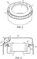
- FIG. 2 shows an example of a waste storage cassette that can be used in conjunction with a waste storage device.
- the waste storage cassette shown in figure 2 is described in more detail in international patent application number PCT/GB2008/002360 , in the name of Sangenic International Limited, but is shown herein by way of example only.
- the waste storage cassette 108 comprises inner and outer walls defining a cavity 110 therebetween.
- the cavity 110 can be used to house plastic bags or tubing for holding and/or wrapping waste packages.
- the cassette 108 can be placed in the top section 104 of a waste storage device 100.
- the cassette 108 in figure 2 has a flange 114 around its outer wall, by which it can be supported on or suspended in a waste storage device 100.
- the inner wall of the cassette 108 in figure 2 defines a central core 112.
- a waste package can be placed in a bag or length of tubing supplied from the cavity 110 of the waste storage cassette 108 and fed through the central core 112 of the cassette 108 through to the waste storage compartment of the waste storage device 100, below the waste storage cassette 108.
- a waste storage cassette or cartridge which supplies flexible tubing for wrapping waste may be rotatable inside a waste storage device, wherein rotation occurs between successive deposits of waste packages so that a twist is formed in the flexible tubing between successive waste packages.
- This "twist and seal" approach enables discrete waste packages to be wrapped and provides a barrier between the wrapped packages and the central core 112 of the cassette, through which odours or waste material might otherwise escape during use of the waste storage device.
- Other approaches include providing one or more antechambers between the point at which a waste package is deposited in a waste storage device and the waste storage compartment therebelow.
- an airlock can be provided between a user depositing a new waste package and the existing waste packages being stored in the waste storage device.
- means may be provided in a waste storage device for masking or neutralising odours created by the waste packages deposited therein.
- means may be provided for distributing anti-bacterial agents in a waste storage device to provide improved hygiene for the user.
- Spray Dispenser for Dispensing Anti-bacterial and/or Anti-odour Agent
- FIG 3 shows a waste storage system, of an aspect not forming part of the claimed invention.
- the waste storage system comprises a waste storage device 200, shown in figure 3 with a waste storage cassette 202 housed therein.
- the device 200 and cassette 202 can be manufactured and sold independently of one another.
- the cassette 202 is suspended from a shelf 204 provided in an upper portion of the waste storage device 200.
- a shelf 204 may be fixed within the waste storage device or it may be movable therein, for example it may be comprised in a waste cassette rotator which can rotate about a central axis inside the device 200. Rather than being suspended, the cassette could be supported on a formation inside the waste storage device 200.
- the waste storage device 200 as shown in figure 3 further comprises a lid 206.
- the lid 206 can be opened and closed to provide user access to the inside of the waste storage device 200.
- the lid 206 is pivotally attached to an upper portion of the waste storage device 200, however any suitable attachment between the lid 206 and waste storage device 200 may be used.
- Housed inside the lid 206, in the upper left hand corner of the cross-section shown in figure 3 is a dispenser 208.
- the dispenser 208 comprises a storage portion and a spray mechanism.
- the dispenser 208 is a canister which has an actuator at its top end which can be depressed to activate the spray mechanism.
- the storage portion can contain liquid or gas, for example compressed gas, which can act as an anti-bacterial agent and/or an anti-odour agent. If anti-odour agent is used it can comprise fragrance and/or deodorising chemicals. By way of example, the anti-bacterial agents could be based on silver ion technology.
- the dispenser 208 is activated by opening the lid 206.
- the dispenser 208 can be housed between first 210 and second 212 projections which project from an inner surface of the lid 206.
- the first projection 210 lies substantially flush with an upper surface of the dispenser 208 in situ and the second projection lies substantially flush with a lower surface of the dispenser 208 so that the dispenser is effectively wedged therebetween.
- the projections 210, 212 could comprise engagement means for fitting around or interlocking with the dispenser 208 in order to hold it in place.
- the location of the second projection 212 is selected so that a force exerted by the user on an outer surface of the lid 206 of the waste storage device 200 in order to open the lid 206 will cause displacement of the second projection 212.
- the lid 206 includes a thin portion 214 which terminates in a hook 216.
- the hook 216 interacts with a lip 218 on the waste storage device 200 in order to provide engagement between the lid 206 and the waste storage device 200 and thereby close the lid 206. Due to its reduced thickness as compared to the rest of the lid 206, the thin portion 214 is quite flexible.
- the user can press the thin portion 214 in order to flex it and disengage the hook 216 from the lip 218 of the waste storage device 200, thereby opening the lid 206.
- Such a movement of the thin portion 214 as shown in figure 3 will cause flexion of the second projection 212 inside the lid 206 but will not cause flexion of the first projection 210.
- a force is exerted on the ends of the dispenser, depressing the actuator at the top end and thereby activating the dispenser 208 to spray out some of the agent stored therein.
- the agent can be anti-bacterial, and/or anti-odour, such that when the user opens the lid 206 to place a waste package inside the waste storage device 200, he or she will be presented with a clean and odour free surface inside the waste storage device 200.
- the dispenser 208 as shown in figure 3 can be angled so as to distribute agent onto a selected surface inside the waste storage device 200. For example it could spray anti-bacterial or anti-odour agent on the flexible tubing being dispensed from the waste storage cassette 202, into which the user will place a waste object. Furthermore, the dispenser 208 can be arranged so that a limited portion of the agent will be sprayed out upon user actuation of the lid 206.
- Various types of spray mechanisms, canisters and aerosols will be well known to the skilled reader, many of which can provide controlled portions, such that they will not be described in detail herein.
- Figure 4 shows an alternative device including a dispenser 308 of an aspect not forming part of the claimed invention, housed inside the lid 306 of a waste storage device 300.
- a substantially L-shaped actuator 310 instead of an end of the lid 306 having a depressible thin portion, there is provided a substantially L-shaped actuator 310.
- a first branch of the L-shaped actuator 310 comprises a push button at one end, external to the lid 306, for a user to actuate in order to open the lid 306.
- the first branch extends through the lid 306 and in the device shown on figure 4 terminates substantially flush with a bottom surface of the dispenser 308 housed therein.
- the second branch of the actuator 310 extends downwards substantially perpendicular to the first branch and has a hook 314 on its distal end for inter-engaging with the waste storage device 300 in order to close the lid 306.
- displacement of the L-shaped actuator 310 causes displacement of the dispenser 308, which depresses the spray mechanism and therefore releases a spray of anti-bacterial and/or anti-odour agent from the dispenser 308.
- the components shown therein can be sized appropriately so that the dispenser 308 fits comfortably within the lid 306 without interfering with any other component parts of the waste storage device 300 or with a waste storage cassette or cartridge housed therein. Furthermore the size and configuration of the components can be selected so that a desired amount of spray can be distributed to selected areas inside the waste storage device 300 in order to present a clean and odour free environment to the user.
- FIGS. 3 and 4 show two particular devices wherein user actuation to open the lid of a waste storage device activates a dispenser housed therein, other variations may be used without departing from this principle of operation.
- the lid may be opened by a different mechanism such as another type of deformable or spring loaded actuator.
- the lid need not comprise a hook for engaging with the waste storage device but may engage with the waste storage device via any other suitable locking or inter-engagement means.
- figures 3 and 4 show a dispenser which has a depressible actuator or portion at its upper end, other types of dispenser may equally be used.
- the dispenser may include a hinge mechanism whereby a first portion of the dispenser is fixed relative to an inner surface of the lid or waste storage device and a second portion of the dispenser, hingedly attached to the first portion, is arranged to be deformed when the user presses an actuator to open the lid, whereby deformation of the second portion of the dispenser causes it to hingedly move towards the first portion and thereby release a spray of agent inside the waste storage device.
- the waste storage device may comprise a foot pedal for opening the lid.
- a suitable lever or other mechanism for opening the lid of a waste storage device upon depression of a foot pedal will be known to the skilled reader and therefore will not be described in detail herein.
- FIG 5 an example of a waste storage device having a foot pedal operated lid can be seen in figure 5 , which is an aspect not forming part of the claimed invention,.
- the lid 506 is connected to the foot pedal 504 via at least one substantially vertical connector 502 extending downwardly from the lid 506 and at least one substantially horizontal connector 508 hingedly attached to the substantially vertical connector 502 and having the foot pedal 504 arranged at its distal end.
- the waste storage device 500 of figure 5 is shown with a waste storage cassette 510 housed therein.
- a dispenser for dispensing anti-bacterial and/or anti-odour agent may be incorporated into a foot pedal operated waste storage device such as the one shown in figure 5 in a number of ways.
- a dispenser 608 for dispensing anti-bacterial and/or anti-odour agent is provided in a foot pedal operated waste storage device such as the one shown in figure 5 , located adjacent to and inward of the substantially vertical connector 602 therein.
- the dispenser 608 shown in figure 6 may be a canister or another type of dispenser which has a depressible actuator or portion at the top of the dispenser 608.
- the substantially vertical connector 602 comprises a protrusion 600 which projects from a side of the connector 602 towards the dispenser 608.
- the substantially vertical connector 602 in figure 6 is shown in a raised position which occurs when the foot pedal has been operated and the lid is open.
- the protrusion 600 is positioned vertically above the top of the dispenser 608 when the lid is in the open position.
- the lid closes the substantially vertical connector 602 will move downwards and therefore the protrusion 600 will also move downwards to meet the dispenser 608 and to exert pressure thereon.
- Such pressure of the protrusion 600 on the dispenser 608 activates the dispenser 608 to release a spray of agent inside the waste storage device, for example onto flexible tubing dispensed from the waste storage cassette 510 housed therein.
- Closure of the lid may happen automatically upon release of the foot pedal or may be controlled by the user such that the user can exert sufficient downward force to ensure that the protrusion 600 presses down on the dispenser 608 in order to release a spray of agent.
- Figure 7 shows a variation on the arrangement shown in figure 6 wherein a hinged dispenser 708, of an aspect not forming part of the claimed invention, is provided between the substantially vertical connector 702 and the waste storage cassette 510 in a foot pedal operated waste storage device.
- the dispenser 708 can be held in place by any suitable means so that a first portion 710 of the dispenser 708 remains stationary during actuation of the lid whilst a second portion 720 of the dispenser, hingedly attached to the first portion 710, can be moved during actuation of the lid.
- a protrusion 600 is provided on the substantially vertical connector 702, protruding towards the dispenser 708 such that during closure of the lid the protrusion 600 will exert pressure on the dispenser 708, causing movement of the second portion 720 towards the first portion 710 of the dispenser, thereby releasing a spray of agent therefrom.
- the dispenser and protrusion can be arranged so that the protrusion only causes the dispenser to spray during downward movement of the substantially vertical connector as described above or they can be arranged so that the protrusion causes the dispenser to spray both on upward and downward movement of the substantially vertical connector.
- the system enables bacteria and/or odours to be suppressed just after a waste package has been deposited in the waste storage device, so that the bacteria and/or odour does not linger or spread between consecutive uses of the device.
- a fresh spray will occur as the user opens the lid of the device, therefore ensuring that the device is clean and fresh for the next use. This can be useful when there are relatively long delays between successive uses of a waste storage device.
- FIG. 8 An alternative means for actuation of a dispenser 808 in a foot pedal operated waste storage device of an aspect not forming part of the claimed invention, is shown in figure 8 .
- a profiled projection 800 is provided on the substantially vertical connector 802.
- the profiled projection 800 protrudes from the connector 802, towards the dispenser 808, at its lower end and is profiled so as to slope inwardly and upwardly from that lower end back towards the connector 802.
- the operation of the protrusion 808 is controlled since the risk of it actuating the dispenser 808 whilst the substantially vertical connector 802 is moving upwards during opening of the lid is reduced.
- the profiled projection 800 will instead only depress the dispenser 808 during downward movement of the connector 802 as the lid is being closed.
- the device 920 includes a gear arm 922 which connects to the lid 926 of the device 920 at one end and acts as a rack gear.
- the gear arm 922 can move through a hole or recess in the body of the device 920 during opening and closing of the lid 906.
- the device may include a series of gear wheels inside the gear waste storage device which interact with the arm 922. Rotation of the gears inside the device can therefore cause the gear arm 922 to move up and down, opening and closing the lid.
- the device may also include gear teeth around a cassette or cartridge placed inside the device, for rotating that cassette or cartridge.
- a dispenser 924 is provided which cooperates with the gear mechanism.
- the dispenser can be of the type shown in any of figures 3 , 4 , 6, 7 or 8 herein or any other appropriate type.
- the dispenser 924 is fixed at a stationary point within the waste storage device 920 and can interact with a protrusion 928 provided on the gear arm 922 that attaches to the lid 926. Therefore, during opening and/or closing of the lid 926, the protrusion 928 will contact the dispenser 924, causing it to spray.
- the dispenser can be fixed to the gear arm itself.
- a protrusion can be provided at a stationary point inside the waste storage device, which the dispenser will travel past during actuation of the arm during opening and/or closing of the lid. By passing this protrusion, the dispenser will be deflected or deformed in order to spray an agent therefrom.
- dispenser and cooperating protrusion can be used with a variety of mechanical arms which move during opening and closing of the lid of a waste storage device. They do not require the arm to include a rack gear.
- FIG. 9A shows a waste storage device 900 of an aspect not forming part of the claimed invention, wherein an inner surface of the lid 906 is used directly to activate a dispenser 908 in the waste storage device 900.
- the lid 906 may be opened by actuation of a foot pedal, a gear arm, another type of mechanical arm or simply by a user lifting the lid 906.
- the dispenser 908 is housed in an upper portion of the waste storage device 900 such that, when the lid 906 closes, an inner surface thereof presses down on the dispenser 908 and therefore causes it to spray. In such a an arrangement, it is important for the dispenser 908 to spray a limited portion of agent rather than to continue spraying at all times while the lid is closed. Dispenser types which can spray in controlled portions are well known.
- a pin 910 is provided on an inner surface of the top of the lid 906.
- the pin projects downwardly from the inner surface of the lid, towards the body of the waste storage device 900. Therefore when the lid closes the pin 910 can depress an actuator or other portion on the dispenser 908, causing it to spray.
- the pin 910 does not press on the dispenser 908 merely by closing the lid 906.
- a push button or other actuator is provided on an outer surface of the lid 906 whereby the user must press on that button or actuator to depress the pin 910 and thereby press down on the dispenser 908, causing it to spray.
- This sort of arrangement enables the dispenser 908 to comprise a pressured container since the dispenser would not be permanently depressed by the pin when the lid is closed.
- a pin 910 has been shown in figure 9a as being provided for activating the dispenser 908, it is possible to use another type of formation for the same purpose.
- a recess may be provided in the top of the lid, wherein the top of the dispenser 908 fits into that recess and wherein such engagement activates the dispenser 908 to spray.
- the dispenser can be arranged substantially vertically or horizontally, or at any other suitable angle inside a waste storage device during use. It can be housed within the lid or in another portion of the waste storage device as appropriate, without interfering with other components of the waste storage device. For example it can be located in a recess in a portion of the device and/or it can be clipped, slid or locked into place in the waste storage device.
- the means for fitting the dispenser to a waste storage device can be manufactured integral with such a device or such means can be retrofitted to an existing waste storage device in order to improve its operation.
- a reservoir 1010 of anti-bacterial and/or anti-odour agent may be provided under the surface of the lid 1006 of a waste storage device 1000.
- an essential oil or a fragranced liquid or liquid containing deodorising chemicals may be provided in the reservoir 1010.
- the reservoir is formed by a cap 1002 affixed to an under surface of the lid 1006. The cap 1002 may screw into the lid or may affix thereto by any other suitable means.
- the cap 1002 as shown in figure 10 includes an opening 1012 on its lowermost surface via which liquid comprised within the reservoir 1010 can be distributed. In order to control that distribution, the opening 1012 is at least partially stopped.
- the stopper 1004 shown in figure 10 comprises an absorbent material such as felt. In use, liquid in the reservoir 1010 will impregnate the stopper 1004 and will slowly and steadily seep out of the stopper 1004, into the waste storage device 1000 therebelow.
- a pin 1008 is provided projecting upwards from the waste storage device 1000.
- the pin 1008 can mate with the opening 1012 at the bottom of the reservoir 1010. In this arrangement, the liquid can be prevented or generally restricted from leaving the reservoir 1010 when the lid 1006 is closed - there being much less need for dispensing the liquid when the lid is closed for relatively long periods of time between uses.
- the pin 1008 can be made from a non-absorbent material such as plastic to effectively prevent the liquid from leaving the reservoir or, alternatively, can form a wick of absorbent material so that the liquid from the reservoir 1010 is released from two different locations once the lid is opened.
- the reservoir 1010 as shown in figure 10 can be emptied, cleaned, refilled or replaced as desired during use of the waste storage device 1000.
- the cap 1002 may unscrew from the under surface of the lid 1006 in order for this to happen.
- FIG. 11 Another arrangement of an aspect not forming part of the claimed invention, including a reservoir is shown in figure 11 .
- a reservoir 1110 of anti-bacterial and/or anti-odour agent such as a fragrance
- the reservoir 1110 is formed by a cap 1102 which protrudes downwardly from an under surface of the lid 1106 and is permanently affixed thereto. At least part of the lowermost surface of the cap 1102 comprises an absorbent material 1104 such as felt. Fragrance or other agent from the reservoir can therefore seep through the absorbent material into the waste storage device below.
- a plug 1108 is provided on an outer surface of the lid 1106, extending downwardly into the reservoir 1110.
- the plug 1108 forms an airtight seal in order to prevent fragrance escaping out of the waste storage device, and is removable so that the reservoir 1110 can be refilled and/or cleaned as desired during use.
- the absorbent material 1104 can be arranged to locate with a pin sited on the main body of the waste storage device, to control the release of the agent, as per figure 10 .
- FIG 12 Another arrangement of an aspect not forming part of the claimed invention, is shown in figure 12 . As shown therein, a reservoir 1210 of anti-bacterial and/or anti-odour agent is provided underneath the lid 1206 of a waste storage device.
- the reservoir 1210 is formed in a cap 1202 that can fix to the lid by any suitable means such as by a push fit or screw fit attachment.
- a plug 1208 is provided to provide an airtight seal between the reservoir of fragrance or other agent and the outside of the waste storage device.
- the reservoir 1210 includes a wick 1204 of absorbent material.
- the wick 1204 shown in figure 12 occupies only a portion of the reservoir 1210 volume however it may be larger, occupying substantially the entire volume of the reservoir 1210, so that fragrance or other agent soaks into the wick 1204 when the reservoir 1210 is filled.
- vents 1212 enable agent from the reservoir 1210 to evaporate and to be distributed out into the body of the waste storage device.
- the vents comprise a channel, optionally including a mesh in order to control the distribution of the agent from the reservoir to the device.
- the vents 1212 may include a mesh or grid which prevents the agent in the reservoir 1210 from travelling through the vents 1212 except when a force is applied thereto, for example the force encountered when the lid 1206 is opening or closing. Therefore the vents 1212 can act to sprinkle agent from the reservoir 1210 onto the waste storage device below during actuation of the lid.
- the stopper 1004 and/or the absorbent material 1104 shown in figures 10 and 11 respectively can work in a similar manner, wherein liquid from the reservoir can only travel therethrough into the waste storage device during movement of the lid.
- the agent from the reservoir in any of the arrangements shown in figures 10 to 12 may travel out towards the waste storage device on a continual basis.
- Dispenser for Dispensing Powdered Anti-bacterial and/or Anti-odour Agent
- the anti-odour and/or anti-bacterial agent in a waste storage device can be supplied in powder form.
- a powder dispenser is shown in figure 13 .
- the dispenser 1308 is provided on an undersurface of the lid 1306 of a waste storage device.
- the dispenser may be formed of plastic or any other suitable material.
- the dispenser is dome-shaped or substantially U-shaped in cross- section but any other shape that forms a cavity in which powder can be held could be used.
- the dispenser 1308 fixes to the lid 1306 in figure 13 via a screw thread however a push fit or other type of engagement may be used.
- the dispenser 1308 comprises a number of holes 1312 extending from its inner surface to its outer surface.
- the holes 1312 may be completely hollow, providing a direct channel between the inner and outer surfaces of the dispenser 1308.
- a grid or mesh may be provided in the holes 1312 in order to partially block or filter passage of material therethrough.
- the dispenser 1308 is filled with a powder agent 1310 which can have anti-bacterial and/or anti-odour properties. It may also have other properties, for example it may absorb moisture. Examples of such powdered agents include activated carbon, bicarbonate of soda, silica gel or other known chemicals with suitable properties.
- a push button 1304 is provided over a gap in the outer surface of the lid 1306 of the waste storage device, extending down into the cavity formed by the dispenser 1308 under the lid 1306.
- the push button 1304 provides an airtight seal so that no powder can escape from the dispenser 1308 to outside of the lid 1306. This is achieved in the arrangement shown in figure 13 by providing a lip 1302 at the bottom end of the push button which hooks under a formation on the lid 1306, blocking passage of powder out of the lid 1306.
- the extent to which the push button 1304 can move with respect to the lid 1306 is restricted because it includes a wide portion or shoulder 1314 at its upper end which cannot fit through the hole in the lid 1306.
- pushing the top surface of the push button 1304 acts only to move the air underneath it, not to permanently dislodge the push button 1304 itself.
- the dispenser 1308 may distribute powder 1310 therefrom when the lid 1306 is being opened or closed, during which times the dispenser will be moved.
- the push button 1304 may be used to agitate the powder 1310 and therefore distribute it from the dispenser 1308 into the body of the waste storage device therebelow. Because the push button 1304 extends out of the lid 1306, a user can depress the push button 1304 in order to distribute the powder inside the waste storage device when the lid is closed, thereby ensuring that the powder does not distribute outside of the waste storage device, which would otherwise cause a mess and waste powder 1310.
- the actuation of the push button 1304 in figure 13 will displace a small amount of air into the powder to agitate it and thereby cause a measured dose of the powder 1310 to travel out of the holes 1312 in the dispenser 1308, into the waste storage device. Therefore a tidy and controlled system for dispensing the anti-odour and/or anti-bacterial agent in powder form is provided.
- an alterative user actuation means can be provided on the outside of the lid 1306.
- a gap provided in the surface of the lid above the dispenser 1308 and a flexible membrane may be provided covering that gap, wherein the flexible membrane stretches when the user presses thereon. Such stretching of the flexible membrane down into the cavity formed by the dispenser 1308 will agitate the air therein, forcing powder 1310 out of the holes 1312.
- the moveable push button 1304 as shown in figure 13 may be replaced by an actuator 1404 including a bellows portion 1406 as shown in figure 14 .
- the base of the actuator 1404 is fixed in or to the lid and is not moveable with respect thereto but the bellows portion 1406 is flexible, such that user pressure on top of the actuator 1404 will compress the bellows portion 1406, agitating air in the dispenser therebelow and therefore pushing powder out of the holes or vents in the dispenser.
- the actuator therein comprises a rigid piston or plunger 1504 situated in a gap in the surface of the lid 1506 of a waste storage device.
- a flexible seal 1508 is provided between the rigid piston or plunger 1504 and the lid 1506, so that no air can escape therethrough.
- a spring 1502 is provided underneath the rigid piston or plunger 1504, so that user depression of the rigid piston or plunger 1504 will cause it to move downwards, agitating the air in the dispenser therebelow, and to spring back upwards again thereafter.
- a stop 1510 is provided in order to limit motion of the rigid piston or plunger 1504 and to fix the spring 1502 in place.
- FIG. 16 shows an alternative arrangement which works on the same principles as the arrangements of figures 13 to 15 , but wherein actuation of the actuator outside the lid creates a direct airflow into the powder in the dispenser. This direct airflow into the powder magnifies the impact of the user's force on the powder and therefore enables a smaller user movement to be made in order to distribute powder from the dispenser.
- an actuator 1604 is provided on an outer surface of the lid 1606 of a waste storage device.
- the actuator 1604 in Fig. 16 could comprise, inter alia a push button, stretchable membrane, bellows or piston already described in relation to Figs. 13, 14 and 15 .
- the actuator 1604 extends over a gap in the surface of the lid 1606. Therefore an airtight seal is formed between the actuator 1604 and the lid 1606, in order to prevent powder from escaping out of the waste storage device.
- the airtight seal is formed by a downwardly extending lip on the actuator 1604 engaging with an upwardly extending protrusion on lid 1606.
- any other suitable type of airtight seal may be provided.
- the cross-section of the lid slopes downwardly to form a funnel 1602 around the gap in its surface, underneath the actuator 1604.
- the funnel 1602 extends downwardly into the cavity formed by a dispenser 1608 which is attached to an undersurface of the lid 1606.
- the cavity in figure 16 is shown as being domed, i.e.
- the funnel 1602 extends towards but not right to the bottom of the dispenser 1608. Therefore when the dispenser is at least partially full of powder 1610 as shown in figure 16 , the funnel 1602 protrudes down into the powder 1610. As a result, when a user pushes down on the actuator 1604 outside the lid 1606, this downward compression will force air directly into the powder 1610, as directed by the funnel 1602. This will cause agitation of the powder 1610, thereby forcing at least some of it out of the dispenser 1608.
- the dispenser 1608 in figure 16 comprises vents or holes 1612 which enable the powder 1610 to escape therefrom.
- the holes shown in figure 16 are arranged high up on the dispenser 1608, close to the undersurface of the lid 1606. As a result, powder will not fall out of the holes 1612 during normal operation of the device, potentially including when the lid 1606 is moved up and down. Instead, the powder 1610 will only be sufficiently agitated in order to escape from the holes 1612 when the user presses down on the actuator 1604.
- FIG 13 shows a device wherein there is an asymmetric distribution of holes 1712 on the dispenser so that normal opening and closing of the lid will angle the powder in the dispenser away from the holes and so will not shake powder out of the dispenser. Instead, powder can only vent through the holes if the air in the dispenser is deliberately agitated as described hereabove.
- the selection or arrangement of the holes or vents may depend on factors such as the density of the powdered agent, the size of the cavity created by the dispenser, the extent to which user actuation can agitate air in the dispenser and the desired dosing of the powder in the waste storage device can all be taken into account when choosing hole positioning in the dispenser. Similarly, the amount of agitation will depend on how much displacement you apply to the actuator.
- a one way valve may be provided in a suitable location in the surface of the lid or actuator so that air can get back into the cavity formed by the dispenser after the actuation, and hence agitation of the air, has finished.
- a mechanism may be provided so that an actuator will automatically be depressed in order to agitate powder from a dispenser once the lid of a waste storage device has been closed after use.
- the dispenser 1808 comprises a top portion 1804 and a bottom portion 1802 separated by a filter 1814.
- the holes or vents 1812 in the dispenser 1808 are provided only in the top portion 1804.
- At least two vents 1812 are provided, preferably arranged substantially diametrically opposite one another on the surface of the dispenser 1808 so that an air flow is defined therebetween.
- the top portion 1804 comprises only air, no powder 1810.
- the bottom portion 1802 is filled or at least partially filled with powder 1810 comprising an antibacterial and/or an anti odour agent.
- powder 1810 comprising an antibacterial and/or an anti odour agent.
- airflow through the top portion 1804 of the dispenser 1808 entrains some powder 1810 from the bottom portion 1802, thereby venting the powder 1810 out of the dispenser 1808 into the waste storage device.
- An actuator may be provided to create turbulence to drive air across the top portion of a dispenser in order entrain powder for venting to a waste storage device.
- Such turbulence creation means may be within the cavity formed in an upper part of the dispenser or may be provided external to the dispenser, with an airflow defined between the turbulence creation means and the dispenser.
- Figure 19 shows one such arrangement.
- an actuator 1904 including a bellows portion 1902 is provided extending from outside the lid 1906 of a waste storage device, into a dispenser 1908 provided underneath the lid 1906.
- user depression of the actuator 1904 can cause compression of the bellows portion 1902, thereby pushing air into the cavity below the actuator 1904.
- a filter 1914 is provided between the upper part of the dispenser 1908 in which a plurality of holes or air vents 1912 are formed and a lower part in which powder 1910 comprising an antibacterial and/or an anti odour agent is deposited.
- a one way valve 1916 is provided on a surface of the upper part of the dispenser 1908 in Figure 19 .
- This one way valve enables air to go back into the dispenser 1908 after actuating of the actuator 1904 has forced air out of the dispenser 1908, sending air and entrained powder into the main body of the waste storage device.
- the effect could be improved by having a flap on the outlet to allow entrained powder to escape from the dispenser 1908 without letting air back in.
- the overall effect would be to make sure that air flow through the dispenser is substantially in only one direction.
- an alternative actuator such as the movable actuator 1304 shown in Figure 13 or the piston based actuator 1504 shown in Figure 15 may be provided in order to create air movement above a layer of powder in a dispenser in order to entrain the powder and vent it out into a waste storage device.
- Such an actuator may be manually or automatically activated.
- a fan in the arrangements described above in order to create air movement and entrain powder for venting into a waste storage device.
- the fan may be manually driven, for example the downward movement on a actuator including a bellows portion or piston as described above may be translated into rotational fan movement by any known method. Rotational movement of the fan will create additional turbulence above the powder in a dispenser and will strengthen the flow of air out of the holes or vents in the dispenser.
- the fan may be driven by the movement of the lid on opening and/or closing the lid.
- an energy storage means maybe provided so that energy generated by movement of the lid is stored until the lid has been closed and the energy is then released to drive the fan to create an airflow to entrain powder from a dispenser in a waste storage device.
- a fan may be provided which creates an airflow in an upper portion of a dispenser, above the powder therein, upon user actuation of another type of actuator outside the waste storage device.
- a pull cord may be provided on top of the lid in order to activate the fan.
- a wheel or spinner may be provided on an outer surface of the lid, wherein rotation of the wheel or spinner imparts rotational movement on the fan.
- a rotator handle may be provided on an outer surface of the lid wherein rotation of the handle rotates the fan.
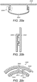
- FIGS 20A and 20B One possible arrangement is shown in Figures 20A and 20B .
- a dispenser 2008 of an aspect not forming part of the claimed invention is provided on the underside of a lid 2006 of a waste storage device.
- a powder comprising antibacterial and/or anti odour agent can be stored in the dispenser 2008.
- vents or holes may be provided in the surface of the dispenser 2008 as described above with respect to the other arrangements, in order for powder to be shaken out of the dispenser 2008.
- the dispenser 2008 in Figure 20A attaches to an underside of the lid 2006 via a screw mechanism 2004.
- the screw mechanism 2004 includes a large spaced thread as shown in more detail in Figure 20B .
- the dispenser 2008 whilst the lid 2006 and dispenser 2008 are reliably attached to one another via the screw mechanism 2004, it is possible for the dispenser to move up and down a distance 'd' with respect to the lid 2006 to which it is affixed. Therefore when the dispenser is directly knocked or shaken it can wobble or vibrate with respect to the lid 2006. Such wobbling or vibration can cause powder to be shaken out of the dispenser 2008 into the waste storage device therebelow.
- Figure 20C depicts an optional improvement of the arrangement shown in Figures 20A and 20B which is an aspect not forming part of the claimed invention,.
- the screw mechanism 2004 includes a female thread 2009 on the dispenser 2008 and a male thread 2011 on the lid 2006. It further includes an inward protrusion 2010 protruding inwardly from the female thread 2009 and an outward protrusion 2012 protruding outwardly from the male thread 2011.
- These protrusions 2010, 2012 form a lock for the screw mechanism 2004. They therefore secure the dispenser 2008 to the lid 2006 while still allowing for relative vertical movement therebetween.
- the user turns the screw thread past the interference of the two protrusions 2010, 2012 but no further.
- the user is therefore given tactile feedback regarding the locking point of the screw mechanism 2004, and at the same time is given a warning that the screw mechanism 2004 should not be tightened any further, so as to maintain the potential for vertical displacement in the screw mechanism 2004.
- protrusions in Figure 20C project radially, it is also possible to provide protrusions which extend in the axial direction in order to provide a similar interference and tactile feedback for locking of the dispenser to the lid of a waste storage device.
- an interrupted thread may be provided between the lid 2006 and the dispenser 2008 in order to secure the two together but with some room for relative movement.
- a dispenser 2108 of an aspect not forming part of the claimed invention may affix to the lid 2106 of a waste storage device using a bayonet and spring mechanism, as shown in Figure 21 .
- This type of mechanism will be familiar to the skilled reader.
- the bayonet 2102 attachment ensures that the dispenser 2108 is securely locked into the lid 2106 but the spring 2104 will allow for relative movement between the dispenser 2108 and the lid 2106.
- the entire dispenser may be made from a non-rigid, flexible material so that the entire dispenser can deform in order to agitate powder therein and vent powder from the dispenser.
- the dispenser may be dimensioned and positioned so that it collides with the main body of a waste storage device and/or with a waste cassette or cartridge stored therein when the lid to which the dispenser is attached closes. Such a collision would distort the dispenser in order to distribute the powder from therein.
- the vents or holes on the surface of the dispenser can be shaped so that powder cannot escape therethrough except when the dispenser is distorted.
- the vent may be provided in two layers wherein the holes in each layer are not aligned with one another when the dispenser is in its undeformed state but do align with one another and thereby allow passage of powder therethrough when the dispenser is distorted
- FIGS 32a and 32b show another possible flexible dispenser 3200, of an aspect not forming part of the claimed invention.
- the vents 3202 therein are in the form of narrow slits in the wall of the flexible dispenser 3200.
- the dispenser 3200 is located on the under surface of the lid 3204 of a waste storage device and is arranged so that when the lid 3204 is in its closed position the dispenser 3204 collides with the main body 3206 of the waste storage device, thereby compressing the shape of the dispenser 3200.
- the dispenser could compress upon collision with a projection somewhere on the device during opening or closing of the lid 3204. Such compression distorts the slit vents 3202, causing them to open to allow powder to be released.
- the slit vents are shown high up on the surface of the dispenser in figures 32a and 32b but could be located anywhere on the dispenser, for example at the point of collision. They can also be of any appropriate length dependent on the dosing requirements for the powder or other agent inside the dispenser, bearing in mind that if the slit vents are too long they may not open sufficiently to dose out powder upon collision of the dispenser with the device.
- Figure 22 shows one possible arrangement for achieving this.
- the waste storage device 2200 therein includes a dispenser 2208 of an aspect not forming part of the claimed invention, affixed to the lid 2206 of the device. As shown therein, there is a gap in the lid 2206 through which the dispenser 2208 is inserted, extending downwardly towards the main body of the waste storage device 2200. In the arrangement shown in Figure 22 the dispenser 2208 engages with the lid 2206 via a push fit, however any suitable inter-engagement means may be used.
- the dispenser 2208 comprises a cap 2202 covering the substantially hollow body of the dispenser 2208. On an outer surface of the cap 2202 there is an actuator 2204.
- the actuator 2204 has a spindle 2216 extending downwardly therefrom, into the hollow body the dispenser 2208 underneath the lid 2206.
- the actuator 2204 can be used to rotate the spindle 2216 when the lid 2206 of the waste storage device is closed.
- the cap 2202 can be made from any suitable material and shape but ideally it should provide a tight but releasable fit with the gap or aperture in the lid 2206 so that the user can take the cap 2202 off to refill the dispenser. It should also fit closely to the spindle 2216 while still allowing the spindle 2216 to rotate.
- collector 2214 for collecting a portion of the powder 2210 that is stored in the dispenser 2208.
- the collector 2214 is disc-shaped when viewed from above, however, any suitable size and shape of collector 2214 may be used dependent on the size and shape of the dispenser 2208 and the size of the portion of powder that is to be distributed from the collector 2214.
- the opening 2218 at the base of the collector 2214 must be aligned with the opening 2212 at the base of the dispenser 2208. In practice this is achieved by rotating the collector 2214 about its central axis using the actuator 2204 and the spindle 2216.
- a feedback mechanism may be provided so that the user knows, when actuating the actuator 2204, when the two openings 2218, 2212 are aligned. Further feedback, such as tactile feedback and/or an audible click, can be provided so that the user can further rotate the collector 2214 until the two openings 2218, 2212 are completely out of alignment with one another at times when the user does not want powder from the dispenser 2208 to be distributed via the openings to the waste storage device below.
- a locking mechanism may further be provided so that the collector 2214 is locked with its opening 2218 out of alignment with the opening 2212 in the dispenser 2208, so that movement such as actuation of the lid 2206, or the device 2200 being knocked or moved does not cause distribution of the powered agent 2210 from the dispenser 2208 accidentally.
- the actuator 2204 as shown in Figure 22 may be provided in a number of different forms.
- it may comprise a rotatable handle wherein rotation of that handle imparts rotational movement onto the spindle 2216 and collector 2214. Markings may be provided on the rotatable handle to visually show the user when the collector 2214 is locked to prevent distribution of the powdered agent 2210 and when it is aligned so as to provide maximum distribution of the powdered agent 2210.
- the actuator 2204 may be depressible by the user in order to rotate the spindle 2216 and collector 2214. Such an arrangement requires a spring to translate the vertical depression of the actuator into rotational movement of the spindle 2216 and collector 2214. Mechanisms of this type are known.
- the opening 2218, 2212 in the collector 2214 and dispenser 2208 respectively may comprise fully opened channels or may include a mesh or grid in order to filter and therefore further dose distribution of powder from the dispenser 2208 out into the main body of the waste storage device 2200.
- the opening 2212 in the base of the dispenser 2208 may be selected so that the powder is distributed onto a selected area within the waste storage device, for example onto the flexible tubing drawn out from a waste storage cassette or cartridge housed within the device.
- the dispenser itself may be rotatable about its central axis so that, when the openings 2218, 2212 are aligned, the dosed powder is not distributed only at one point but is instead distributed across a larger defined area within the waste storage device 2200.
- Figure 23 shows a top view of a collector, of an aspect not forming part of the claimed invention, wherein the collector 2314 is circular in cross-section and wherein the opening 2318 in the base of the collector 2314 comprises one quarter of the circular cross- section.
- FIG. 24 An alternative arrangement of an aspect not forming part of the claimed invention, is shown in Figure 24 wherein the collector 2414 comprises first 2418 and second 2420 open portions in its base. Therefore there are two rotational positions of this collector 2414 within a dispenser that provides a passageway from the powder in the dispenser to the waste storage device therebelow to be fully open.
- any collector having an opening in its base, during rotation of the collector from a closed position to a fully open position it will go through a partially open state wherein some of the opening at the base of the collector is aligned with the opening at the base of the dispenser, thereby allowing some powder to pass therethrough.
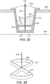
- Figure 25 shows an arrangement of an aspect not forming part of the claimed invention, including all the features described above with respect to Figure 22 and an additional shelf 2520 provided in the dispenser 2508, just above the collector 2514.
- the shelf 2520 comprises an opening 2522 therein. That opening 2522 in the shelf 2520 is out of alignment with the opening 2512 at the base of the dispenser but it can align with the opening 2518 at the base of the collector 2514, as shown in Figure 25 .
- it in order to fully lock the collector 2514, it must be rotated via the actuator 2504 and spindle 2516 so that the opening 2518 therein is out of alignment both with the opening 2522 in the shelf 2520 and the opening 2512
- rotation of the collector 2514 from a fully closed to a fully open state is a two stage process.
- the collector 2514 is rotated to align its opening 2518 with the opening 2522 in the shelf 2520, so that powder 2510 in the dispenser 2508 can fall through into the portion of the collector 2514 which has an opening at its base.
- the powder 2510 can comprise an antibacterial and/or an anti odour agent.
- the collector 2514 is rotated again in order to align the opening 2518 at its base with the opening 2512 in the base of the dispenser 2508. As a result, powder in the collector will drop through the base of the dispenser 2508 into the body of the waste storage device 2500 therebelow.
- FIG. 26 shows a possible collector 2614 of this type, which is an aspect not forming part of the claimed invention, comprising first 2618 and second 2620 collector portions, each having an open base, and no closed base portions. To lock such a collector 2614 the spindle 2616 should be rotated so that neither open collector portion 2618, 2620 is aligned with the opening at the base of the dispenser therebelow.
- the collector should be arranged within the dispenser so that the base of the dispenser lies flush with, or at least very close to, the base of the dispenser. Such an alignment will ensure that little or no powder can escape through the opening in the base of the collector back into the body of the dispenser when the collector is in a locked position.
- the dispenser has at least enough powder therein in order to cover the collector, downward pressure of the powder will ensure that any powder which escapes out of the hole in the base of the collector when it is in a locked position will be replaced by more powder from the dispenser above the collector.
- the inside of the dispenser can include a marking to show the minimum fill level of powder therein.
- the size of the collector and in particular the size of the open portion of the collector that will align with an opening at the base of the dispenser, is known, the amount of powder that will be dosed out of the dispenser each time the hole in the collector is aligned with the hole in the base of dispenser is also known. Therefore a controlled system for distributing powder comprising an antibacterial and/or an anti odour agent within a waste storage device is provided.
- collector 2514 shown in Figure 25 can be replaced by a conduit that can be positioned to provide a flow path for powder from the opening 2522 in the shelf 2520 down to the opening 2512 in the base of the dispenser 2508 for powder distribution.
- the conduit can then be rotated to remove the path between the two openings and to provide a blockade therebetween.
- the conduit may comprise a corkscrew to provide a more controlled path for the powder, rather than having a direct point-to-point flow path between the two openings 2522, 2512.
- a collector instead of rotating a collector to distribute powder out of a dispenser, linear movement of a plunger or other actuator can be used to push powder out of the dispenser.
- the plunger can be arranged to push a predetermined amount of powder out of the dispenser per actuation, hence providing a dosing effect.
- a collector instead of rotating about a central vertical axis, a collector may be provided which rotates about a horizontal axis in order to empty a dosed amount of powder out of the dispenser.
- Such a collector would be open at the top end, as per the collector as described with respect to Figures 22-26 , but need not have any opening in its base. Instead, in operation the collector would be rotated upside down to empty powder out of its top end through the opening in the base of the dispenser.
- the collectors depicted in Figures 22-26 are substantially circular in cross-section. However any suitable cross-sectional shape of collector may be used.
- the opening is in the base of the dispenser. However, it is possible to provide an opening in the side of the dispenser.
- the collector may be actuated in a suitable manner in order to dispense powder out of the opening in the side of the dispenser. For example, an open bottomed portion of the collector may be slid or otherwise translated out of the slot at the side of the dispenser, in order to empty the powder therein onto the waste storage device therebelow.
- the dispenser itself may be rotatable or otherwise movable in order to increase the distribution area for the powder.
- the distribution area may be chosen so that powder comprising antibacterial and/or anti odour agent is distributed onto a selected portion of the waste storage device and/or onto a waste storage cassette or cartridge stored therein.
- a cartridge or waste storage cassette is provided herein according to an example not claimed .
- FIG. 27 An example of such a cartridge is shown in Figure 27 .
- the cartridge 2700 comprises a ring 2702 at its top end and a bag 2704 or length of tubing extending downwardly therefrom.
- the ring 2702 is relatively rigid whilst the bag 2704 or tubing is relatively flexible yet strong enough to hold a number of items of waste.
- the ring comprises two folds or hinges 2706, positioned substantially diametrically opposite one another on the surface of the ring 2702 and each extending across the width of the ring 2702 at their respective locations.
- the ring 2702 can be folded about these hinges 2706 to bring the two halves of the ring together and thereby close the top of the bag 2704.
- Any suitable means for enabling reliable closure of the ring 2702 may be provided.
- a rib 2708 and cooperating recess 2710 are provided.
- the bag 2704 is generally welded to the underside of the ring 2702.
- the ring In use, the ring is folded upwards in order to close the top of the bag.
- a problem with such an arrangement is that the weld cannot be continuous as it is not possible to weld the bag onto the hinge.
- a small hole 2712 at either side of the folded ring As shown in Figure 28 herein.
- Such holes will allow odours from the bag to escape therethrough. This is a significant problem for users particularly when the cartridge 2700 is being used to store and dispose of waste such as used nappies or diapers.
- the weld 2714 between the bag 2704 and the underside of the ring 2702 in prior art arrangements must be sufficiently strong to withstand all the weight in the bag when it is filled. Because of this requirement, in prior art arrangements the weld 2714 must be located relatively near to the outer edge of the ring 2702, in order to increase the surface area, and hence the strength, of the weld 2714. The portion of the bag 2704 that is welded to the underside of the ring 2702 is effectively wasted, since it cannot be used to hold or wrap waste packages. Furthermore, in order for the ring 2702 in the prior art arrangements to close, the bag 2704 cannot be filled too much, hence again wasting bag material.
- a waste cartridge according to an example not claimed is shown in Figure 29 .
- the cartridge 2900 comprises a relatively rigid ring 2902 at its upper end and a bag 2904 of relatively flexible material extending downwardly therefrom.
- a length of open tubing that can be tied at its distal end may extend from the ring 2902.
- the bag 2904 as shown in Figure 29 is attached to an upper surface of the ring 2902.
- the bag 2904 attaches to the ring 2902 by welding.
- First 2914 and second 2916 welds are shown on the upper surface of the ring 2902 in Figure 29 .
- each weld 2914, 2916 extends only along a relatively small portion of a circumference on the upper surface of the ring 2902.
- the two welds 2914, 2916 do not extend in order to meet one another. Therefore the bag 2904 is only welded to the ring 2902 along part of its upper circumference. A significant portion of the top of the bag is not welded to the ring 2902 at all.
- Folds or hinges 2906 are provided in the ring 2902.
- the hinges 2906 are positioned substantially diametrically opposite one another on the ring 2902, each extending across the width of the ring 2902 at their respective locations.
- the hinges 2906 are positioned away from the weld 2914, 2916 on the upper surface of the ring 2902. Therefore, rather than providing a minimally small discontinuity in the weld in the vicinity of the hinges 2906, in the cartridge described herein there is a significant and deliberate discontinuity in the weld between the bag 2904 and the ring 2902, in order to leave a significant region unwelded around the hinges 2906.
- the folds or hinges 2906 are arranged so that the ring 2902 is folded downwards in order to seal the top of the bag 2904 in the waste cartridge. This can be seen more clearly from Figures 30 and 31 .
- Mechanical means for biasing a hinge in a certain direction are well known so will not be described in more detail herein. Because the bag is only welded to a portion of the ring well away from the hinges 2906, when the ring 2902 is folded downwards in this manner the top of the bag will naturally fall away from the hinge areas thereby not interfering with closure of the ring 2902.
- a rib 2908 and recess 2910 arrangement is provided on either side of each hinge 2906 in the waste cartridge 2900.
- the rib 2908 and recess 2910 cooperate with one another so that, when the ring 2902 is folded about the hinges 2906, the rib 2908 inter-engages with the recess 2910 in order to firmly close the ring 2902.
- the rib 2908 and recess 2910 arrangements are provided on the under surface of the ring 2902, in the vicinity of the ends of the welds 2914, 2916 so that when the ring 2902 is folded downwards and the bag 2904 naturally falls away from the ring 2904 except in the welded regions, inter-engagement of the ribs 2908 and recesses 2910 effectively traps any loose portions of the bag at its upper end, therefore enhancing the seal provided by closure of the ring 2902.
- the ring simply comprises weakened regions which allow the ring to be bent by .180°.
- ribs and recesses are used in the cassette shown in Figure 29 in order to enhance the sealing of the ring 2902 therein, it is possible to use alternative inter-engagement means such as any suitable pins, lugs or grooves which help to lock the two sides of the ring together in the folded state.
- the bag is only welded to the ring along a small portion of its surface and because the exact position of the weld does not determine the quality of the seal when the ring is folded, the welding process can be quicker. The welding will also be more cost-effective as there will be fewer rejected products because weld accuracy is not vital due to the fact that the final seal of the folded ring is achieved by the interengagement of ribs 2908 and recesses 2910. Also because the bag welds to an upper surface of the ring, the weld can be located closer to the inner edge of the ring, thereby requiring a smaller surface area of bag to be welded to the ring.
- the bag is only welded to the ring along two limited portions of its surface, and can therefore naturally fall away from the ring when it is folded, the bag can be filled with waste to quite a high level without causing stress on the weld regions with closure of the ring.
- the cartridge can hold more waste than prior art cartridges and therefore needs to be replaced less often. Thus, it is more convenient and cost-effective for the user.
- the ring is closed in order to seal the top of the bag, there are no gaps or holes through which odour can escape. Instead, the material of the bag is tightly pressed together by either side of the ring coming together and by the rib and recess or other arrangement provided to trap the bag material away from the hinges on the ring. The user can ensure this happens by tucking any loose portions of the top of the bag into the trapping arrangement whilst they are folding the ring. Therefore, a hygienic and odour-free waste storage system can be provided.
- the waste cartridge can be used in conjunction with a variety of waste storage devices.
- a waste storage device comprising a gripping means for gripping a portion of the bag below the ring, in order to seal the bag temporarily between successive deposits of waste packages therein.
- the cartridge may be used in conjunction with a waste storage device that twists a portion of the bag in order to provide a barrier between a stored waste package and the next waste package that is to be inserted into the bag.
- the ring and bag may be formed of any suitable material, including recycled material, such as plastic.
- the material may be bio-degradable.
- the bag and/or the ring may be impregnated with antibacterial and/or anti odour agent in order to further improve its operation.
- a waste storage device and a cartridge are provided. Whilst the waste storage device and cartridge have been described herein for use in disposing of used nappies or diapers, it will be appreciated that they can be used for storage of any waste material. Although not described herein, accumulated waste material may be removed from a waste storage device in any suitable manner for example using an opening at the base of the waste storage device and/or by separating upper and lower portions of the device from one another and removing the bag or tubing with accumulated waste therein from the device.
Landscapes
- Engineering & Computer Science (AREA)
- Mechanical Engineering (AREA)
- Refuse Receptacles (AREA)
- Closures For Containers (AREA)
- Processing Of Solid Wastes (AREA)
Applications Claiming Priority (2)
| Application Number | Priority Date | Filing Date | Title |
|---|---|---|---|
| GBGB1103429.5A GB201103429D0 (en) | 2011-02-28 | 2011-02-28 | Improved waste storage device and cassette |
| PCT/EP2012/053361 WO2012116986A2 (en) | 2011-02-28 | 2012-02-28 | Improved waste storage device and cassette |
Publications (2)
| Publication Number | Publication Date |
|---|---|
| EP2681136A2 EP2681136A2 (en) | 2014-01-08 |
| EP2681136B1 true EP2681136B1 (en) | 2021-01-06 |
Family
ID=43904325
Family Applications (1)
| Application Number | Title | Priority Date | Filing Date |
|---|---|---|---|
| EP12712970.8A Active EP2681136B1 (en) | 2011-02-28 | 2012-02-28 | Waste storage device |
Country Status (7)
| Country | Link |
|---|---|
| US (2) | US9428335B2 (da) |
| EP (1) | EP2681136B1 (da) |
| JP (2) | JP6035254B2 (da) |
| DK (1) | DK2681136T3 (da) |
| ES (1) | ES2859493T3 (da) |
| GB (1) | GB201103429D0 (da) |
| WO (1) | WO2012116986A2 (da) |
Families Citing this family (55)
| Publication number | Priority date | Publication date | Assignee | Title |
|---|---|---|---|---|
| US8720728B2 (en) | 2007-03-09 | 2014-05-13 | Simplehuman, Llc | Trash can |
| US9434538B2 (en) | 2010-03-12 | 2016-09-06 | Simplehuman, Llc | Trash can |
| GB201103429D0 (en) | 2011-02-28 | 2011-04-13 | Sangenic International Ltd | Improved waste storage device and cassette |
| US10279996B2 (en) | 2011-09-16 | 2019-05-07 | Simplehuman, Llc | Receptacle with low friction and low noise motion damper for lid |
| CA2808725C (en) | 2012-03-09 | 2020-03-24 | Simplehuman, Llc | Trash cans with features to aid in actuation |
| US9790025B2 (en) | 2012-03-09 | 2017-10-17 | Simplehuman, Llc | Trash can with clutch mechanism |
| USD695541S1 (en) * | 2012-10-24 | 2013-12-17 | Munchkin, Inc. | Cassette |
| US10279997B2 (en) | 2014-03-14 | 2019-05-07 | Simplehuman, Llc | Trash can assembly |
| US9856080B2 (en) | 2014-03-14 | 2018-01-02 | Simplehuman, Llc | Containers with multiple sensors |
| US9751692B2 (en) | 2014-03-14 | 2017-09-05 | Simplehuman, Llc | Dual sensing receptacles |
| CN103979239A (zh) * | 2014-05-10 | 2014-08-13 | 周维保 | 一种带垃圾袋的垃圾桶 |
| CN104016046B (zh) * | 2014-06-27 | 2016-04-20 | 谭翼翔 | 自动装袋式垃圾桶 |
| WO2016054109A1 (en) | 2014-10-01 | 2016-04-07 | Frank Yang | Trash cans |
| US10053284B2 (en) * | 2014-12-11 | 2018-08-21 | Munchkin, Inc. | Container for receiving multiple flexible bag assemblies |
| USD771344S1 (en) | 2015-03-05 | 2016-11-08 | Simplehuman, Llc | Trash can |
| USD759934S1 (en) | 2015-03-05 | 2016-06-21 | Simplehuman, Llc | Trash can trim component |
| US20160374455A1 (en) * | 2015-06-29 | 2016-12-29 | Gixia Group Co. | Cosmetic container with antibacterial protection |
| WO2017023965A1 (en) * | 2015-08-03 | 2017-02-09 | Rubbermaid Commercial Products Llc | Waste receptacle with pedal-operated lid |
| US9938069B2 (en) * | 2015-09-04 | 2018-04-10 | Casmiar Nwaigwe | Medical device sanitizer |
| GB201516048D0 (en) * | 2015-09-10 | 2015-10-28 | Sangenic International Ltd | Waste storage device |
| US12351390B2 (en) | 2015-09-16 | 2025-07-08 | Simplehuman, Llc | Containers with multiple sensors |
| US10029833B2 (en) * | 2015-11-05 | 2018-07-24 | Ningbo Easy Houseware Co., Ltd. | Quickly-sealing cover |
| US11242198B2 (en) | 2015-11-10 | 2022-02-08 | Simplehuman, Llc | Household goods with antimicrobial coatings and methods of making thereof |
| USD804133S1 (en) | 2015-12-09 | 2017-11-28 | Simplehuman, Llc | Trash can |
| WO2017132478A1 (en) * | 2016-01-28 | 2017-08-03 | Edgewell Personal Care Brands, Llc | Cassette with non-uniform liner cavity |
| US10494175B2 (en) | 2016-03-03 | 2019-12-03 | Simplehuman, Llc | Receptacle assemblies with motion dampers |
| USD793642S1 (en) | 2016-03-04 | 2017-08-01 | Simplehuman, Llc | Trash can |
| USD798016S1 (en) | 2016-03-04 | 2017-09-19 | Simplehuman, Llc | Trash can |
| AU201614012S (en) * | 2016-07-25 | 2016-08-01 | Mach IV Pty Ltd | Drum lid |
| AU2017251836B2 (en) * | 2016-10-28 | 2023-08-10 | Isabella SOMERS | A container |
| USD835376S1 (en) | 2016-11-14 | 2018-12-04 | Simplehuman, Llc | Trash can |
| US20180229932A1 (en) * | 2017-02-14 | 2018-08-16 | Steve DeGeorge | Trash receptacle system and method |
| US10317265B1 (en) | 2017-03-31 | 2019-06-11 | Pioneer Concepts, LLC | Trash receptacle granule dispenser |
| US10314930B1 (en) | 2017-03-31 | 2019-06-11 | Pioneer Concepts, LLC | Trash receptacle granule dispenser |
| USD837473S1 (en) | 2017-04-11 | 2019-01-01 | Magnuson Group, Inc. | Waste receptacle |
| CN206871754U (zh) * | 2017-04-21 | 2018-01-12 | 京东方科技集团股份有限公司 | 存储装置及收纳袋 |
| US10543982B2 (en) | 2017-05-23 | 2020-01-28 | Magnuson Group Inc. | Waste receptacle |
| USD855919S1 (en) | 2017-06-22 | 2019-08-06 | Simplehuman, Llc | Trash can |
| WO2019068237A1 (en) * | 2017-10-04 | 2019-04-11 | Global Mark Plastic Limited | ENHANCED CASSETTE FOR WASTE STORAGE SYSTEM |
| USD858923S1 (en) | 2018-01-12 | 2019-09-03 | Simplehuman, Llc | Trash can |
| USD858024S1 (en) | 2018-01-12 | 2019-08-27 | Simplehuman, Llc | Trash can |
| CA3035674C (en) | 2018-03-07 | 2026-01-20 | Simplehuman, Llc | Trash can assembly |
| KR200489107Y1 (ko) * | 2018-10-05 | 2019-05-02 | 이재윤 | 음식물 쓰레기 보관통 |
| CN109625679A (zh) * | 2018-12-29 | 2019-04-16 | 陈政 | 齿条传动式垃圾袋封口装置 |
| KR200489686Y1 (ko) * | 2019-01-14 | 2019-07-23 | 이재윤 | 음식물 쓰레기 보관통 |
| USD901815S1 (en) | 2019-05-16 | 2020-11-10 | Simplehuman, Llc | Slim trash can |
| IT202000003710A1 (it) * | 2020-02-21 | 2021-08-21 | Ernestomeda S P A | Dispositivo di trattamento dell’aria |
| CN111573053B (zh) * | 2020-04-07 | 2022-02-15 | 江苏大学 | 清洗型酸奶盒一体化高效回收装置 |
| USD963277S1 (en) | 2020-08-26 | 2022-09-06 | Simplehuman, Llc | Waste receptacle |
| USD969291S1 (en) | 2020-08-26 | 2022-11-08 | Simplehuman, Llc | Odor pod |
| CN116322805A (zh) * | 2020-10-09 | 2023-06-23 | 星球企业有限责任公司 | 用于室内和室外垃圾桶的一次性垫 |
| US12486106B2 (en) | 2020-10-09 | 2025-12-02 | Grote Industries Llc | Disposable pad for indoor and outdoor garbage cans, recyclables cans, compost bins, and other containers |
| USD1094941S1 (en) | 2022-06-03 | 2025-09-23 | Simplehuman, Llc | Waste receptacle |
| USD1072411S1 (en) | 2023-03-02 | 2025-04-22 | Simplehuman, Llc | Trash can |
| USD1072412S1 (en) | 2023-03-02 | 2025-04-22 | Simplehuman, Llc | Trash can |
Family Cites Families (160)
| Publication number | Priority date | Publication date | Assignee | Title |
|---|---|---|---|---|
| US412273A (en) * | 1889-10-08 | Commode | ||
| US1195034A (en) * | 1916-08-15 | Sanitary garbage receiver | ||
| US617961A (en) | 1899-01-17 | Bag-filler | ||
| GB106527A (da) * | ||||
| US435638A (en) | 1890-09-02 | Cortez e | ||
| US577747A (en) * | 1897-02-23 | Cover for pails | ||
| US182173A (en) | 1876-09-12 | Improvement in tobacco-bags | ||
| US918355A (en) | 1906-10-05 | 1909-04-13 | John Reed Mcgowan | Bag-holder. |
| GB453291A (en) | 1935-05-09 | 1936-09-09 | Albert Ernest Dutfield | Improvements relating to refuse containers such as dustbins |
| US2147139A (en) | 1936-03-11 | 1939-02-14 | Bigman Jacob | Refuse receptacle |
| US2434238A (en) * | 1945-11-10 | 1948-01-06 | Wolfson Sam | Combined container and dispenser |
| US2652173A (en) * | 1952-09-12 | 1953-09-15 | Universal Lubricating Systems | Germicidal receptacle |
| US2884162A (en) | 1954-05-03 | 1959-04-28 | Earl R Crebbs | Dispenser containers |
| US3214065A (en) | 1963-09-04 | 1965-10-26 | Goddard & Sons Ltd J | Powder dispensing devices |
| GB1105706A (en) | 1965-04-07 | 1968-03-13 | Thomas Loughrie | Improvements in or relating to dustbins and like containers |
| US3452368A (en) | 1966-10-07 | 1969-07-01 | Fts Corp | Portable waste disposer |
| US3682371A (en) | 1968-04-04 | 1972-08-08 | Keiji Saika | Packing tube |
| US3536192A (en) | 1969-02-17 | 1970-10-27 | John R Couper | Container for incremental withdraw of tubular plastic |
| US3732662A (en) | 1971-07-30 | 1973-05-15 | F Paxton | Method of forming, filling, closing and labelling tubular netting bags |
| US3746159A (en) | 1971-08-19 | 1973-07-17 | Coleman Co | Cartridge package for a sanitary toilet |
| SE401659B (sv) | 1972-03-09 | 1978-05-22 | Lovqvist Karl Bo Lennart | Anordning vid sopnedkast |
| US3938300A (en) | 1972-03-09 | 1976-02-17 | Karl Bo Lennart Lovqvist | Arrangement in refuse chutes |
| US3806984A (en) * | 1972-08-29 | 1974-04-30 | J Hilsabeck | Portable animal-excrement collector and disposal apparatus |
| SE381172B (sv) | 1973-01-03 | 1975-12-01 | Pactosan Ab | Anordning for paketering av avfall i en slang |
| GB1515266A (en) | 1973-12-01 | 1978-06-21 | Loughrie T | Containers |
| AR205194A1 (es) | 1974-05-08 | 1976-04-12 | Union Carbide Corp | Un material tubular flexible de pared delgada en largos autosostenidos para la industria frigorifica y metodo para su preparacion |
| US4132047A (en) | 1975-03-12 | 1979-01-02 | Hoechst Aktiengesellschaft | Method of making sheathed tubular stick |
| JPS5429272A (en) | 1977-08-08 | 1979-03-05 | Shibaura Eng Works Ltd | Disposer of sink |
| US4133356A (en) | 1977-08-26 | 1979-01-09 | Dillingham Julia E | Bag filling kit |
| GB0114312D0 (en) | 2001-06-12 | 2001-08-01 | Sangenic International Ltd | Spool for a waste storage device |
| US4191226A (en) | 1978-02-15 | 1980-03-04 | Kyte Garrett J | Basket filler |
| DE2809385A1 (de) | 1978-03-04 | 1979-09-06 | Hoechst Ag | Anordnung zum befuellen einer gerafften schlauchfoermigen huelle |
| FR2425384A1 (fr) | 1978-05-12 | 1979-12-07 | Scido | Dispositif pour le conditionnement d'objets dans une gaine tubulaire continue et comprenant un mecanisme d'entrainement positif de la gaine |
| US4422215A (en) | 1981-05-27 | 1983-12-27 | Teepak, Inc. | Sheathed hollow stick of shirred casing |
| SE437118B (sv) | 1981-07-03 | 1985-02-11 | Stiftelsen Klintland | Anordning for uppsamling av fast eller flytande avfall |
| DE3214673A1 (de) | 1982-04-21 | 1983-10-27 | Hoechst Ag, 6230 Frankfurt | Vorrichtung zur herstellung von gefuellten schlauchhuellen |
| US4488697A (en) | 1982-11-16 | 1984-12-18 | Garvey Norman G | Bag holder |
| JPS60136906A (ja) | 1983-12-26 | 1985-07-20 | Hitachi Ltd | 薄膜磁気ヘツドの製造方法 |
| JPS60136906U (ja) * | 1984-02-21 | 1985-09-11 | 佐藤 陸仁 | 屑物袋 |
| JPS63123701A (ja) | 1986-11-10 | 1988-05-27 | 太田 博康 | ゴミ自動パツク収容器の自動セツト用ゴミパツク製造装置 |
| GB8705120D0 (en) | 1987-03-05 | 1987-04-08 | Process Improvements Ltd | Packs of flexible tubing |
| EP0303517A1 (en) | 1987-08-13 | 1989-02-15 | van der Mescht, Leon | Apparatus for dispensing flexible tubing |
| DE3732033A1 (de) | 1987-09-23 | 1989-04-13 | Rovema Gmbh | Siegelvorrichtung |
| JPH01158404A (ja) | 1987-12-15 | 1989-06-21 | Sumitomo Electric Ind Ltd | プラスチッククラッド光ファイバー及びそのクラッド材料 |
| JPH01252402A (ja) | 1988-03-31 | 1989-10-09 | Toshiba Corp | ゴミ袋 |
| GB8818365D0 (en) | 1988-08-02 | 1988-09-07 | Process Improvements Ltd | Cassette containing flexible tubing to be dispensed therefrom |
| GB2221889A (en) | 1988-08-17 | 1990-02-21 | Process Improvements Ltd | Device for packaging objects in flexible tubing |
| DE8813273U1 (de) | 1988-10-22 | 1988-12-15 | Hoechst Ag, 6230 Frankfurt | Geraffter Verpackungsschlauch |
| DE3907488A1 (de) | 1989-03-08 | 1990-09-13 | Guenter Kollross | Verfahren zum verpacken eines zu einer hohlzylindrischen raupe gerafften schlauchhuellenabschnittes in ein schlauchnetz fuer die spaetere verarbeitung als wursthuelle auf einem wurstfuellautomaten |
| GB2232951B (en) | 1989-06-19 | 1993-02-24 | Process Improvements Ltd | Apparatus for producing layered tubes or rings |
| JPH04164701A (ja) * | 1990-10-30 | 1992-06-10 | Chizuko Ito | 補強口付汚物処理袋 |
| ATE143233T1 (de) | 1991-03-19 | 1996-10-15 | Bwm Import & Export | Stehtisch mit einem sich konisch verjüngenden standfuss |
| AU644282B2 (en) | 1991-05-27 | 1993-12-02 | Odour Control Systems Australia Pty Limited | Deodorizer dispenser |
| FR2698025B1 (fr) | 1992-11-13 | 1994-12-16 | Innovation Ingenierie Integrat | Dispositif de récupération et de stockage de déchets. |
| JPH079804A (ja) | 1993-06-29 | 1995-01-13 | Toogo:Kk | 軌道走行式遊戯用乗物の車輪装置 |
| JPH0728104A (ja) | 1993-07-13 | 1995-01-31 | Oki Electric Ind Co Ltd | 光変調素子 |
| JP3287914B2 (ja) | 1993-07-13 | 2002-06-04 | アップリカ▲葛▼西株式会社 | 汚物処理装置 |
| JP3287929B2 (ja) | 1993-11-05 | 2002-06-04 | アップリカ▲葛▼西株式会社 | 汚物処理装置 |
| DE9319683U1 (de) | 1993-12-21 | 1994-04-28 | Kreth Julius | Vorrichtung zum Verpacken von Abfällen |
| WO1996002282A1 (en) | 1994-07-13 | 1996-02-01 | Castlegate Trading Limited | A closure member |
| GB2292725B (en) | 1994-08-26 | 1998-04-15 | Process Improvements 1989 Ltd | Apparatus for using packs of flexible tubing in packaging |
| US5655680A (en) | 1994-10-20 | 1997-08-12 | Fisher Price, Inc. | Odorless container |
| US5535913A (en) | 1994-10-20 | 1996-07-16 | Fisher-Price, Inc. | Odorless container |
| JP3337848B2 (ja) | 1995-02-10 | 2002-10-28 | アップリカ▲葛▼西株式会社 | 汚物処理器 |
| JP3362297B2 (ja) * | 1995-04-06 | 2003-01-07 | 今村 清 | 汚物処理バッグの製造方法 |
| ES2108633B1 (es) | 1995-04-20 | 1998-07-01 | Daumar Talleres | Maquina para obtener bolsas llenas con productos a partir de lotes de malla tubular. |
| US6065272A (en) | 1995-11-17 | 2000-05-23 | Captiva Holding | Device for collecting and confining hospital and household waste |
| WO1997039673A1 (fr) | 1996-04-24 | 1997-10-30 | Englong He | Toilettes sans eau et entierement automatiques |
| US5782061A (en) | 1996-06-28 | 1998-07-21 | Free-Flow Packaging International, Inc. | System and method for making cushions of loose fill packing material |
| US5899049A (en) | 1996-06-28 | 1999-05-04 | Free-Flow Packaging International, Inc. | System and method for making cushions of loose fill packing material |
| GB9621864D0 (en) | 1996-10-21 | 1996-12-11 | Process Improvements 1989 Ltd | Apparatus for packaging packs of odorous waste in flexible tubing |
| DE19646165A1 (de) | 1996-11-08 | 1998-05-20 | Tils Peter | Verfahren zum Raffen von schlauchförmigen Verpackungsmaterialien, insbesondere Verpackungsfolien, und Vorrichtung zur Durchführung des Verfahrens |
| US5813200A (en) | 1996-12-17 | 1998-09-29 | Mondial Industries, Ltd. | Packaging and disposal system |
| US5871037A (en) | 1997-10-29 | 1999-02-16 | Feldt; Richard W. | Collapsible bag filler for assisting in the filling of waste bags |
| JP3048640U (ja) * | 1997-11-05 | 1998-05-22 | 美佳 湯本 | 使い捨て汚物入れ |
| JP3051256U (ja) * | 1997-11-25 | 1998-08-21 | 株式会社トクヤマ | 消臭剤用容器及び消臭剤収納部付の生ゴミ用容器 |
| GB9802738D0 (en) | 1998-02-09 | 1998-04-08 | Sangenic International Ltd | Waste storage device |
| DE19826082A1 (de) | 1998-06-12 | 1999-12-16 | Tils Peter | Verfahren zum Verpacken von zu entsorgendem Gut wie beispielsweise Hausmüll oder Speiseresten |
| IL124958A0 (en) | 1998-06-16 | 1999-01-26 | Yodfat Ofer | Implantable blood filtering device |
| US6116780A (en) | 1999-01-20 | 2000-09-12 | American Innotek, Inc. | Disposable toilet system |
| JP2000247401A (ja) | 1999-02-25 | 2000-09-12 | Biotech Research:Kk | 使用済み紙おむつ等貯留容器 |
| GB9908206D0 (en) | 1999-04-09 | 1999-06-02 | Sangenic International Limited | Waste storage device |
| CA2305999A1 (en) * | 1999-04-19 | 2000-10-19 | Fres-Co System Usa, Inc. | Pour-spout closure for flexible packages and flexible packages including a pour-spout closure |
| US7396444B2 (en) | 1999-06-22 | 2008-07-08 | Agilent Technologies Inc. | Device to operate a laboratory microchip |
| CN2417149Y (zh) | 2000-03-21 | 2001-01-31 | 陈宗仁 | 一种垃圾筒 |
| EP1136357A1 (de) | 2000-03-24 | 2001-09-26 | Tils, Peter | Verfahren zum Verpacken von Abfällen und Vorrichtung zur Durchführung des Verfahrens |
| EP1364879A3 (en) | 2000-09-07 | 2003-12-10 | Karl-Erik Wessmann | Apparatus for separately sealing a number of objects |
| US6370847B1 (en) | 2000-10-02 | 2002-04-16 | Tim Allan Nygaard Jensen | Sealable diaper-disposal system and method |
| US20020078665A1 (en) | 2000-12-21 | 2002-06-27 | Salman Nabil Enrique | Portable packaging device and method for forming individually packaged articles |
| JP4886113B2 (ja) | 2001-01-26 | 2012-02-29 | アップリカ・チルドレンズプロダクツ株式会社 | おむつ処理器 |
| US20050044819A1 (en) | 2003-09-02 | 2005-03-03 | Chomik Richard S. | Waste storage device |
| WO2002083525A1 (en) | 2001-04-10 | 2002-10-24 | Playtex Products, Inc. | Waste storage device |
| US7316100B2 (en) | 2001-05-02 | 2008-01-08 | Playtex Products, Inc. | Waste disposal device including a film cutting and sealing device |
| US7503152B2 (en) | 2001-05-02 | 2009-03-17 | Playtex Products, Inc. | Waste disposal device including rotating cartridge coupled to lid |
| US7958704B2 (en) | 2001-05-02 | 2011-06-14 | Playtex Products, Inc. | Waste disposal device including a mechanism for scoring a flexible tubing dispensed from a cartridge |
| US7503159B2 (en) | 2001-05-02 | 2009-03-17 | Playtex Products, Inc. | Waste disposal device including an external actuation mechanism to operate a cartridge |
| US7146785B2 (en) | 2001-05-02 | 2006-12-12 | Stravitz David M | Waste disposal devices |
| US7708188B2 (en) | 2001-05-02 | 2010-05-04 | Playtex Products, Inc. | Waste disposal device including a hamper accessible through a movable door |
| US7434377B2 (en) | 2001-05-02 | 2008-10-14 | Playtex Products, Inc. | Waste disposal device including a rotatable geared rim to operate a cartridge |
| US8091325B2 (en) | 2001-05-02 | 2012-01-10 | Playtex Products, Inc. | Waste disposal device including a diaphragm for twisting a flexible tubing dispensed from a cartridge |
| US7694493B2 (en) | 2001-05-02 | 2010-04-13 | Playtex Products, Inc. | Waste disposal device including a geared rotating cartridge |
| US7617659B2 (en) | 2001-05-02 | 2009-11-17 | Playtex Products, Inc. | Waste disposal device including a cartridge movable by rollers |
| US7712285B2 (en) | 2001-05-02 | 2010-05-11 | Playtex Products, Inc. | Waste disposal device including a sensing mechanism for delaying the rotation of a cartridge |
| CA2446103A1 (en) | 2001-05-02 | 2002-11-07 | Saniquest Industries Corp. | Waste disposal devices |
| US20050193692A1 (en) | 2001-05-02 | 2005-09-08 | Playtex Products, Inc. | Waste disposal device including rotating cartridge coupled to hinged lid |
| US6766817B2 (en) | 2001-07-25 | 2004-07-27 | Tubarc Technologies, Llc | Fluid conduction utilizing a reversible unsaturated siphon with tubarc porosity action |
| JP3994407B2 (ja) | 2001-10-16 | 2007-10-17 | アイリスショーワ株式会社 | 廃棄物収納容器 |
| CA2387183C (en) | 2001-12-31 | 2009-05-12 | Moniteurs Angelcare Inc. | Cassette for dispensing pleated tubing |
| CA2366384A1 (en) | 2001-12-31 | 2003-06-30 | Moniteurs Angelcare Inc. | Casssette for dispensing pleated tubing |
| US20030131569A1 (en) | 2002-01-02 | 2003-07-17 | Playtex Products, Inc. | Odor control cassette |
| CA2372143A1 (en) | 2002-02-15 | 2003-08-15 | Les Developpements Angelcare Inc. | Apparatus for forming and containing waste containing packs |
| MXPA04007360A (es) | 2002-04-17 | 2004-11-26 | Playtex Products Inc | Cassette desechable para retirar de manera incremental plastico tubular con capacidad para contrarrestar el mal olor. |
| CA2383799A1 (en) | 2002-04-26 | 2003-10-26 | Moniteurs Angelcare Inc./ Angelcare Monitors Inc. | Apparatus for packaging objects to be disposed of into pouches formed along a tube of plastic material |
| US6958132B2 (en) | 2002-05-31 | 2005-10-25 | The Regents Of The University Of California | Systems and methods for optical actuation of microfluidics based on opto-electrowetting |
| CN2543475Y (zh) | 2002-06-07 | 2003-04-09 | 雷祖荫 | 无水洁便器 |
| FR2841229B1 (fr) | 2002-06-19 | 2006-05-26 | Aa Man | Dispositif de collecte de dechets |
| EP1545807A2 (en) | 2002-07-31 | 2005-06-29 | David M. Stravitz | Waste disposal device |
| CA2412431A1 (en) | 2002-11-20 | 2004-05-20 | Louis Lefebvre | Apparatus for packing objects into an elongated tube |
| JP3774429B2 (ja) | 2002-11-27 | 2006-05-17 | 株式会社グリーンライフ | 廃棄物処理装置 |
| US6672472B1 (en) | 2003-02-14 | 2004-01-06 | Elayne D. Rockwood | Soiled clothing container |
| US6941733B2 (en) | 2003-04-03 | 2005-09-13 | Playtex Products, Inc. | Waste disposal apparatus |
| GB0324764D0 (en) | 2003-10-23 | 2003-11-26 | Sangenic International Ltd | Waste storage device |
| US6925781B1 (en) | 2004-02-03 | 2005-08-09 | Playtex Products, Inc. | Integrated cutting tool for waste disposal method and apparatus |
| WO2005083390A1 (en) | 2004-02-20 | 2005-09-09 | Research Foundation Of The State University Of New York | Method and device for manipulating liquids in microfluidic systems |
| US6993891B2 (en) | 2004-04-03 | 2006-02-07 | Bobbi Sue Richardson | Waste disposal system with flexible tubing |
| CN2714475Y (zh) | 2004-07-02 | 2005-08-03 | 林恒兴 | 具有光圈式上盖组件的容器 |
| CA2579165C (en) | 2004-09-02 | 2010-05-11 | Playtex Products, Inc. | Waste disposal device including a cartridge |
| WO2006029039A1 (en) | 2004-09-02 | 2006-03-16 | Playtex Products, Inc. | Waste disposal device including an external actuatino mechanism to operate a cartridge |
| GB2444867B (en) | 2004-09-02 | 2008-11-26 | Playtex Products Inc | Waste disposal Device |
| CA2791742C (en) | 2004-09-02 | 2017-07-04 | Playtex Products, Llc | Waste disposal apparatus |
| EP1658897A1 (en) | 2004-11-22 | 2006-05-24 | Roche Diagnostics GmbH | Bent microfluidic device |
| US7406814B2 (en) | 2005-04-25 | 2008-08-05 | International Refills Company Ltd. | Apparatus for packing disposable objects into an elongated tube of flexible material |
| CN2882503Y (zh) | 2005-06-20 | 2007-03-28 | 尹滋 | 便携式打包座便装置 |
| CA2518325C (en) | 2005-09-07 | 2013-01-22 | Les Developpements Angelcare Inc. | Apparatus for forming waste containing packs |
| CN1931683B (zh) | 2005-09-14 | 2011-06-08 | 香港肯比科拉夫企业有限公司 | 一种污染物的贮运装置 |
| DE202005015117U1 (de) | 2005-09-24 | 2007-02-15 | Melitta Haushaltsprodukte Gmbh & Co. Kg | Vorrichtung zum Verpacken von Hygieneartikeln |
| CN101016113A (zh) | 2005-11-03 | 2007-08-15 | 哥瑞考儿童产品公司 | 免接触尿布桶 |
| CN2861082Y (zh) | 2005-12-14 | 2007-01-24 | 卢凌戈 | 可连续自动套袋自动打包垃圾桶 |
| DE202006004159U1 (de) | 2006-03-16 | 2007-08-02 | Melitta Haushaltsprodukte Gmbh & Co Kommanditgesellschaft | Vorrichtung zum Entsorgen von Hygieneartikeln |
| US8501117B1 (en) | 2006-06-05 | 2013-08-06 | Carnegie Mellon University | Apparatuses, systems, and methods utilizing capillary action |
| GB0622909D0 (en) | 2006-11-16 | 2006-12-27 | Sangenic International Ltd | Waste storage device |
| US20080272140A1 (en) | 2007-05-04 | 2008-11-06 | Playtex Products, Inc. | Cassette for dispensing flexible tubing therefrom |
| DE202007009842U1 (de) | 2007-07-12 | 2008-11-20 | Sangenic International Ltd., Cramlington | Verbesserte Kassette für eine Abfallaufbewahrungsvorrichtung |
| EP2818430B1 (en) | 2007-10-05 | 2020-05-06 | International Refills Company Limited | Cassette for dispensing bags from an elongated tubing |
| US20090126320A1 (en) | 2007-11-16 | 2009-05-21 | Playtex Products, Inc. | Waste disposal devices and methods |
| KR101353972B1 (ko) | 2008-05-19 | 2014-01-22 | 산제닉 인터내셔날 리미티드 | 폐기물 저장 장치 |
| US20220228811A9 (en) | 2008-07-21 | 2022-07-21 | The Regents Of The University Of California | Titanium-based thermal ground plane |
| KR20110089280A (ko) | 2008-11-18 | 2011-08-05 | 존슨 컨트롤스 테크놀러지 컴퍼니 | 전력 저장 장치 |
| US8338187B2 (en) | 2009-03-13 | 2012-12-25 | Illumina, Inc. | Methods and systems for controlling liquids in multiplex assays |
| US8196909B2 (en) | 2009-04-30 | 2012-06-12 | Uop Llc | Tubular condensers having tubes with external enhancements |
| US8690017B2 (en) * | 2009-10-30 | 2014-04-08 | Munchkin, Inc. | Powder dispensing assembly for a waste container |
| US8567157B2 (en) * | 2009-10-30 | 2013-10-29 | Munchkin, Inc. | System for disposing waste packages such as diapers |
| US7878359B1 (en) | 2010-03-07 | 2011-02-01 | Wen-Hsiung Ko | Trash can with a deodorizing mechanism |
| JP3159649U (ja) * | 2010-03-10 | 2010-05-27 | 柯 文雄 | ゴミ箱 |
| JP2012073068A (ja) | 2010-09-28 | 2012-04-12 | Fuji Electric Co Ltd | 圧力センサ用パッケージ |
| GB201103429D0 (en) | 2011-02-28 | 2011-04-13 | Sangenic International Ltd | Improved waste storage device and cassette |
| US8733348B2 (en) | 2011-09-30 | 2014-05-27 | Carefusion 207, Inc. | Humidifying respiratory gases |
| US9272113B2 (en) | 2012-03-30 | 2016-03-01 | Carefusion 207, Inc. | Transporting liquid in a respiratory component |
| US9549832B2 (en) | 2012-04-26 | 2017-01-24 | Medtronic Vascular, Inc. | Apparatus and methods for filling a drug eluting medical device via capillary action |
| JP2013248105A (ja) * | 2012-05-31 | 2013-12-12 | Eeson Enterprise Kk | 男女兼用ポケットトイレ |
-
2011
- 2011-02-28 GB GBGB1103429.5A patent/GB201103429D0/en not_active Ceased
-
2012
- 2012-02-28 ES ES12712970T patent/ES2859493T3/es active Active
- 2012-02-28 JP JP2013555849A patent/JP6035254B2/ja active Active
- 2012-02-28 US US14/002,072 patent/US9428335B2/en active Active
- 2012-02-28 WO PCT/EP2012/053361 patent/WO2012116986A2/en not_active Ceased
- 2012-02-28 DK DK12712970.8T patent/DK2681136T3/da active
- 2012-02-28 EP EP12712970.8A patent/EP2681136B1/en active Active
-
2016
- 2016-08-01 US US15/225,142 patent/US10214347B2/en active Active
- 2016-10-31 JP JP2016212744A patent/JP6465852B2/ja active Active
Non-Patent Citations (1)
| Title |
|---|
| None * |
Also Published As
| Publication number | Publication date |
|---|---|
| EP2681136A2 (en) | 2014-01-08 |
| WO2012116986A3 (en) | 2012-10-26 |
| US20140183193A1 (en) | 2014-07-03 |
| ES2859493T3 (es) | 2021-10-04 |
| JP6035254B2 (ja) | 2016-11-30 |
| JP2017052653A (ja) | 2017-03-16 |
| JP6465852B2 (ja) | 2019-02-06 |
| US20170029205A1 (en) | 2017-02-02 |
| WO2012116986A2 (en) | 2012-09-07 |
| GB201103429D0 (en) | 2011-04-13 |
| US10214347B2 (en) | 2019-02-26 |
| DK2681136T3 (da) | 2021-04-06 |
| JP2014511320A (ja) | 2014-05-15 |
| US9428335B2 (en) | 2016-08-30 |
Similar Documents
| Publication | Publication Date | Title |
|---|---|---|
| US10214347B2 (en) | Waste storage device | |
| CA2473693C (en) | Disposable cassette for incremental withdrawal of tubular plastic with malodor-counteractant capacity | |
| US2802590A (en) | Waste can compound cover and parts | |
| CA2814249C (en) | Automated twist diaper disposal apparatus | |
| US9994392B1 (en) | Unitary insert for waste containers | |
| US8528784B2 (en) | Spray bottle with refill cartridge | |
| US3214065A (en) | Powder dispensing devices | |
| US9573757B1 (en) | Waste treatment components | |
| US20150083755A1 (en) | Dispensing System with Bracket | |
| US7273184B2 (en) | Disposable air treatment device | |
| EP1765423B1 (en) | Container air freshener unit | |
| US20100155399A1 (en) | Automated insect deterrent pump spray applicator | |
| JP6012155B2 (ja) | 据え置き型定量噴霧装置、及びこれを用いた小空間への薬液散布方法 | |
| WO2014028824A1 (en) | Dispenser | |
| US20060049216A1 (en) | Self-orienting aerosol apparatus and method of cleaning a trash can | |
| EP2493785B1 (en) | Powder dispensing assembly for a waste container | |
| US20250198078A1 (en) | Deodorizing Laundry Hamper | |
| AU2006264217A1 (en) | Automated insect deterrent pump spray applicator | |
| KR20230084249A (ko) | 실내 및 실외 쓰레기통용 일회용 패드 |
Legal Events
| Date | Code | Title | Description |
|---|---|---|---|
| PUAI | Public reference made under article 153(3) epc to a published international application that has entered the european phase |
Free format text: ORIGINAL CODE: 0009012 |
|
| 17P | Request for examination filed |
Effective date: 20130919 |
|
| AK | Designated contracting states |
Kind code of ref document: A2 Designated state(s): AL AT BE BG CH CY CZ DE DK EE ES FI FR GB GR HR HU IE IS IT LI LT LU LV MC MK MT NL NO PL PT RO RS SE SI SK SM TR |
|
| DAX | Request for extension of the european patent (deleted) | ||
| STAA | Information on the status of an ep patent application or granted ep patent |
Free format text: STATUS: EXAMINATION IS IN PROGRESS |
|
| 17Q | First examination report despatched |
Effective date: 20180719 |
|
| RAP1 | Party data changed (applicant data changed or rights of an application transferred) |
Owner name: SANGENIC INTERNATIONAL LTD |
|
| GRAP | Despatch of communication of intention to grant a patent |
Free format text: ORIGINAL CODE: EPIDOSNIGR1 |
|
| STAA | Information on the status of an ep patent application or granted ep patent |
Free format text: STATUS: GRANT OF PATENT IS INTENDED |
|
| INTG | Intention to grant announced |
Effective date: 20200922 |
|
| GRAS | Grant fee paid |
Free format text: ORIGINAL CODE: EPIDOSNIGR3 |
|
| GRAA | (expected) grant |
Free format text: ORIGINAL CODE: 0009210 |
|
| STAA | Information on the status of an ep patent application or granted ep patent |
Free format text: STATUS: THE PATENT HAS BEEN GRANTED |
|
| AK | Designated contracting states |
Kind code of ref document: B1 Designated state(s): AL AT BE BG CH CY CZ DE DK EE ES FI FR GB GR HR HU IE IS IT LI LT LU LV MC MK MT NL NO PL PT RO RS SE SI SK SM TR |
|
| REG | Reference to a national code |
Ref country code: GB Ref legal event code: FG4D |
|
| REG | Reference to a national code |
Ref country code: AT Ref legal event code: REF Ref document number: 1352121 Country of ref document: AT Kind code of ref document: T Effective date: 20210115 Ref country code: CH Ref legal event code: EP |
|
| REG | Reference to a national code |
Ref country code: DE Ref legal event code: R096 Ref document number: 602012074012 Country of ref document: DE |
|
| REG | Reference to a national code |
Ref country code: IE Ref legal event code: FG4D |
|
| REG | Reference to a national code |
Ref country code: DK Ref legal event code: T3 Effective date: 20210331 |
|
| REG | Reference to a national code |
Ref country code: NO Ref legal event code: T2 Effective date: 20210106 |
|
| REG | Reference to a national code |
Ref country code: SE Ref legal event code: TRGR |
|
| REG | Reference to a national code |
Ref country code: NL Ref legal event code: MP Effective date: 20210106 |
|
| REG | Reference to a national code |
Ref country code: AT Ref legal event code: MK05 Ref document number: 1352121 Country of ref document: AT Kind code of ref document: T Effective date: 20210106 |
|
| REG | Reference to a national code |
Ref country code: LT Ref legal event code: MG9D |
|
| PG25 | Lapsed in a contracting state [announced via postgrant information from national office to epo] |
Ref country code: PT Free format text: LAPSE BECAUSE OF FAILURE TO SUBMIT A TRANSLATION OF THE DESCRIPTION OR TO PAY THE FEE WITHIN THE PRESCRIBED TIME-LIMIT Effective date: 20210506 Ref country code: LT Free format text: LAPSE BECAUSE OF FAILURE TO SUBMIT A TRANSLATION OF THE DESCRIPTION OR TO PAY THE FEE WITHIN THE PRESCRIBED TIME-LIMIT Effective date: 20210106 Ref country code: HR Free format text: LAPSE BECAUSE OF FAILURE TO SUBMIT A TRANSLATION OF THE DESCRIPTION OR TO PAY THE FEE WITHIN THE PRESCRIBED TIME-LIMIT Effective date: 20210106 Ref country code: GR Free format text: LAPSE BECAUSE OF FAILURE TO SUBMIT A TRANSLATION OF THE DESCRIPTION OR TO PAY THE FEE WITHIN THE PRESCRIBED TIME-LIMIT Effective date: 20210407 Ref country code: FI Free format text: LAPSE BECAUSE OF FAILURE TO SUBMIT A TRANSLATION OF THE DESCRIPTION OR TO PAY THE FEE WITHIN THE PRESCRIBED TIME-LIMIT Effective date: 20210106 Ref country code: BG Free format text: LAPSE BECAUSE OF FAILURE TO SUBMIT A TRANSLATION OF THE DESCRIPTION OR TO PAY THE FEE WITHIN THE PRESCRIBED TIME-LIMIT Effective date: 20210406 Ref country code: NL Free format text: LAPSE BECAUSE OF FAILURE TO SUBMIT A TRANSLATION OF THE DESCRIPTION OR TO PAY THE FEE WITHIN THE PRESCRIBED TIME-LIMIT Effective date: 20210106 |
|
| PG25 | Lapsed in a contracting state [announced via postgrant information from national office to epo] |
Ref country code: RS Free format text: LAPSE BECAUSE OF FAILURE TO SUBMIT A TRANSLATION OF THE DESCRIPTION OR TO PAY THE FEE WITHIN THE PRESCRIBED TIME-LIMIT Effective date: 20210106 Ref country code: PL Free format text: LAPSE BECAUSE OF FAILURE TO SUBMIT A TRANSLATION OF THE DESCRIPTION OR TO PAY THE FEE WITHIN THE PRESCRIBED TIME-LIMIT Effective date: 20210106 Ref country code: LV Free format text: LAPSE BECAUSE OF FAILURE TO SUBMIT A TRANSLATION OF THE DESCRIPTION OR TO PAY THE FEE WITHIN THE PRESCRIBED TIME-LIMIT Effective date: 20210106 Ref country code: AT Free format text: LAPSE BECAUSE OF FAILURE TO SUBMIT A TRANSLATION OF THE DESCRIPTION OR TO PAY THE FEE WITHIN THE PRESCRIBED TIME-LIMIT Effective date: 20210106 |
|
| PG25 | Lapsed in a contracting state [announced via postgrant information from national office to epo] |
Ref country code: IS Free format text: LAPSE BECAUSE OF FAILURE TO SUBMIT A TRANSLATION OF THE DESCRIPTION OR TO PAY THE FEE WITHIN THE PRESCRIBED TIME-LIMIT Effective date: 20210506 |
|
| REG | Reference to a national code |
Ref country code: ES Ref legal event code: FG2A Ref document number: 2859493 Country of ref document: ES Kind code of ref document: T3 Effective date: 20211004 |
|
| REG | Reference to a national code |
Ref country code: DE Ref legal event code: R097 Ref document number: 602012074012 Country of ref document: DE |
|
| REG | Reference to a national code |
Ref country code: BE Ref legal event code: MM Effective date: 20210228 |
|
| PG25 | Lapsed in a contracting state [announced via postgrant information from national office to epo] |
Ref country code: CH Free format text: LAPSE BECAUSE OF NON-PAYMENT OF DUE FEES Effective date: 20210228 Ref country code: SM Free format text: LAPSE BECAUSE OF FAILURE TO SUBMIT A TRANSLATION OF THE DESCRIPTION OR TO PAY THE FEE WITHIN THE PRESCRIBED TIME-LIMIT Effective date: 20210106 Ref country code: EE Free format text: LAPSE BECAUSE OF FAILURE TO SUBMIT A TRANSLATION OF THE DESCRIPTION OR TO PAY THE FEE WITHIN THE PRESCRIBED TIME-LIMIT Effective date: 20210106 Ref country code: CZ Free format text: LAPSE BECAUSE OF FAILURE TO SUBMIT A TRANSLATION OF THE DESCRIPTION OR TO PAY THE FEE WITHIN THE PRESCRIBED TIME-LIMIT Effective date: 20210106 Ref country code: LI Free format text: LAPSE BECAUSE OF NON-PAYMENT OF DUE FEES Effective date: 20210228 Ref country code: MC Free format text: LAPSE BECAUSE OF FAILURE TO SUBMIT A TRANSLATION OF THE DESCRIPTION OR TO PAY THE FEE WITHIN THE PRESCRIBED TIME-LIMIT Effective date: 20210106 Ref country code: LU Free format text: LAPSE BECAUSE OF NON-PAYMENT OF DUE FEES Effective date: 20210228 |
|
| PLBE | No opposition filed within time limit |
Free format text: ORIGINAL CODE: 0009261 |
|
| STAA | Information on the status of an ep patent application or granted ep patent |
Free format text: STATUS: NO OPPOSITION FILED WITHIN TIME LIMIT |
|
| PG25 | Lapsed in a contracting state [announced via postgrant information from national office to epo] |
Ref country code: SK Free format text: LAPSE BECAUSE OF FAILURE TO SUBMIT A TRANSLATION OF THE DESCRIPTION OR TO PAY THE FEE WITHIN THE PRESCRIBED TIME-LIMIT Effective date: 20210106 Ref country code: RO Free format text: LAPSE BECAUSE OF FAILURE TO SUBMIT A TRANSLATION OF THE DESCRIPTION OR TO PAY THE FEE WITHIN THE PRESCRIBED TIME-LIMIT Effective date: 20210106 |
|
| 26N | No opposition filed |
Effective date: 20211007 |
|
| PG25 | Lapsed in a contracting state [announced via postgrant information from national office to epo] |
Ref country code: IE Free format text: LAPSE BECAUSE OF NON-PAYMENT OF DUE FEES Effective date: 20210228 Ref country code: AL Free format text: LAPSE BECAUSE OF FAILURE TO SUBMIT A TRANSLATION OF THE DESCRIPTION OR TO PAY THE FEE WITHIN THE PRESCRIBED TIME-LIMIT Effective date: 20210106 |
|
| PG25 | Lapsed in a contracting state [announced via postgrant information from national office to epo] |
Ref country code: SI Free format text: LAPSE BECAUSE OF FAILURE TO SUBMIT A TRANSLATION OF THE DESCRIPTION OR TO PAY THE FEE WITHIN THE PRESCRIBED TIME-LIMIT Effective date: 20210106 |
|
| PG25 | Lapsed in a contracting state [announced via postgrant information from national office to epo] |
Ref country code: IS Free format text: LAPSE BECAUSE OF FAILURE TO SUBMIT A TRANSLATION OF THE DESCRIPTION OR TO PAY THE FEE WITHIN THE PRESCRIBED TIME-LIMIT Effective date: 20210506 |
|
| PG25 | Lapsed in a contracting state [announced via postgrant information from national office to epo] |
Ref country code: BE Free format text: LAPSE BECAUSE OF NON-PAYMENT OF DUE FEES Effective date: 20210228 |
|
| PG25 | Lapsed in a contracting state [announced via postgrant information from national office to epo] |
Ref country code: HU Free format text: LAPSE BECAUSE OF FAILURE TO SUBMIT A TRANSLATION OF THE DESCRIPTION OR TO PAY THE FEE WITHIN THE PRESCRIBED TIME-LIMIT; INVALID AB INITIO Effective date: 20120228 Ref country code: CY Free format text: LAPSE BECAUSE OF FAILURE TO SUBMIT A TRANSLATION OF THE DESCRIPTION OR TO PAY THE FEE WITHIN THE PRESCRIBED TIME-LIMIT Effective date: 20210106 |
|
| P01 | Opt-out of the competence of the unified patent court (upc) registered |
Effective date: 20230428 |
|
| PG25 | Lapsed in a contracting state [announced via postgrant information from national office to epo] |
Ref country code: MK Free format text: LAPSE BECAUSE OF FAILURE TO SUBMIT A TRANSLATION OF THE DESCRIPTION OR TO PAY THE FEE WITHIN THE PRESCRIBED TIME-LIMIT Effective date: 20210106 |
|
| PG25 | Lapsed in a contracting state [announced via postgrant information from national office to epo] |
Ref country code: TR Free format text: LAPSE BECAUSE OF FAILURE TO SUBMIT A TRANSLATION OF THE DESCRIPTION OR TO PAY THE FEE WITHIN THE PRESCRIBED TIME-LIMIT Effective date: 20210106 |
|
| PG25 | Lapsed in a contracting state [announced via postgrant information from national office to epo] |
Ref country code: MT Free format text: LAPSE BECAUSE OF FAILURE TO SUBMIT A TRANSLATION OF THE DESCRIPTION OR TO PAY THE FEE WITHIN THE PRESCRIBED TIME-LIMIT Effective date: 20210106 |
|
| PGFP | Annual fee paid to national office [announced via postgrant information from national office to epo] |
Ref country code: SE Payment date: 20260218 Year of fee payment: 15 |
|
| PGFP | Annual fee paid to national office [announced via postgrant information from national office to epo] |
Ref country code: GB Payment date: 20260219 Year of fee payment: 15 |
|
| PGFP | Annual fee paid to national office [announced via postgrant information from national office to epo] |
Ref country code: ES Payment date: 20260319 Year of fee payment: 15 |
|
| PGFP | Annual fee paid to national office [announced via postgrant information from national office to epo] |
Ref country code: NO Payment date: 20260217 Year of fee payment: 15 Ref country code: DK Payment date: 20260217 Year of fee payment: 15 Ref country code: DE Payment date: 20260217 Year of fee payment: 15 |
|
| PGFP | Annual fee paid to national office [announced via postgrant information from national office to epo] |
Ref country code: IT Payment date: 20260227 Year of fee payment: 15 |
|
| PGFP | Annual fee paid to national office [announced via postgrant information from national office to epo] |
Ref country code: FR Payment date: 20260219 Year of fee payment: 15 |