EP2681360B1 - Ensemble de cylindres a entrainement direct electromoteur et procede de montage - Google Patents
Ensemble de cylindres a entrainement direct electromoteur et procede de montage Download PDFInfo
- Publication number
- EP2681360B1 EP2681360B1 EP12701751.5A EP12701751A EP2681360B1 EP 2681360 B1 EP2681360 B1 EP 2681360B1 EP 12701751 A EP12701751 A EP 12701751A EP 2681360 B1 EP2681360 B1 EP 2681360B1
- Authority
- EP
- European Patent Office
- Prior art keywords
- roll
- stator
- axis
- rotation
- stator segments
- Prior art date
- Legal status (The legal status is an assumption and is not a legal conclusion. Google has not performed a legal analysis and makes no representation as to the accuracy of the status listed.)
- Active
Links
Images


Classifications
-
- D—TEXTILES; PAPER
- D21—PAPER-MAKING; PRODUCTION OF CELLULOSE
- D21G—CALENDERS; ACCESSORIES FOR PAPER-MAKING MACHINES
- D21G1/00—Calenders; Smoothing apparatus
- D21G1/0006—Driving arrangements
-
- B—PERFORMING OPERATIONS; TRANSPORTING
- B21—MECHANICAL METAL-WORKING WITHOUT ESSENTIALLY REMOVING MATERIAL; PUNCHING METAL
- B21B—ROLLING OF METAL
- B21B35/00—Drives for metal-rolling mills, e.g. hydraulic drives
- B21B35/06—Drives for metal-rolling mills, e.g. hydraulic drives for non-continuously-operating mills or for single stands
-
- D—TEXTILES; PAPER
- D21—PAPER-MAKING; PRODUCTION OF CELLULOSE
- D21G—CALENDERS; ACCESSORIES FOR PAPER-MAKING MACHINES
- D21G1/00—Calenders; Smoothing apparatus
- D21G1/0006—Driving arrangements
- D21G1/0013—Driving arrangements for controlled deflection rolls
-
- D—TEXTILES; PAPER
- D21—PAPER-MAKING; PRODUCTION OF CELLULOSE
- D21G—CALENDERS; ACCESSORIES FOR PAPER-MAKING MACHINES
- D21G1/00—Calenders; Smoothing apparatus
- D21G1/02—Rolls; Their bearings
- D21G1/0226—Bearings
Definitions
- the invention relates to a roller assembly, comprising a roller, which comprises an axle or shaft mounted on a bearing, with a roller body forming the working circumference of the roller, which is rotatable about a rotation axis, and with an electromotive direct drive, the rotor and the stator in the direction the axis of rotation between the bearing point and the roller body are arranged, and a mounting method for such a roller.
- Such a roller assembly is known from DE 103 39 733 A1 known.
- the rotor of the electromotive direct drive is firmly connected to a remote from the scope of the roll roll neck.
- the rotor of the annular gap leaving a stator of the electromotive direct drive is provided in a motor housing, which is supported by means of its own housing bearing on the axis of rotation of this roller defining shaft.
- For receiving reaction forces associated with a machine frame torque arm is provided, which is designed to avoid mechanical over-determination as an elastic element.
- the installation of such a roller assembly is quite significant problems.
- the rotor comprises an arrangement of strong permanent magnets. Because of this act strong magnetic radial forces between the stator and the rotor when joining, trying to bring the stator and rotor into abutment. However, this is to be avoided at all costs, as stators and rotors touching one another due to the attractive forces can be damaged or destroyed here. In addition, stators and rotors once brought into abutment can no longer be manually separated due to the high attraction forces.
- stator mounted together with the rotor - depending on the roll construction - the assembly of other components, such as those of the roller bearing and donor systems of the electromotive direct drive, be a hindrance.
- the invention is therefore based on the object to provide a respect to these disadvantages improved roller assembly and an improved assembly method.
- stator of the electromotive direct drive which is also referred to as “torque motor”, divided in at least one plane parallel to the axis of rotation or oblique plane in stator segments.
- plane inclined to the rotation axis it is meant that the planes in which the stator is divided into the stator segments do not necessarily have to run parallel to the axis of rotation, but may also be deviated therefrom to the extent that a division in the sense of separation of the otherwise closed Stator ring takes place.
- the roller in the roller arrangement according to the invention for setting up the bearing, the roller can be completely installed and stored in a bearing device before it comes to a joining operation of the rotor connected to the roller body and the stator.
- bearing means is to be understood in the case of rollers mounted on the outside of a device of the roller arrangement, which rotates the roller body to the roller axis.
- the bearing device then comprises, for example, a bearing bell which is stationary on the axis and which receives a pivot bearing which supports an extension of the roller body forming the working circumference of the roller.
- bearing device means a device with which the axis or shaft of the roller is mounted.
- the bearing device is a device with which the shaft of the roller is mounted.
- stator segments are each mounted with a first end pivotable about approximately parallel to the axis of rotation of the roller extending hinge axes.
- the individual stator elements can be swiveled away from the rotor as far as possible during the erection of the roller bearing, or removed in the event that there are no magnetic forces negatively influencing the setup process of the roller between the rotor and the stator segments. Only then, when the device of storage of the roller is completed, the stator segments can be controlled to be pivoted about the hinge axes to be locked in their, leaving the desired annular gap to the rotor position.
- stator segments In principle, it is also conceivable to carry out the hinge-joint mounting of the stator segments on an external component which is separate from the roller arrangement. However, in order to reduce positioning uncertainties and the number of components required, it is preferable to support the stator segments on the bearing device.
- the hinge axes are arranged such that the weight acts in the sense of moving towards one another from the first hinged ends fixed ends, second ends of two adjacent stator segments.
- stator two stator segments whose first ends are in the mounting position of the roller assembly approximately perpendicular above the axis of rotation, so only one hoist is required to open or close the stator, by means of which the stator raised under pivoting about the hinge axes or lowered.
- a part of a hinge arrangement defining a hinge axis is then preferably provided. These parts may be tabs with a bore, which are then pivoted about a common axis pivotally mounted on the bearing device.
- hinge axes are particularly preferably formed by hinge pins, which interact in each case with the bearing device and with one of the stator segments.
- stator segments on means for applying a hoist by means of which the stator between the open and closed to the annular stator position about the hinge axes are pivotable.
- These means may be fixedly arranged with the stator segments of the distance from the respective associated hinge axis eyes, in which, for example, hoisting ropes of a ceiling crane can be hung.
- the roller assembly according to the invention may comprise any desired roller for processing a material web.
- the inventive design of a roller arrangement is particularly preferred in a hydraulically supported inside, in particular deflection-controlled roller, wherein the bearing of the roll shell within a bearing bell surrounding the roll axis he follows. The stator segments can then be hinged directly to this bearing bell.
- the roller assembly indicated as 100 in the drawing as a whole, comprises a roller 1 which, in the case of the ones shown in FIGS Fig. 1 to 5 illustrated embodiments is designed as a hydraulically supported inside roller.
- These rollers each comprise an axle 2, which is mounted non-rotatably on a pendulum bearing 3 at least on the drive side shown in the drawings.
- the self-aligning bearing in each case forms a bearing point T for the axis 2.
- the roller 1 ' is formed as a conventional roller.
- Your roller body 5 ' is rotatably connected to a shaft 6, which is mounted on the drive side via a rotary bearing 7 in the bearing device 4 '.
- the pivot bearing 7 forms the bearing T.
- the roller body 5 comprises a hollow cylinder 8, which rotatably surrounds the axis 2 while leaving an annular gap 9.
- a hollow-cylindrical projection 10 of smaller outside diameter is mounted non-rotatably on the hollow cylinder 8.
- roller assembly protrudes the extension into a pivot bearing 11 into which is received outside of a bearing bell 12 which is mounted with the axis 2 by means of the self-aligning bearing 3 and also rotatably.
- the bearing bell 12 and the pivot bearing 11 form a bearing device 4th
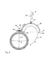
- an electromotive direct drive 50 also called “torque motor” is provided. It comprises a rotatably mounted on the outer circumference of the extension 10 arranged rotor 13, which comprises a permanent magnet assembly. Radially, the rotor 13 is surrounded by an annular gap 14 surrounded by a stator 15, which has a coil arrangement.
- a pivot bearing 16 is provided, via which the hollow cylinder 8 is supported directly on the axis 2.
- the axle 2 is in turn supported by a pendulum bearing 3 in a bearing device 4 ".
- the stator is in a plane E, which runs parallel to the axis of rotation D, formed in two parts, the two stator segments 17 thus obtained, of which in the Fig. 1 to 3
- a hinge part 18 which can be pushed onto a hinge pin 19.
- the hinge pin 19 of a hinge assembly 24 thus formed defines a hinge axis S, about which the stator segment 17 between a closed, the stator annularly merging position in which the plane E is approximately vertical (s. Fig. 1 ), and an open mounting position in which the plane E extends approximately horizontally, can be pivoted. In this position, the two second ends 22 of the stator segments 17 are spaced from each other.
- a separate hinge pin 19 is provided for each stator segment 17, a separate hinge pin 19 is provided. It is provided in the mounting position of the roller assembly almost vertically above the axis of rotation D, so that the stator segments 17 are pivoted solely by the weight of their mounting position to its closed position, as indicated by the arrows P in Fig. 3 is clarified. For pivoting the stator segments 17 between the closed operating position and the open mounting position then only a simple hoist is necessary, which may be formed for example by the cable 20 of a crane, not shown in the drawing.
- an eye 21 is provided approximately in the 90 ° position of the stator segment.
- the hinge pins 19 are in the in Fig. 1 to 4 illustrated embodiment firmly connected to the bearing bell 12. Since these in the two further, in the Fig. 5 and 6 is missing, it will be in these the hinge pin preferably directly to the storage facilities 4 ', 4 "attach.
- a disassembly of the roller assembly can accordingly be reversed.
Landscapes
- Engineering & Computer Science (AREA)
- Mechanical Engineering (AREA)
- Support Of The Bearing (AREA)
- Rolls And Other Rotary Bodies (AREA)
- Rolling Contact Bearings (AREA)
- Manufacture Of Motors, Generators (AREA)
- Connection Of Motors, Electrical Generators, Mechanical Devices, And The Like (AREA)
Claims (10)
- Agencement de cylindre (100),
comprenant un cylindre (1, 1') qui comprend un axe (2) ou un arbre (6) monté au niveau d'un point de palier (T),
comprenant un corps de cylindre (5, 5') formant la périphérie de travail du cylindre (1, 1'), lequel peut tourner autour d'un axe de rotation (D),
et comprenant un entraînement direct (50) par moteur électrique, dont le rotor (13) et dont le stator (15) sont disposés dans la direction de l'axe de rotation (D) entre le point de palier (T) et le corps de cylindre (5, 5'),
caractérisé en ce que
le stator (15) est divisé dans au moins un plan (E) parallèle ou oblique par rapport à l'axe de rotation (D) en segments de stator (17), et les segments de stator (17) sont supportés de manière pivotante par une première extrémité respective autour d'axes de charnière (S) s'étendant approximativement parallèlement à l'axe de rotation (D). - Agencement de cylindre selon la revendication 1, caractérisé en ce que les segments de stator (17) sont supportés de manière indirecte ou directe au niveau d'un dispositif de palier (4, 4', 4'').
- Agencement de cylindre selon la revendication 1 ou 2, caractérisé en ce que les axes de charnière (S) sont disposés de telle sorte que le poids agisse dans le sens d'un rapprochement des deuxièmes extrémités (22) tournées à l'écart des premières extrémités (23) de deux segments de stator adjacents (17).
- Agencement de cylindre selon la revendication 3, caractérisé en ce que le stator (15) comprend deux segments de stator (17), dont les premières extrémités (23) se trouvent approximativement verticalement au-dessus de l'axe de rotation (D) dans la position de montage de l'agencement de cylindre (100).
- Agencement de cylindre selon la revendication 4, caractérisé en ce qu'à chaque première extrémité des segments de stator (17) est prévue une partie d'un agencement de charnière (24) définissant un axe de charnière (S).
- Agencement de cylindre selon la revendication 5, caractérisé en ce que les axes de charnière (S) sont prévus avec des distances horizontales identiques en valeur absolue mais de signes opposés de la perpendiculaire (V) à l'axe de rotation (D).
- Agencement de cylindre selon l'une quelconque des revendications 1 à 6, caractérisé en ce que les axes de charnière (S) sont formés par des fiches de gond (19) qui coopèrent indirectement ou directement à chaque fois avec le dispositif de palier (4, 4', 4'') et avec l'un des segments de stator (17).
- Agencement de cylindre selon l'une quelconque des revendications 1 à 7, caractérisé en ce que les
segments de stator (17) comprennent des moyens pour appliquer un outil de levage (20), au moyen duquel les segments de stator (17) peuvent être pivotés entre une position ouverte et une position fermée autour des axes de charnière (S). - Agencement de cylindre selon l'une quelconque des revendications 1 à 8, caractérisé en ce que le cylindre est un cylindre commandé en flexion.
- Procédé de montage d'un agencement de cylindre (100) comprenant un entraînement direct (15) par moteur électrique avec un rotor (13) et un stator (15), qui comprend un cylindre (1, 1') pouvant tourner autour d'un axe de rotation (D), comprenant les étapes suivantes :- montage du rotor (13) sur une partie de l'agencement de cylindre (100) pouvant tourner autour de l'axe de rotation (D) du cylindre (1, 1') ;- disposition du support de palier de l'axe (2) du cylindre (1, 1') sur un dispositif de palier (4'') dans le cas d'un cylindre supporté à l'intérieur, disposition du support de palier du corps de cylindre (5) dans un dispositif de palier (4) dans le cas d'un cylindre supporté à l'extérieur ou disposition du support sur palier de l'arbre (6) du cylindre dans un dispositif de palier (4') dans le cas d'un cylindre conventionnel,- montage pivotant des segments de stator (17) d'un stator (15) divisé en au moins deux segments de stator (17) dans au moins un plan (E) s'étendant parallèlement ou obliquement par rapport à l'axe de rotation (D).
Applications Claiming Priority (2)
| Application Number | Priority Date | Filing Date | Title |
|---|---|---|---|
| DE102011001047A DE102011001047A1 (de) | 2011-03-03 | 2011-03-03 | Walzenanordnung mit elektromotorischem Direktantrieb und Montageverfahren |
| PCT/EP2012/051437 WO2012116865A2 (fr) | 2011-03-03 | 2012-01-30 | Ensemble de cylindres à entraînement direct électromoteur et procédé de montage |
Publications (2)
| Publication Number | Publication Date |
|---|---|
| EP2681360A2 EP2681360A2 (fr) | 2014-01-08 |
| EP2681360B1 true EP2681360B1 (fr) | 2014-11-05 |
Family
ID=45558071
Family Applications (1)
| Application Number | Title | Priority Date | Filing Date |
|---|---|---|---|
| EP12701751.5A Active EP2681360B1 (fr) | 2011-03-03 | 2012-01-30 | Ensemble de cylindres a entrainement direct electromoteur et procede de montage |
Country Status (4)
| Country | Link |
|---|---|
| EP (1) | EP2681360B1 (fr) |
| CN (1) | CN103354853B (fr) |
| DE (1) | DE102011001047A1 (fr) |
| WO (1) | WO2012116865A2 (fr) |
Families Citing this family (1)
| Publication number | Priority date | Publication date | Assignee | Title |
|---|---|---|---|---|
| ITUB20156031A1 (it) | 2015-11-30 | 2017-05-30 | Omas Srl | Laminatoio con motori a trascinamento diretto migliorato e metodo di funzionamento del laminatoio |
Family Cites Families (11)
| Publication number | Priority date | Publication date | Assignee | Title |
|---|---|---|---|---|
| FR2702202B1 (fr) * | 1993-03-05 | 1995-04-14 | Vesuvius France Sa | Rouleau monté tournant sur des paliers par une articulation à rotule. |
| DE29908433U1 (de) * | 1999-05-11 | 1999-07-29 | Voith Sulzer Papiertechnik Patent GmbH, 89522 Heidenheim | Walze |
| FI120104B (fi) * | 2000-05-05 | 2009-06-30 | Abb Research Ltd | Telakäyttö |
| AU2003229565A1 (en) * | 2002-03-24 | 2003-10-08 | Vomag Gmbh | Device for supporting a shaft |
| KR100839354B1 (ko) * | 2002-10-28 | 2008-06-19 | 도쿄파츠고교 가부시키가이샤 | 축방향 공극형 브러시리스 모터 |
| DE10319105A1 (de) * | 2003-04-28 | 2004-11-18 | Voith Paper Patent Gmbh | Drehteil mit Drehantrieb |
| DE10319012A1 (de) * | 2003-04-28 | 2004-11-18 | Voith Paper Patent Gmbh | Drehteil mit Hohlwellenmotor und konzentrisch dazu angeordneter Drehlagerung |
| DE10324664A1 (de) * | 2003-05-30 | 2004-12-30 | Siemens Ag | Rollen und Rollenmotoren |
| DE10339733A1 (de) | 2003-08-28 | 2004-11-25 | Siemens Ag | Antrieb zum rotatorischen Betrieb einer Walze |
| FI122849B (fi) * | 2009-11-10 | 2012-07-31 | Metso Paper Inc | Telakäyttö, tela ja menetelmä |
| DE102009059288B4 (de) * | 2009-12-23 | 2012-05-31 | Andritz Küsters Gmbh | Durchbiegesteuerbare Walze und Verfahren zum Antrieb derselben |
-
2011
- 2011-03-03 DE DE102011001047A patent/DE102011001047A1/de not_active Ceased
-
2012
- 2012-01-30 WO PCT/EP2012/051437 patent/WO2012116865A2/fr not_active Ceased
- 2012-01-30 EP EP12701751.5A patent/EP2681360B1/fr active Active
- 2012-01-30 CN CN201280008651.4A patent/CN103354853B/zh active Active
Also Published As
| Publication number | Publication date |
|---|---|
| EP2681360A2 (fr) | 2014-01-08 |
| DE102011001047A1 (de) | 2012-09-06 |
| WO2012116865A2 (fr) | 2012-09-07 |
| CN103354853A (zh) | 2013-10-16 |
| CN103354853B (zh) | 2015-06-24 |
| WO2012116865A3 (fr) | 2013-01-03 |
Similar Documents
| Publication | Publication Date | Title |
|---|---|---|
| EP1520076B1 (fr) | Fraiseuse de route automotrice | |
| EP2508749B1 (fr) | Procédé destiné au montage d'une machine électrique | |
| EP2562102B1 (fr) | Installation de transport à bande, son procédé de fonctionnement et d'utilisation | |
| EP2299560B1 (fr) | Procédé d'introduction d'un rotor d'une machine synchrone dans le stator ou pour l'agencement d'un rotor autour d'un stator et son dispositif de montage correspondant | |
| EP1668263B1 (fr) | Ensemble support rotatif d'un corps rotatif | |
| EP2088664B1 (fr) | Machine dotée d'un engrenage direct | |
| DE602005003946T2 (de) | Stützvorrichtung für prägewalzen und verfahren zu deren austausch | |
| DE3214257C2 (de) | Vorrichtung zum Nachführen eines Energiezuleitungs-Kabels | |
| DE102009015926A1 (de) | Gondel mit mehrteiliger Hauptwelle | |
| EP2610514B1 (fr) | Machine électrique | |
| EP3201440A1 (fr) | Turbine à gaz à dispositif de levage | |
| EP3308909B1 (fr) | Dispositif de manipulation | |
| EP2681360B1 (fr) | Ensemble de cylindres a entrainement direct electromoteur et procede de montage | |
| EP2678254B1 (fr) | Dispositif pour une courroie transporteuse avec un entraînement sans engrenage pour un tambour d' entraînement de la courroie transporteuse | |
| DE102019204673A1 (de) | Elektrischer Antrieb und Fahrzeug | |
| DE3106069A1 (de) | Zentriervorrichtung | |
| EP3843912B1 (fr) | Utilisation d'un dispositif de reglage d'un objet et laminoir | |
| EP3325379B1 (fr) | Entrainement pour une installation de transport a bande, procede de montage d'un entrainement sur une installation de transport a bande et transport a bande | |
| DE19539249A1 (de) | Fräse mit Abstützbuchse | |
| DE102009059288B4 (de) | Durchbiegesteuerbare Walze und Verfahren zum Antrieb derselben | |
| DE102011108647A1 (de) | Maschine zum Abtragen von Material am Umfang eines Schlauches | |
| DE102009049618A1 (de) | Rundschalttisch | |
| DE4037259A1 (de) | Zielbohrstange mit eigener elektrischer energieversorgung durch einen eingebauten generator | |
| EP2610187A1 (fr) | Dispositif de transfert de pièces d'équipement pour l'étiquetage de récipients | |
| WO2012059535A1 (fr) | Palier à roulement à entraînement direct |
Legal Events
| Date | Code | Title | Description |
|---|---|---|---|
| PUAI | Public reference made under article 153(3) epc to a published international application that has entered the european phase |
Free format text: ORIGINAL CODE: 0009012 |
|
| 17P | Request for examination filed |
Effective date: 20130918 |
|
| AK | Designated contracting states |
Kind code of ref document: A2 Designated state(s): AL AT BE BG CH CY CZ DE DK EE ES FI FR GB GR HR HU IE IS IT LI LT LU LV MC MK MT NL NO PL PT RO RS SE SI SK SM TR |
|
| DAX | Request for extension of the european patent (deleted) | ||
| GRAP | Despatch of communication of intention to grant a patent |
Free format text: ORIGINAL CODE: EPIDOSNIGR1 |
|
| INTG | Intention to grant announced |
Effective date: 20140620 |
|
| GRAS | Grant fee paid |
Free format text: ORIGINAL CODE: EPIDOSNIGR3 |
|
| GRAP | Despatch of communication of intention to grant a patent |
Free format text: ORIGINAL CODE: EPIDOSNIGR1 |
|
| GRAA | (expected) grant |
Free format text: ORIGINAL CODE: 0009210 |
|
| INTG | Intention to grant announced |
Effective date: 20140922 |
|
| AK | Designated contracting states |
Kind code of ref document: B1 Designated state(s): AL AT BE BG CH CY CZ DE DK EE ES FI FR GB GR HR HU IE IS IT LI LT LU LV MC MK MT NL NO PL PT RO RS SE SI SK SM TR |
|
| REG | Reference to a national code |
Ref country code: GB Ref legal event code: FG4D Free format text: NOT ENGLISH |
|
| REG | Reference to a national code |
Ref country code: CH Ref legal event code: EP |
|
| REG | Reference to a national code |
Ref country code: AT Ref legal event code: REF Ref document number: 694742 Country of ref document: AT Kind code of ref document: T Effective date: 20141115 |
|
| REG | Reference to a national code |
Ref country code: IE Ref legal event code: FG4D Free format text: LANGUAGE OF EP DOCUMENT: GERMAN |
|
| REG | Reference to a national code |
Ref country code: DE Ref legal event code: R096 Ref document number: 502012001539 Country of ref document: DE Effective date: 20141218 |
|
| REG | Reference to a national code |
Ref country code: NL Ref legal event code: VDEP Effective date: 20141105 |
|
| REG | Reference to a national code |
Ref country code: LT Ref legal event code: MG4D |
|
| PG25 | Lapsed in a contracting state [announced via postgrant information from national office to epo] |
Ref country code: IS Free format text: LAPSE BECAUSE OF FAILURE TO SUBMIT A TRANSLATION OF THE DESCRIPTION OR TO PAY THE FEE WITHIN THE PRESCRIBED TIME-LIMIT Effective date: 20150305 Ref country code: LT Free format text: LAPSE BECAUSE OF FAILURE TO SUBMIT A TRANSLATION OF THE DESCRIPTION OR TO PAY THE FEE WITHIN THE PRESCRIBED TIME-LIMIT Effective date: 20141105 Ref country code: PT Free format text: LAPSE BECAUSE OF FAILURE TO SUBMIT A TRANSLATION OF THE DESCRIPTION OR TO PAY THE FEE WITHIN THE PRESCRIBED TIME-LIMIT Effective date: 20150305 Ref country code: ES Free format text: LAPSE BECAUSE OF FAILURE TO SUBMIT A TRANSLATION OF THE DESCRIPTION OR TO PAY THE FEE WITHIN THE PRESCRIBED TIME-LIMIT Effective date: 20141105 Ref country code: NO Free format text: LAPSE BECAUSE OF FAILURE TO SUBMIT A TRANSLATION OF THE DESCRIPTION OR TO PAY THE FEE WITHIN THE PRESCRIBED TIME-LIMIT Effective date: 20150205 Ref country code: FI Free format text: LAPSE BECAUSE OF FAILURE TO SUBMIT A TRANSLATION OF THE DESCRIPTION OR TO PAY THE FEE WITHIN THE PRESCRIBED TIME-LIMIT Effective date: 20141105 Ref country code: NL Free format text: LAPSE BECAUSE OF FAILURE TO SUBMIT A TRANSLATION OF THE DESCRIPTION OR TO PAY THE FEE WITHIN THE PRESCRIBED TIME-LIMIT Effective date: 20141105 |
|
| PG25 | Lapsed in a contracting state [announced via postgrant information from national office to epo] |
Ref country code: PL Free format text: LAPSE BECAUSE OF FAILURE TO SUBMIT A TRANSLATION OF THE DESCRIPTION OR TO PAY THE FEE WITHIN THE PRESCRIBED TIME-LIMIT Effective date: 20141105 Ref country code: SE Free format text: LAPSE BECAUSE OF FAILURE TO SUBMIT A TRANSLATION OF THE DESCRIPTION OR TO PAY THE FEE WITHIN THE PRESCRIBED TIME-LIMIT Effective date: 20141105 Ref country code: HR Free format text: LAPSE BECAUSE OF FAILURE TO SUBMIT A TRANSLATION OF THE DESCRIPTION OR TO PAY THE FEE WITHIN THE PRESCRIBED TIME-LIMIT Effective date: 20141105 Ref country code: CY Free format text: LAPSE BECAUSE OF FAILURE TO SUBMIT A TRANSLATION OF THE DESCRIPTION OR TO PAY THE FEE WITHIN THE PRESCRIBED TIME-LIMIT Effective date: 20141105 Ref country code: RS Free format text: LAPSE BECAUSE OF FAILURE TO SUBMIT A TRANSLATION OF THE DESCRIPTION OR TO PAY THE FEE WITHIN THE PRESCRIBED TIME-LIMIT Effective date: 20141105 Ref country code: LV Free format text: LAPSE BECAUSE OF FAILURE TO SUBMIT A TRANSLATION OF THE DESCRIPTION OR TO PAY THE FEE WITHIN THE PRESCRIBED TIME-LIMIT Effective date: 20141105 Ref country code: GR Free format text: LAPSE BECAUSE OF FAILURE TO SUBMIT A TRANSLATION OF THE DESCRIPTION OR TO PAY THE FEE WITHIN THE PRESCRIBED TIME-LIMIT Effective date: 20150206 |
|
| PG25 | Lapsed in a contracting state [announced via postgrant information from national office to epo] |
Ref country code: SK Free format text: LAPSE BECAUSE OF FAILURE TO SUBMIT A TRANSLATION OF THE DESCRIPTION OR TO PAY THE FEE WITHIN THE PRESCRIBED TIME-LIMIT Effective date: 20141105 Ref country code: CZ Free format text: LAPSE BECAUSE OF FAILURE TO SUBMIT A TRANSLATION OF THE DESCRIPTION OR TO PAY THE FEE WITHIN THE PRESCRIBED TIME-LIMIT Effective date: 20141105 Ref country code: DK Free format text: LAPSE BECAUSE OF FAILURE TO SUBMIT A TRANSLATION OF THE DESCRIPTION OR TO PAY THE FEE WITHIN THE PRESCRIBED TIME-LIMIT Effective date: 20141105 Ref country code: EE Free format text: LAPSE BECAUSE OF FAILURE TO SUBMIT A TRANSLATION OF THE DESCRIPTION OR TO PAY THE FEE WITHIN THE PRESCRIBED TIME-LIMIT Effective date: 20141105 |
|
| REG | Reference to a national code |
Ref country code: DE Ref legal event code: R097 Ref document number: 502012001539 Country of ref document: DE |
|
| REG | Reference to a national code |
Ref country code: CH Ref legal event code: PL |
|
| PG25 | Lapsed in a contracting state [announced via postgrant information from national office to epo] |
Ref country code: LU Free format text: LAPSE BECAUSE OF FAILURE TO SUBMIT A TRANSLATION OF THE DESCRIPTION OR TO PAY THE FEE WITHIN THE PRESCRIBED TIME-LIMIT Effective date: 20150130 |
|
| PLBE | No opposition filed within time limit |
Free format text: ORIGINAL CODE: 0009261 |
|
| STAA | Information on the status of an ep patent application or granted ep patent |
Free format text: STATUS: NO OPPOSITION FILED WITHIN TIME LIMIT |
|
| PG25 | Lapsed in a contracting state [announced via postgrant information from national office to epo] |
Ref country code: MC Free format text: LAPSE BECAUSE OF FAILURE TO SUBMIT A TRANSLATION OF THE DESCRIPTION OR TO PAY THE FEE WITHIN THE PRESCRIBED TIME-LIMIT Effective date: 20141105 |
|
| 26N | No opposition filed |
Effective date: 20150806 |
|
| PG25 | Lapsed in a contracting state [announced via postgrant information from national office to epo] |
Ref country code: CH Free format text: LAPSE BECAUSE OF NON-PAYMENT OF DUE FEES Effective date: 20150131 Ref country code: LI Free format text: LAPSE BECAUSE OF NON-PAYMENT OF DUE FEES Effective date: 20150131 |
|
| REG | Reference to a national code |
Ref country code: FR Ref legal event code: ST Effective date: 20150930 |
|
| REG | Reference to a national code |
Ref country code: IE Ref legal event code: MM4A |
|
| PG25 | Lapsed in a contracting state [announced via postgrant information from national office to epo] |
Ref country code: FR Free format text: LAPSE BECAUSE OF NON-PAYMENT OF DUE FEES Effective date: 20150202 |
|
| PG25 | Lapsed in a contracting state [announced via postgrant information from national office to epo] |
Ref country code: IE Free format text: LAPSE BECAUSE OF NON-PAYMENT OF DUE FEES Effective date: 20150130 |
|
| PG25 | Lapsed in a contracting state [announced via postgrant information from national office to epo] |
Ref country code: SI Free format text: LAPSE BECAUSE OF FAILURE TO SUBMIT A TRANSLATION OF THE DESCRIPTION OR TO PAY THE FEE WITHIN THE PRESCRIBED TIME-LIMIT Effective date: 20141105 |
|
| PG25 | Lapsed in a contracting state [announced via postgrant information from national office to epo] |
Ref country code: RO Free format text: LAPSE BECAUSE OF FAILURE TO SUBMIT A TRANSLATION OF THE DESCRIPTION OR TO PAY THE FEE WITHIN THE PRESCRIBED TIME-LIMIT Effective date: 20141105 |
|
| GBPC | Gb: european patent ceased through non-payment of renewal fee |
Effective date: 20160130 |
|
| PG25 | Lapsed in a contracting state [announced via postgrant information from national office to epo] |
Ref country code: GB Free format text: LAPSE BECAUSE OF NON-PAYMENT OF DUE FEES Effective date: 20160130 |
|
| PG25 | Lapsed in a contracting state [announced via postgrant information from national office to epo] |
Ref country code: MT Free format text: LAPSE BECAUSE OF FAILURE TO SUBMIT A TRANSLATION OF THE DESCRIPTION OR TO PAY THE FEE WITHIN THE PRESCRIBED TIME-LIMIT Effective date: 20141105 |
|
| PG25 | Lapsed in a contracting state [announced via postgrant information from national office to epo] |
Ref country code: BG Free format text: LAPSE BECAUSE OF FAILURE TO SUBMIT A TRANSLATION OF THE DESCRIPTION OR TO PAY THE FEE WITHIN THE PRESCRIBED TIME-LIMIT Effective date: 20141105 Ref country code: HU Free format text: LAPSE BECAUSE OF FAILURE TO SUBMIT A TRANSLATION OF THE DESCRIPTION OR TO PAY THE FEE WITHIN THE PRESCRIBED TIME-LIMIT; INVALID AB INITIO Effective date: 20120130 Ref country code: SM Free format text: LAPSE BECAUSE OF FAILURE TO SUBMIT A TRANSLATION OF THE DESCRIPTION OR TO PAY THE FEE WITHIN THE PRESCRIBED TIME-LIMIT Effective date: 20141105 |
|
| PG25 | Lapsed in a contracting state [announced via postgrant information from national office to epo] |
Ref country code: BE Free format text: LAPSE BECAUSE OF NON-PAYMENT OF DUE FEES Effective date: 20150131 |
|
| PG25 | Lapsed in a contracting state [announced via postgrant information from national office to epo] |
Ref country code: TR Free format text: LAPSE BECAUSE OF FAILURE TO SUBMIT A TRANSLATION OF THE DESCRIPTION OR TO PAY THE FEE WITHIN THE PRESCRIBED TIME-LIMIT Effective date: 20141105 |
|
| REG | Reference to a national code |
Ref country code: AT Ref legal event code: MM01 Ref document number: 694742 Country of ref document: AT Kind code of ref document: T Effective date: 20170130 |
|
| PG25 | Lapsed in a contracting state [announced via postgrant information from national office to epo] |
Ref country code: AT Free format text: LAPSE BECAUSE OF NON-PAYMENT OF DUE FEES Effective date: 20170130 |
|
| PG25 | Lapsed in a contracting state [announced via postgrant information from national office to epo] |
Ref country code: MK Free format text: LAPSE BECAUSE OF FAILURE TO SUBMIT A TRANSLATION OF THE DESCRIPTION OR TO PAY THE FEE WITHIN THE PRESCRIBED TIME-LIMIT Effective date: 20141105 |
|
| PG25 | Lapsed in a contracting state [announced via postgrant information from national office to epo] |
Ref country code: AL Free format text: LAPSE BECAUSE OF FAILURE TO SUBMIT A TRANSLATION OF THE DESCRIPTION OR TO PAY THE FEE WITHIN THE PRESCRIBED TIME-LIMIT Effective date: 20141105 |
|
| REG | Reference to a national code |
Ref country code: DE Ref legal event code: R082 Ref document number: 502012001539 Country of ref document: DE Representative=s name: PATENTANWAELTE KLUIN DEBELIUS WEBER PARTG MBB, DE |
|
| P01 | Opt-out of the competence of the unified patent court (upc) registered |
Effective date: 20230524 |
|
| PGFP | Annual fee paid to national office [announced via postgrant information from national office to epo] |
Ref country code: IT Payment date: 20250131 Year of fee payment: 14 |
|
| PGFP | Annual fee paid to national office [announced via postgrant information from national office to epo] |
Ref country code: DE Payment date: 20260131 Year of fee payment: 15 |