EP2681434B1 - Verfahren zum bestimmen einer eigenschaft eines kraftstoffs - Google Patents
Verfahren zum bestimmen einer eigenschaft eines kraftstoffs Download PDFInfo
- Publication number
- EP2681434B1 EP2681434B1 EP12703067.4A EP12703067A EP2681434B1 EP 2681434 B1 EP2681434 B1 EP 2681434B1 EP 12703067 A EP12703067 A EP 12703067A EP 2681434 B1 EP2681434 B1 EP 2681434B1
- Authority
- EP
- European Patent Office
- Prior art keywords
- fuel
- property
- viscosity
- internal combustion
- combustion engine
- Prior art date
- Legal status (The legal status is an assumption and is not a legal conclusion. Google has not performed a legal analysis and makes no representation as to the accuracy of the status listed.)
- Active
Links
Images



Classifications
-
- F—MECHANICAL ENGINEERING; LIGHTING; HEATING; WEAPONS; BLASTING
- F02—COMBUSTION ENGINES; HOT-GAS OR COMBUSTION-PRODUCT ENGINE PLANTS
- F02D—CONTROLLING COMBUSTION ENGINES
- F02D41/00—Electrical control of supply of combustible mixture or its constituents
- F02D41/30—Controlling fuel injection
- F02D41/38—Controlling fuel injection of the high pressure type
- F02D41/40—Controlling fuel injection of the high pressure type with means for controlling injection timing or duration
- F02D41/401—Controlling injection timing
-
- F—MECHANICAL ENGINEERING; LIGHTING; HEATING; WEAPONS; BLASTING
- F02—COMBUSTION ENGINES; HOT-GAS OR COMBUSTION-PRODUCT ENGINE PLANTS
- F02M—SUPPLYING COMBUSTION ENGINES IN GENERAL WITH COMBUSTIBLE MIXTURES OR CONSTITUENTS THEREOF
- F02M65/00—Testing fuel-injection apparatus, e.g. testing injection timing ; Cleaning of fuel-injection apparatus
-
- F—MECHANICAL ENGINEERING; LIGHTING; HEATING; WEAPONS; BLASTING
- F02—COMBUSTION ENGINES; HOT-GAS OR COMBUSTION-PRODUCT ENGINE PLANTS
- F02D—CONTROLLING COMBUSTION ENGINES
- F02D41/00—Electrical control of supply of combustible mixture or its constituents
- F02D41/30—Controlling fuel injection
- F02D41/38—Controlling fuel injection of the high pressure type
- F02D41/40—Controlling fuel injection of the high pressure type with means for controlling injection timing or duration
-
- F—MECHANICAL ENGINEERING; LIGHTING; HEATING; WEAPONS; BLASTING
- F02—COMBUSTION ENGINES; HOT-GAS OR COMBUSTION-PRODUCT ENGINE PLANTS
- F02M—SUPPLYING COMBUSTION ENGINES IN GENERAL WITH COMBUSTIBLE MIXTURES OR CONSTITUENTS THEREOF
- F02M65/00—Testing fuel-injection apparatus, e.g. testing injection timing ; Cleaning of fuel-injection apparatus
- F02M65/005—Measuring or detecting injection-valve lift, e.g. to determine injection timing
-
- G—PHYSICS
- G01—MEASURING; TESTING
- G01N—INVESTIGATING OR ANALYSING MATERIALS BY DETERMINING THEIR CHEMICAL OR PHYSICAL PROPERTIES
- G01N33/00—Investigating or analysing materials by specific methods not covered by groups G01N1/00 - G01N31/00
- G01N33/26—Oils; Viscous liquids; Paints; Inks
- G01N33/28—Oils, i.e. hydrocarbon liquids
-
- F—MECHANICAL ENGINEERING; LIGHTING; HEATING; WEAPONS; BLASTING
- F02—COMBUSTION ENGINES; HOT-GAS OR COMBUSTION-PRODUCT ENGINE PLANTS
- F02D—CONTROLLING COMBUSTION ENGINES
- F02D19/00—Controlling engines characterised by their use of non-liquid fuels, pluralities of fuels, or non-fuel substances added to the combustible mixtures
- F02D19/06—Controlling engines characterised by their use of non-liquid fuels, pluralities of fuels, or non-fuel substances added to the combustible mixtures peculiar to engines working with pluralities of fuels, e.g. alternatively with light and heavy fuel oil, other than engines indifferent to the fuel consumed
- F02D19/0626—Measuring or estimating parameters related to the fuel supply system
- F02D19/0634—Determining a density, viscosity, composition or concentration
- F02D19/0636—Determining a density, viscosity, composition or concentration by estimation, i.e. without using direct measurements of a corresponding sensor
-
- F—MECHANICAL ENGINEERING; LIGHTING; HEATING; WEAPONS; BLASTING
- F02—COMBUSTION ENGINES; HOT-GAS OR COMBUSTION-PRODUCT ENGINE PLANTS
- F02D—CONTROLLING COMBUSTION ENGINES
- F02D2200/00—Input parameters for engine control
- F02D2200/02—Input parameters for engine control the parameters being related to the engine
- F02D2200/06—Fuel or fuel supply system parameters
- F02D2200/0611—Fuel type, fuel composition or fuel quality
- F02D2200/0612—Fuel type, fuel composition or fuel quality determined by estimation
-
- F—MECHANICAL ENGINEERING; LIGHTING; HEATING; WEAPONS; BLASTING
- F02—COMBUSTION ENGINES; HOT-GAS OR COMBUSTION-PRODUCT ENGINE PLANTS
- F02D—CONTROLLING COMBUSTION ENGINES
- F02D2200/00—Input parameters for engine control
- F02D2200/02—Input parameters for engine control the parameters being related to the engine
- F02D2200/06—Fuel or fuel supply system parameters
- F02D2200/063—Lift of the valve needle
-
- Y—GENERAL TAGGING OF NEW TECHNOLOGICAL DEVELOPMENTS; GENERAL TAGGING OF CROSS-SECTIONAL TECHNOLOGIES SPANNING OVER SEVERAL SECTIONS OF THE IPC; TECHNICAL SUBJECTS COVERED BY FORMER USPC CROSS-REFERENCE ART COLLECTIONS [XRACs] AND DIGESTS
- Y02—TECHNOLOGIES OR APPLICATIONS FOR MITIGATION OR ADAPTATION AGAINST CLIMATE CHANGE
- Y02T—CLIMATE CHANGE MITIGATION TECHNOLOGIES RELATED TO TRANSPORTATION
- Y02T10/00—Road transport of goods or passengers
- Y02T10/10—Internal combustion engine [ICE] based vehicles
- Y02T10/30—Use of alternative fuels, e.g. biofuels
-
- Y—GENERAL TAGGING OF NEW TECHNOLOGICAL DEVELOPMENTS; GENERAL TAGGING OF CROSS-SECTIONAL TECHNOLOGIES SPANNING OVER SEVERAL SECTIONS OF THE IPC; TECHNICAL SUBJECTS COVERED BY FORMER USPC CROSS-REFERENCE ART COLLECTIONS [XRACs] AND DIGESTS
- Y02—TECHNOLOGIES OR APPLICATIONS FOR MITIGATION OR ADAPTATION AGAINST CLIMATE CHANGE
- Y02T—CLIMATE CHANGE MITIGATION TECHNOLOGIES RELATED TO TRANSPORTATION
- Y02T10/00—Road transport of goods or passengers
- Y02T10/10—Internal combustion engine [ICE] based vehicles
- Y02T10/40—Engine management systems
Definitions
- the invention relates to a method for determining at least one property of a fuel, a method for operating an internal combustion engine and an arrangement for carrying out the method.
- CRS Common Rail Systems
- start time requirements vary at a minimum temperature. It is desirable to have a start time, i. H. a time interval until the end of the starting state, even at a cold start to shorten.
- the DE 102 52 476 A1 shows a method for determining the fuel type.
- a solenoid valve is actuated and determines the time of the local minimum of the current. This local minimum marks the opening time of the solenoid valve. Based on the comparison with a stored time, the fuel type is determined.
- a device for determining properties of a fuel of a diesel engine is known from the document DE 196 44 102 A1 known. It is provided that, in particular, its viscosity is determined as a property of the fuel.
- a starting time for a fuel supply of a pump piston to an injection nozzle and a start time of the fuel injection of the injection nozzle are sampled.
- a difference between the fuel supply start timing and the fuel injection starting timing is calculated and regarded as an injection delay period.
- An injection timing control for diesel engine fuel is from the document DE 43 23 967 A1 known.
- a control pressure of a fuel to be injected is adjusted by a control valve according to its opening.
- a viscosity of the fuel used is calculated from a duty ratio of a pulse signal supplied to the control valve.
- a method for operating a hydraulically actuated fuel injection system is in the document US 5,357,912 described.
- a map and / or equations are used to control an injection nozzle. From the map and / or the equations, the transport properties are determined as a function of a pressure and a viscosity of the fuel.
- the method is used in a solenoid valve, in particular in a solenoid valve of a common rail actuator, with the method, for example, an optimization can be achieved at cold start. Furthermore, components of the entire system can be protected.
- the solenoid valve which is in the fuel, has a magnetic armature that moves through the fuel.
- the viscosity of the fuel has an effect on the dynamic behavior of the magnet armature. This is a relationship between the closing time of the armature and the viscosity of the fuel.
- the closing duration can be measured for one control period or for several activation periods. If, for example, two measurements are carried out, the determined difference between the two activation periods can be further processed and evaluated by means of mathematical methods.
- fuel properties are determined, such as the viscosity. From this, specific correction values for the activation duration can be determined.
- the aim is to equalize the injection quantity regardless of the fuel properties, such. the viscosity.
- the measurements are based on the function VCA / VCC (valve close adaptation / valve close control).
- VCA valve close adaptation / valve close control
- the closing duration of the magnet armature is determined by means of a sensor current. This method is described with reference to FIG. 5 described.
- the closing time of the armature is defined as the time from the beginning of the current extinction of the magnet to the impact of the armature in the valve seat.
- the time of impact is determined by the fact that, after the current in the coil reaches zero and after a defined period, which may be, for example.
- the solenoid valve coil is energized with a sensor current.
- the sensor current undergoes a change due to the inductance change triggered by the movement of the armature in the magnetic field. This change in the sensor current can be clearly measured in the event of a significant change in the speed, for example due to the impact of the armature in the seat.
- the time required for the armature to close that is, the closing time, can be determined.
- a factor or a variable can then be determined which represents the at least one property, in particular the viscosity, of the fuel.
- Fuel properties include, in addition to viscosity, a composition of the fuel, i. H. a content of different fuel components and thus a kind of fuel, and flow properties, which result from the composition of the fuel as well as dependent on environmental influences, such as the temperature. If the fuel properties are known, it is possible to adapt an operation of the internal combustion engine to the fuel properties and thus the composition of the fuel, taking into account the environmental influences.
- the quantity inaccuracy with variation of fuel properties can be reduced without having to integrate additional sensors in the injection system.
- the method for operating an internal combustion engine uses the method described above, wherein at least one operating parameter of an injection system comprising a solenoid valve of the internal combustion engine is set as a function of the determined property, in particular the viscosity of the fuel.
- the arrangement according to the invention is designed to carry out all the steps of the presented method for determining at least one property of a fuel.
- individual steps of this method can also be carried out by individual components of the arrangement.
- functions of the arrangement or functions of individual components of the arrangement may be implemented as steps of the method for determining at least one property.
- steps of the method may be realized as functions of at least one component of the arrangement or of the entire arrangement.
- the property of the fuel determined by the method for determining the at least one property and by the arrangement may further be used for the method for operating the internal combustion engine.
- FIG. 1 is an abscissa 20 a drive time in ⁇ s and along an ordinate 22 an injection amount for a fuel in mm 3 plotted.
- the curves 24, 26 shown were determined from the average values of several cold cell tests at a rail pressure of 600 bar and thus a pressure of the named types of fuel in a fuel tank of an injection system in this case at -25 ° C.
- FIG. 2 10 shows a diagram 102 with an abscissa 104, along which a temperature in ° C. is plotted, and an ordinate 106, along which a kinematic viscosity of a fuel in mm 2 / s is plotted.
- the diagram comprises four curves 108, 110, 112, 114.
- a first curve 108 represents a temperature-dependent kinematic viscosity of a first winter diesel fuel
- a second curve 110 a temperature-dependent kinematic viscosity of a test diesel
- a third curve 112 a temperature-dependent kinematic viscosity of a winter diesel fuel
- a fourth curve 114 is a temperature-dependent kinematic viscosity of a so-called Arctic diesel fuel.
- the graph 102 of FIG. 1 shows a temperature dependence of kinematic viscosities for various types of winter diesel.
- FIG. 3 10 shows a graph 184 with an abscissa 186, along which a dynamic viscosity in mm 2 / s is plotted, and an ordinate 188, along which a closing duration difference in ⁇ s is plotted.
- this graph 184 are multiple squares for closure duration differences, which are a function of kinematic viscosities from measurements with different fuels at different temperatures, shown.
- a curve 190 represents a correlation of the measured values.
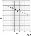
- FIG. 4 shows the relationship between injection quantity and viscosity.
- the viscosity in mm 2 / s and at an ordinate 202, the injection quantity in mm 3 / stroke is plotted on an abscissa 200.
- FIG. 5 is a typical course of a sensor current shown to illustrate how, for example, the closing time of the armature can be measured.
- the sensor current versus time (abscissa 252) is plotted on an ordinate 250.
- the accuracy of the set sensor current in the case of boosting depends on the accuracy of the booster voltage and on the accuracy with which the control unit terminates the switching state "boosting" when a switch-off threshold is reached.
- a renewed increase in the magnetic force of the valve which leads to a slight delay in the closing operation of the solenoid valve.
- the illustration shows in a first area 254 a quick-clear, in which the measuring range of the voltage is exceeded.
- a renewed booster in a second area 256 serves to build up the sensor current, wherein the measuring range of the voltage is exceeded.
- a kink in the course of the current can be seen, which indicates the closing time.
- FIG. 6 shows a schematic representation of an arrangement 300 for determining at least one property, in particular the viscosity, of a fuel.
- This arrangement comprises a control unit 302 with evaluation electronics for carrying out the calculation methods required for the methods described above.
- the assembly 300 is connected via electrical connections 304 to an injection system 305, which comprises a solenoid valve 306, as a valve unit of an internal combustion engine Coupled 308.
- This solenoid valve 306 includes an armature 310 that is moved to close and open the solenoid valve 306.
- the illustration shows a fuel feed line 312 through which fuel 314 is supplied to the solenoid valve 306.
- the armature 310 moves when opening and closing by this fuel 314, properties of the fuel, in particular its viscosity, thereby influencing the dynamic behavior of the armature 310. It is now the closing time measured and determined on the basis of the measured closing period, a factor that the at least represents a property, such as the viscosity, of the fuel.
Landscapes
- Engineering & Computer Science (AREA)
- Chemical & Material Sciences (AREA)
- Combustion & Propulsion (AREA)
- Mechanical Engineering (AREA)
- General Engineering & Computer Science (AREA)
- Health & Medical Sciences (AREA)
- Life Sciences & Earth Sciences (AREA)
- Food Science & Technology (AREA)
- Biochemistry (AREA)
- General Chemical & Material Sciences (AREA)
- Chemical Kinetics & Catalysis (AREA)
- Medicinal Chemistry (AREA)
- Physics & Mathematics (AREA)
- Analytical Chemistry (AREA)
- Oil, Petroleum & Natural Gas (AREA)
- General Health & Medical Sciences (AREA)
- General Physics & Mathematics (AREA)
- Immunology (AREA)
- Pathology (AREA)
- Electrical Control Of Air Or Fuel Supplied To Internal-Combustion Engine (AREA)
- Combined Controls Of Internal Combustion Engines (AREA)
- Feeding And Controlling Fuel (AREA)
- Fuel-Injection Apparatus (AREA)
Description
- Die Erfindung betrifft ein Verfahren zum Bestimmen mindestens einer Eigenschaft eines Kraftstoffs, ein Verfahren zum Betreiben eines Verbrennungsmotors und eine Anordnung zur Durchführung der Verfahren.
- Die Einspritzmenge bei Common Rail Systemen (CRS) ist unter anderem von verschiedenen Kraftstoffeigenschaften abhängig, die wiederum von der Art des Kraftstoffs und den Umgebungsbedingungen abhängen. Beispielsweise ist die Viskosität der Kraftstoffsorte, bspw. Winterdiesel, Arcticdiesel, Biodiesel, Mischungen verschiedener Kraftstoffsorten, und zusätzlich auch von der Temperatur abhängig. Solange im CRS keine Möglichkeit besteht, wichtige Kraftstoffeigenschaften, z. B. über einen Sensor, zu bestimmen, können Mengeneinflüsse dieser Eigenschaften nur ungenügend oder überhaupt nicht korrigiert werden.
- Es ist zu beachten, dass für einen unterhalb des Gefrierpunkts durchzuführenden Kaltstart üblicherweise größere Startzeiten als bei einem Start oberhalb des Gefrierpunkts zulässig sind. Hierbei variieren die Anforderungen bezüglich der Startzeit bei einer minimalen Temperatur. Es wird angestrebt, eine Startzeit, d. h. ein Zeitintervall bis zum Ende des Startzustands, auch bei einem Kaltstart zu verkürzen.
- Die
DE 102 52 476 A1 zeigt ein Verfahren zur Bestimmung der Kraftstoffart. Während des Betriebes der Brennkraftmaschine wird ein Magnetventil betätigt und der Zeitpunkt des lokalen Minimums des Stroms bestimmt. Diese lokale Minimum kennzeichnet, den Öffnungszeitpunkt des Magnetventils. Ausgehend von dem Vergleich mit einem gespeicherten Zeitpunkt wird die Kraftstoffart bestimmt. - Eine Vorrichtung zur Bestimmung von Eigenschaften eines Brennstoffs einer Dieselmaschine ist aus der Druckschrift
DE 196 44 102 A1 bekannt. Hierbei ist vorgesehen, dass als Eigenschaft des Brennstoffs insbesondere dessen Viskosität bestimmt wird. Hierbei werden ein Startzeitpunkt für eine Brennstoffzufuhr eines Pumpenkolbens an eine Einspritzdüse und ein Startzeitpunkt der Brennstoffeinspritzung der Einspritzdüse abgetastet. Eine Differenz zwischen dem Startzeitpunkt für die Brennstoffzufuhr und dem Startzeitpunkt für die Brennstoffeinspritzung wird berechnet und als Einspritzverzögerungsperiode betrachtet. - Eine Einspritztaktsteuerung für Dieselmotorbrennstoff ist aus der Druckschrift
DE 43 23 967 A1 bekannt. Dabei wird ein Steuerdruck eines einzuspritzenden Brennstoffs durch ein Steuerventil entsprechend seiner Öffnung eingestellt. Eine Viskosität des verwendeten Brennstoffs wird aus einem Einschaltverhältnis eines Impulssignals, das dem Steuerventil zugeführt wird, berechnet. - Ein Verfahren zum Betreiben eines hydraulisch beaufschlagten Kraftstoffeinspritzsystems ist in der Druckschrift
US 5 357 912 beschrieben. Hierbei werden ein Kennfeld und/oder Gleichungen zur Kontrolle einer Einspritzdüse verwendet. Aus dem Kennfeld und/oder den Gleichungen werden die Transporteigenschaften in Abhängigkeit eines Drucks sowie einer Viskosität des Kraftstoffs bestimmt. - Vor diesem Hintergrund werden ein Verfahren zum Bestimmen mindestens einer Eigenschaft eines Kraftstoffs, ein Verfahren zum Betreiben eines Verbrennungsmotors und eine Anordnung mit den Merkmalen der unabhängigen Patentansprüche vorgestellt. Weitere Ausgestaltungen der Erfindung ergeben sich aus den abhängigen Patentansprüchen und der Beschreibung.
- Es wird somit ein Verfahren vorgestellt, das mit Hilfe vorhandener Komponenten, d.h. ohne dass ein zusätzlicher Sensor erforderlich ist, Kraftstoffeigenschaften, wie insbesondere die Viskosität, bestimmt. Diese Kraftstoffeigenschaften beeinflussen das dynamische Verhalten des durch den Kraftstoff bewegten Ankers und damit auch die Schließdauer.
- Das Verfahren wird bei einem Magnetventil, insbesondere bei einem Magnetventil eines Common-Rail-Aktors, eingesetzt, wobei mit dem Verfahren z.B. eine Optimierung bei Kaltstart erreicht werden kann. Weiterhin können Komponenten der gesamten Anlage geschützt werden.
- Das Magnetventil, das sich im Kraftstoff befindet, weist einen Magnetanker auf, der sich durch den Kraftstoff bewegt. Die Viskosität des Kraftstoffs wirkt sich dabei auf das dynamische Verhalten des Magnetankers aus. Damit besteht ein Zusammenhang zwischen Schließdauer des Magnetankers und der Viskosität des Kraftstoffs.
- Die Schließdauer kann bei einer Ansteuerdauer oder bei mehreren Ansteuerdauern gemessen werden. Werden bspw. zwei Messungen durchgeführt, kann die ermittelte Differenz zwischen den beiden Ansteuerdauern mittels mathematischer Methoden weiterverarbeitet und ausgewertet werden.
- Auf diese Weise werden Kraftstoffeigenschaften bestimmt, wie bspw. die Viskosität. Daraus können spezifische Korrekturwerte für die Ansteuerdauer ermittelt werden. Ziel ist dabei die Gleichstellung der Einspritzmenge unabhängig von den Kraftstoffeigenschaften, wie z.B. der Viskosität.
- Die Messungen basieren auf der Funktion VCA/VCC (valve close adaption/valve close control). Dabei wird mittels eines Sensorstroms die Schließdauer des Magnetankers bestimmt. Dieses Verfahren wird unter Bezugnahme auf
Figur 5 beschrieben. - Die Schließdauer des Magnetankers ist definiert als die Zeit von Beginn der Stromlöschung des Magnets bis zum Einschlag des Magnetankers im Ventilsitz. Der Zeitpunkt des Einschlags wird dadurch bestimmt, dass, nachdem der Strom in der Spule den Wert Null erreicht und nach einem definierten Zeitraum, der bspw. zwischen 10 und 200 µs liegen kann, die Magnetventilspule mit einem Sensorstrom bestromt wird. Der Sensorstrom erfährt aufgrund der Induktivitätsänderung, ausgelöst durch die Bewegung des Ankers im Magnetfeld, eine Änderung. Diese Änderung des Sensorstroms kann bei einer signifikanten Änderung der Geschwindigkeit, z.B. durch den Einschlag des Ankers im Sitz, eindeutig gemessen werden. Somit kann die Zeit bestimmt werden, die der Anker zum Schließen benötigt, nämlich die Schließdauer. Auf Grundlage der gemessenen Schließdauer kann dann ein Faktor bzw. eine Größe ermittelt werden, der bzw. die die mindestens eine Eigenschaft, insbesondere die Viskosität, des Kraftstoffs repräsentiert.
- Kraftstoffeigenschaften umfassen neben der Viskosität eine Zusammensetzung des Kraftstoffs, d. h. einen Gehalt an verschiedenen Kraftstoffkomponenten und somit eine Art des Kraftstoffs, und Fließeigenschaften, die sich aus der Zusammensetzung des Kraftstoffs sowie abhängig von Umgebungseinflüssen, wie bspw. der Temperatur, ergeben. Wenn die Kraftstoffeigenschaften bekannt sind, ist es möglich, einen Betrieb des Verbrennungsmotors an die Kraftstoffeigenschaften und somit die Zusammensetzung des Kraftstoffs unter Berücksichtigung der Umgebungseinflüsse anzupassen.
- Durch die Erfindung kann u. a. die Mengenungenauigkeit bei Variation von Kraftstoffeigenschaften verringert werden, ohne zusätzliche Sensorik in der Einspritzanlage integrieren zu müssen.
- Das Verfahren zum Betreiben eines Verbrennungsmotors nutzt das vorstehend beschriebene Verfahren, wobei mindestens ein Betriebsparameter einer Einspritzanlage, die ein Magnetventil umfasst, des Verbrennungsmotors in Abhängigkeit der ermittelten Eigenschaft, insbesondere der Viskosität des Kraftstoffs, eingestellt wird.
- Die erfindungsgemäße Anordnung ist dazu ausgebildet, sämtliche Schritte des vorgestellten Verfahrens zum Bestimmen mindestens einer Eigenschaft eines Kraftstoffs durchzuführen. Dabei können einzelne Schritte dieses Verfahrens auch von einzelnen Komponenten der Anordnung durchgeführt werden. Weiterhin können Funktionen der Anordnung oder Funktionen von einzelnen Komponenten der Anordnung als Schritte des Verfahrens zum Bestimmen mindestens einer Eigenschaft umgesetzt werden. Außerdem ist es möglich, dass Schritte des Verfahrens als Funktionen wenigstens einer Komponente der Anordnung oder der gesamten Anordnung realisiert werden. Die durch das Verfahren zum Bestimmen der mindestens einen Eigenschaft und durch die Anordnung bestimmte Eigenschaft des Kraftstoffs kann weiterhin für das Verfahren zum Betreiben des Verbrennungsmotors verwendet werden.
- Weitere Vorteile und Ausgestaltungen der Erfindung ergeben sich aus der Beschreibung und den beiliegenden Zeichnungen.
- Es versteht sich, dass die voranstehend genannten und die nachstehend noch zu erläuternden Merkmale nicht nur in der jeweils angegebenen Kombination, sondern auch in anderen Kombinationen oder in Alleinstellung verwendbar sind, ohne den Rahmen der vorliegenden Erfindung zu verlassen.
- Kurze Beschreibung der Zeichnungen
- Figur 1
- zeigt in einem Graphen Beispiele für erste Kennlinien von Parametern für Einspritzungen, die sich für zwei verschiedene Kraftstoffe ergeben.
- Figur 2
- zeigt in einem Graphen die Temperaturabhängigkeit der Viskosität verschiedener Kraftstoffe.
- Figur 3
- zeigt in einem Graphen Zusammenhänge zwischen einer Schließdauerdifferenz und einer kinematischen Viskosität, die sich aus Messwerten für unterschiedliche Kraftstoffsorten bei verschiedenen Temperaturen ergeben.
- Figur 4
- zeigt in einem Graphen Zusammenhänge zwischen Einspritzmenge und kinematischer Viskosität.
- Figur 5
- zeigt in einem Graphen den Verlauf des Sensorstroms.
- Figur 6
- zeigt eine Ausführung der Anordnung zur Durchführung des beschriebenen Verfahrens.
- Die Erfindung ist anhand von Ausführungsformen in den Zeichnungen schematisch dargestellt und wird nachfolgend unter Bezugnahme auf die Zeichnungen beschrieben. Zu beachten ist, dass in den Zeichnungen und der Beschreibung genannte Werte und Wertebereiche lediglich beispielhaft angegeben sind.
- In dem Diagramm aus
Figur 1 ist entlang einer Abszisse 20 eine Ansteuerdauer in µs und entlang einer Ordinate 22 eine Einspritzmenge für einen Kraftstoff in mm3 aufgetragen. In dem Diagramm ausFigur 1 ist eine erste Kurve 24 für die Einspritzmenge in Abhängigkeit der Ansteuerdauer für sogenannten Arcticdiesel, der üblicherweise für tiefe Temperaturen geeignet ist, und eine zweite Kurve 26 für einen sogenannten Winterdiesel dargestellt. - Durch zwei Doppelpfeile 28, 30 sind Unterschiede von Ansteuerdauern als dynamische Eigenschaft eines Einspritzventils, bspw. eines Magnetventils, bei konstanten Einspritzmengen für die beiden Kraftstoffsorten dargestellt. So variiert bei einer Einspritzmenge von 5 mm3 eine Ansteuerdauer um ca. 140 µs (erster Doppelpfeil 28). Die Unterschiede zwischen den Ansteuerdauern nehmen mit zunehmender Einspritzmenge zu. So unterscheiden sich die Ansteuerdauern der beiden Kraftstoffsorten bei einer Einspritzmenge von 50 mm3 um ca. 310 µs (zweiter Doppelpfeil 130).
- Die gezeigten Kurven 24, 26 wurden aus Mittelwerten von mehreren Kältezellenversuchen bei einem Raildruck von 600 bar und somit einem Druck der genannten Kraftstoffsorten in einem Kraftstoffspeicher einer Einspritzanlage in diesem Fall bei jeweils -25 °C ermittelt.
-
Figur 2 zeigt ein Diagramm 102 mit einer Abszisse 104, entlang der eine Temperatur in °C aufgetragen ist, und einer Ordinate 106, entlang der eine kinematische Viskosität eines Kraftstoffs in mm2/s aufgetragen ist. Das Diagramm umfasst vier Kurven 108, 110, 112, 114. Dabei stellt eine erste Kurve 108 eine temperaturabhängige kinematische Viskosität eines ersten Winterdieselkraftstoffs, eine zweite Kurve 110 eine temperaturabhängige kinematische Viskosität eines Testdiesels, eine dritte Kurve 112 eine temperaturabhängige kinematische Viskosität eines Winter-Dieselkraftstoffs und eine vierte Kurve 114 eine temperaturabhängige kinematische Viskosität eines sogenannten Arctic-Dieselkraftstoffs dar. Somit zeigt das Diagramm 102 aus Figur eine Temperaturabhängigkeit von kinematischen Viskositäten für verschiedene Winterdieselsorten. -
Figur 3 zeigt einen Graphen 184 mit einer Abszisse 186, entlang der eine dynamische Viskosität in mm2/s aufgetragen ist, sowie eine Ordinate 188, entlang der eine Schließdauerdifferenz in µs aufgetragen ist. Innerhalb dieses Diagramms 184 sind mehrere Quadrate für Schließdauerdifferenzen, die sich in Abhängigkeit kinematischer Viskositäten aus Messwerten mit unterschiedlichen Kraftstoffen bei verschiedenen Temperaturen ergeben, dargestellt. Eine Kurve 190 stellt einen Zusammenhang der Messwerte dar. -
Figur 4 zeigt den Zusammenhang zwischen Einspritzmenge und Viskosität. Dabei ist an einer Abszisse 200 die Viskosität in mm2/s und an einer Ordinate 202 die Einspritzmenge in mm3/Hub aufgetragen. - In
Figur 5 ist ein typischer Verlauf eines Sensorstroms dargestellt, um zu verdeutlichen, auf welche Weise z.B. die Schließdauer des Ankers gemessen werden kann. - In der Darstellung ist an einer Ordinate 250 der Sensorstrom gegenüber der Zeit (Abszisse 252) aufgetragen. Die Genauigkeit des eingestellten Sensorstroms hängt im Falle der Boosterung von der Genauigkeit der Boosterspannung ab und von der Genauigkeit, mit der das Steuergerät bei Erreichen einer Abschaltschwelle den Schaltzustand "Boosterung" wieder beendet. Zudem erfolgt mit dem Aufbau des Sensorstroms ein erneuter Anstieg der Magnetkraft des Ventils, der zu einer geringfügigen Verzögerung des Schließvorgangs des Magnetventils führt.
- Die Darstellung zeigt in einem ersten Bereich 254 ein Schnelllöschen, bei dem der Messbereich der Spannung überschritten ist. Ein nochmaliges Boostern in einem zweiten Bereich 256 dient zum Aufbau des Sensorstroms, wobei der Messbereich der Spannung überschritten ist. Es erfolgt eine Energieentnahme aus einem Boosterkonsensator, ein sehr schneller Stromanstieg und ein erneuter Magnetkraftanstieg. In einem dritten Bereich 258 ist ein Knick im Stromverlauf zu erkennen, der den Schließzeitpunkt anzeigt.
-
Figur 6 zeigt in einer schematischen Darstellung eine Anordnung 300 zum Bestimmen mindestens einer Eigenschaft, insbesondere der Viskosität, eines Kraftstoffs. Diese Anordnung umfasst ein Steuergerät 302 mit einer Auswerteelektronik der zur Durchführung der für die vorstehend beschriebenen Verfahren erforderlichen Berechnungsverfahren. - Die Anordnung 300 ist über elektrische Anschlüsse 304 mit einer Einspritzanlage 305, die ein Magnetventil 306 umfasst, als Ventileinheit einer Verbrennungsmaschine 308 gekoppelt. Dieses Magnetventil 306 umfasst einen Anker 310, der zum Schließen und Öffnen des Magnetventils 306 bewegt wird.
- Weiterhin zeigt die Darstellung eine Kraftstoffzuleitung 312, durch die Kraftstoff 314 dem Magnetventil 306 zugeführt wird. Der Anker 310 bewegt sich beim Öffnen und Schließen durch diesen Kraftstoff 314, Eigenschaften des Kraftstoffs, insbesondere dessen Viskosität, beeinflussen dabei das dynamische Verhalten des Ankers 310. Es wird nunmehr die Schließdauer gemessen und auf Grundlage der gemessenen Schließdauer ein Faktor ermittelt, der die mindestens eine Eigenschaft, wie bspw. die Viskosität, des Kraftstoffs repräsentiert.
Claims (9)
- Verfahren zum Bestimmen mindestens einer Eigenschaften eines Kraftstoffs (314), bei dem eine Schließdauer eines Ankers (310) eines Magnetventils (306), der sich durch den Kraftstoff (314) bewegt, bei zumindest einer Ansteuerdauer gemessen wird, und aufgrund der gemessenen Schließdauer ein Faktor ermittelt wird, der die mindestens eine Eigenschaft des Kraftstoffs (314) repräsentiert, wobei auf Grundlage der bestimmten mindestens einen Eigenschaft Korrekturwerte für die Ansteuerdauer ermittelt werden.
- Verfahren nach Anspruch 1, bei dem als Eigenschaft die Viskosität des Kraftstoffs (314) bestimmt wird.
- Verfahren nach Anspruch 1 oder 2, bei dem mehrere Messungen bei unterschiedlichen Ansteuerdauern durchgeführt werden und aus den gemessenen Schließdauerwerten mindestens ein Vergleichswert ermittelt wird.
- Verfahren nach einem der Ansprüche 1 bis 3, das vor einem Start des Verbrennungsmotors (308) durchgeführt wird.
- Verfahren zum Betreiben eines Verbrennungsmotors (308) mit einem Kraftstoff (314), wobei mindestens ein Betriebsparameter einer Einspritzanlage (305) des Verbrennungsmotors (308) in Abhängigkeit mindestens einer Eigenschaft des Kraftstoffs (314), die durch ein Verfahren nach einem der voranstehenden Ansprüche ermittelt wird, eingestellt wird.
- Verfahren nach Anspruch 5, das zur Durchführung eines Kaltstarts des Verbrennungsmotors (308) angewendet wird.
- Anordnung zum Bestimmen mindestens einer Eigenschaft eines Kraftstoffs (314), die ein Steuergerät (302) umfasst, das eine Schließdauer eines Ankers (310) eines Magnetventils (306), der sich durch den Kraftstoff (314) bewegt, bei zumindest einer Ansteuerdauer misst und auf Grundlage der gemessenen Schließdauer einen Faktor ermittelt, der die mindestens eine Eigenschaft des Kraftstoffs (314) repräsentiert, wobei auf Grundlage der bestimmten mindestens einen Eigenschaft Korrekturwerte für die Ansteuerdauer ermittelt werden.
- Anordnung nach Anspruch 7, bei der das Steuergerät (302) dazu ausgebildet ist, einen Betrieb einer Einspritzanlage (305) des Verbrennungsmotors (308), die mindestens ein Magnetventil (306) umfasst, zu kontrollieren und mindestens einen Betriebsparameter der Einspritzanlage (305) in Abhängigkeit der ermittelten mindestens einen Eigenschaft einzustellen.
- Anordnung nach Anspruch 7 oder 8, die dazu ausgebildet ist, als mindestens eine Eigenschaft die Viskosität des Kraftstoffs (314) zu ermitteln.
Applications Claiming Priority (2)
| Application Number | Priority Date | Filing Date | Title |
|---|---|---|---|
| DE102011005141A DE102011005141A1 (de) | 2011-03-04 | 2011-03-04 | Verfahren zum Bestimmen einer Eigenschaft eines Kraftstoffs |
| PCT/EP2012/051749 WO2012119819A1 (de) | 2011-03-04 | 2012-02-02 | Verfahren zum bestimmen einer eigenschaft eines kraftstoffs |
Publications (2)
| Publication Number | Publication Date |
|---|---|
| EP2681434A1 EP2681434A1 (de) | 2014-01-08 |
| EP2681434B1 true EP2681434B1 (de) | 2017-02-01 |
Family
ID=45569627
Family Applications (1)
| Application Number | Title | Priority Date | Filing Date |
|---|---|---|---|
| EP12703067.4A Active EP2681434B1 (de) | 2011-03-04 | 2012-02-02 | Verfahren zum bestimmen einer eigenschaft eines kraftstoffs |
Country Status (6)
| Country | Link |
|---|---|
| EP (1) | EP2681434B1 (de) |
| KR (1) | KR101920511B1 (de) |
| CN (1) | CN103403329B (de) |
| BR (1) | BR112013022480A2 (de) |
| DE (1) | DE102011005141A1 (de) |
| WO (1) | WO2012119819A1 (de) |
Families Citing this family (25)
| Publication number | Priority date | Publication date | Assignee | Title |
|---|---|---|---|---|
| DE102012210708B4 (de) | 2012-06-25 | 2021-12-02 | Robert Bosch Gmbh | Verfahren und Anordnung zur Ermittlung eines Korrekturfaktors zur Korrektur eines Einspritzverlaufs bei einem Kraftfahrzeug unter Kaltstartbedingungen zur Sicherung eines schnelleren und sicheren Motorstarts und Motorwiederstarts |
| DE102013201500A1 (de) * | 2013-01-30 | 2014-07-31 | Robert Bosch Gmbh | Verfahren zum Anpassen eines Raildrucks |
| DE102013218953A1 (de) * | 2013-09-20 | 2015-03-26 | Robert Bosch Gmbh | Verfahren zum Betreiben eines Kraftstoffeinspritzsystems, Saugventil für ein Kraftstoffeinspritzsystem sowie Kraftstoffeinspritzsystem |
| DE102014201206A1 (de) | 2014-01-23 | 2015-07-23 | Robert Bosch Gmbh | Verfahren zum Bestimmen einer Kraftstoffeigenschaft |
| JP6416603B2 (ja) * | 2014-12-05 | 2018-10-31 | 日立オートモティブシステムズ株式会社 | 内燃機関の制御装置 |
| DE102015212157A1 (de) | 2015-06-30 | 2017-01-05 | Robert Bosch Gmbh | Verfahren zur Bestimmung mindestens einer Eigenschaft eines Brennstoffmediums |
| AT516756B1 (de) * | 2015-07-10 | 2016-08-15 | Waldland Naturstoffe Gmbh | Direkteinspritzende selbstzündende Brennkraftmaschine |
| DE102015213820A1 (de) | 2015-07-22 | 2017-01-26 | Robert Bosch Gmbh | Verfahren zur Bestimmung der Viskosität eines Kraftstoffs |
| DE102015214600A1 (de) * | 2015-07-31 | 2017-02-02 | Robert Bosch Gmbh | Verfahren zum Bestimmen von Kraftstoffeigenschaften |
| DE102015219640A1 (de) | 2015-10-09 | 2017-04-13 | Robert Bosch Gmbh | Verfahren zum Bestimmen einer Eigenschaft eines Kraftstoffs |
| DE102015220327A1 (de) | 2015-10-19 | 2017-04-20 | Robert Bosch Gmbh | Verfahren zum Bestimmen mindestens einer Kraftstoffeigenschaft |
| DE102016223559A1 (de) | 2015-12-09 | 2017-06-14 | Ford Global Technologies, Llc | Bestimmungsverfahren und Kraftfahrzeug |
| DE102016203432A1 (de) | 2016-03-02 | 2017-09-07 | Robert Bosch Gmbh | Verfahren zum Bestimmen mindestens einer Eigenschaft eines Kraftstoffs |
| DE102016205577A1 (de) | 2016-04-05 | 2017-10-05 | Robert Bosch Gmbh | Verfahren zum Bestimmen mindestens einer Eigenschaft eines Kraftstoffs |
| DE102016211336A1 (de) | 2016-06-24 | 2017-12-28 | Robert Bosch Gmbh | Verfahren zum Bestimmen mindestens einer Eigenschaft eines Kraftstoffs |
| DE102016225435B3 (de) | 2016-12-19 | 2018-02-15 | Continental Automotive Gmbh | Verfahren zum Betreiben einer Brennkraftmaschine mit Kraftstofferkennung |
| DE102017211582A1 (de) | 2017-07-06 | 2019-01-10 | Robert Bosch Gmbh | Verfahren zur Regelung eines Kraftstoffinjektors |
| DE102017216973A1 (de) | 2017-09-25 | 2019-03-28 | Robert Bosch Gmbh | Verfahren zum Bestimmen einer Kraftstoffsorte |
| DE102018200205A1 (de) | 2018-01-09 | 2019-07-11 | Robert Bosch Gmbh | Verfahren zur Ermittlung eines Ankerhubs eines Kraftstoffinjektors und zum Betreiben des Kraftstoffinjektors |
| DE102018205540A1 (de) | 2018-04-12 | 2019-10-17 | Robert Bosch Gmbh | Verfahren zur Ermittlung eines Ankerhubs eines Steuerventils und zum Betreiben des Steuerventils |
| DE102019211362A1 (de) | 2019-07-30 | 2021-02-04 | Robert Bosch Gmbh | Verfahren zum Bestimmen einer Kraftstoffsorte |
| DE102019215482B4 (de) * | 2019-10-09 | 2022-01-27 | Vitesco Technologies GmbH | Verfahren sowie Vorrichtung zum Rückschließen auf eine Änderung der Art eines durch einen Aktor strömenden Fluids |
| DE102020206693A1 (de) * | 2020-05-28 | 2021-12-02 | Robert Bosch Gesellschaft mit beschränkter Haftung | Verfahren zum Betreiben eines Kraftstoffeinspritzsystems, Steuergerät |
| DE102021205381A1 (de) | 2021-05-27 | 2022-12-01 | Robert Bosch Gesellschaft mit beschränkter Haftung | Verfahren zum Charakterisieren von Kraftstoff |
| US12085216B2 (en) | 2022-02-17 | 2024-09-10 | Arctic Cat Inc. | Multi-use fuel filler tube |
Citations (1)
| Publication number | Priority date | Publication date | Assignee | Title |
|---|---|---|---|---|
| DE10252476A1 (de) * | 2002-11-12 | 2004-05-27 | Volkswagen Ag | Verfahren zum Betreiben einer Brennkraftmaschine |
Family Cites Families (9)
| Publication number | Priority date | Publication date | Assignee | Title |
|---|---|---|---|---|
| JPS60145440A (ja) * | 1984-01-06 | 1985-07-31 | Nissan Motor Co Ltd | 燃料噴射量制御装置 |
| US4955345A (en) * | 1989-06-16 | 1990-09-11 | General Motors Corporation | Multi-fuel engine control with fuel composition responsive fuel viscosity correction |
| JP3094671B2 (ja) | 1992-07-17 | 2000-10-03 | 日産自動車株式会社 | ディーゼルエンジンの燃料噴射時期制御装置 |
| US5357912A (en) | 1993-02-26 | 1994-10-25 | Caterpillar Inc. | Electronic control system and method for a hydraulically-actuated fuel injection system |
| JP3744036B2 (ja) | 1995-10-31 | 2006-02-08 | 日産自動車株式会社 | ディーゼルエンジンの燃料性状検出装置および制御装置 |
| US6237572B1 (en) * | 1998-12-22 | 2001-05-29 | Caterpillar Inc. | Apparatus and method for determining start of injection of a fuel injector |
| JP4081819B2 (ja) * | 2004-05-06 | 2008-04-30 | 株式会社デンソー | 燃料噴射システム |
| JP2009174383A (ja) * | 2008-01-23 | 2009-08-06 | Denso Corp | 液体供給装置 |
| CN101971003B (zh) * | 2009-05-18 | 2012-09-19 | 丰田自动车株式会社 | 燃料粘度检测装置 |
-
2011
- 2011-03-04 DE DE102011005141A patent/DE102011005141A1/de not_active Withdrawn
-
2012
- 2012-02-02 CN CN201280011434.0A patent/CN103403329B/zh active Active
- 2012-02-02 BR BR112013022480A patent/BR112013022480A2/pt not_active IP Right Cessation
- 2012-02-02 KR KR1020137023340A patent/KR101920511B1/ko active Active
- 2012-02-02 EP EP12703067.4A patent/EP2681434B1/de active Active
- 2012-02-02 WO PCT/EP2012/051749 patent/WO2012119819A1/de not_active Ceased
Patent Citations (1)
| Publication number | Priority date | Publication date | Assignee | Title |
|---|---|---|---|---|
| DE10252476A1 (de) * | 2002-11-12 | 2004-05-27 | Volkswagen Ag | Verfahren zum Betreiben einer Brennkraftmaschine |
Also Published As
| Publication number | Publication date |
|---|---|
| KR101920511B1 (ko) | 2018-11-20 |
| KR20140048845A (ko) | 2014-04-24 |
| CN103403329A (zh) | 2013-11-20 |
| WO2012119819A1 (de) | 2012-09-13 |
| CN103403329B (zh) | 2016-09-14 |
| EP2681434A1 (de) | 2014-01-08 |
| DE102011005141A1 (de) | 2012-09-06 |
| BR112013022480A2 (pt) | 2016-12-06 |
Similar Documents
| Publication | Publication Date | Title |
|---|---|---|
| EP2681434B1 (de) | Verfahren zum bestimmen einer eigenschaft eines kraftstoffs | |
| DE102009045309B4 (de) | Verfahren und Steuergerät zum Betreiben eines Ventils | |
| EP2478200B1 (de) | Verfahren und vorrichtung zum bestimmen einer bewegung eines nadels eines einspritzventils | |
| DE112015003611B4 (de) | Kraftstoffeinspritzsteuerungsvorrichtung für eine Verbrennungskraftmaschine | |
| EP2449238B1 (de) | Verfahren und vorrichtung zum betreiben einer brennkraftmaschine | |
| DE102010041320B4 (de) | Bestimmung des Schließzeitpunkts eines Steuerventils eines indirekt angetriebenen Kraftstoffinjektors | |
| EP2386021A1 (de) | Verfahren zum betreiben eines kraftstoffeinspritzsystems | |
| WO2011003704A1 (de) | BESTIMMUNG DES SCHLIEßZEITPUNKTS EINES KRAFTSTOFFEINSPRITZVENTILS BASIEREND AUF EINER AUSWERTUNG DER ANSTEUERSPANNUNG | |
| WO2010121869A1 (de) | Verfahren und steuergerät zum betreiben eines aktorbetätigten ventils | |
| DE102013214034A1 (de) | Kraftstoffinjektions-Steuervorrichtung | |
| WO2016166142A1 (de) | Steuern eines kraftstoffeinspritz-magnetventils | |
| EP2443333B1 (de) | Bestimmung der abhebeverzögerung eines magnetventils | |
| DE102013211469A1 (de) | Verfahren zum Betreiben von mindestens einem Einspritzventil | |
| WO2005038827A2 (de) | Verfahren zur regelung eines magnetventils | |
| DE102011004309A1 (de) | Verfahren und Steuergerät zur Bestimmung eines Schaltzeitpunkts eines Magnetventils | |
| WO2008090047A1 (de) | Vorrichtung und verfahren zur steuerung eines elektromagnetischen ventils | |
| WO2019101518A1 (de) | Verfahren und vorrichtung zur ermittlung des öffnungszeitpunktes des servoventils eines piezoinjektors | |
| WO2008049704A1 (de) | Verfahren zur bestimmung eines kennfeldes der einspritzmenge über einer elektrischen grösse eines elektrisch angesteuerten einspritzventils | |
| DE102012212195A1 (de) | Verfahren zum Betreiben einer Brennkraftmaschine | |
| DE102014221706A1 (de) | Verfahren zur Bestromung eines Magnetventils eines Kraftstoffinjektors | |
| DE102015213820A1 (de) | Verfahren zur Bestimmung der Viskosität eines Kraftstoffs | |
| DE102016205577A1 (de) | Verfahren zum Bestimmen mindestens einer Eigenschaft eines Kraftstoffs | |
| DE102009027290A1 (de) | Verfahren und Steuergerät zum Betreiben eines Ventils | |
| DE102016219189B4 (de) | Bestimmen eines Magnetventil-Öffnungszeitpunktes | |
| DE102017209523B3 (de) | Verfahren zur Ermittlung des in einem Kraftstoffeinspritzventil herrschenden Kraftstoffdruckes |
Legal Events
| Date | Code | Title | Description |
|---|---|---|---|
| PUAI | Public reference made under article 153(3) epc to a published international application that has entered the european phase |
Free format text: ORIGINAL CODE: 0009012 |
|
| 17P | Request for examination filed |
Effective date: 20131004 |
|
| AK | Designated contracting states |
Kind code of ref document: A1 Designated state(s): AL AT BE BG CH CY CZ DE DK EE ES FI FR GB GR HR HU IE IS IT LI LT LU LV MC MK MT NL NO PL PT RO RS SE SI SK SM TR |
|
| DAX | Request for extension of the european patent (deleted) | ||
| 17Q | First examination report despatched |
Effective date: 20141020 |
|
| REG | Reference to a national code |
Ref country code: DE Ref legal event code: R079 Ref document number: 502012009431 Country of ref document: DE Free format text: PREVIOUS MAIN CLASS: F02D0041400000 Ipc: F02D0019060000 |
|
| GRAP | Despatch of communication of intention to grant a patent |
Free format text: ORIGINAL CODE: EPIDOSNIGR1 |
|
| RIC1 | Information provided on ipc code assigned before grant |
Ipc: F02D 19/06 20060101AFI20160718BHEP |
|
| INTG | Intention to grant announced |
Effective date: 20160818 |
|
| GRAS | Grant fee paid |
Free format text: ORIGINAL CODE: EPIDOSNIGR3 |
|
| GRAA | (expected) grant |
Free format text: ORIGINAL CODE: 0009210 |
|
| AK | Designated contracting states |
Kind code of ref document: B1 Designated state(s): AL AT BE BG CH CY CZ DE DK EE ES FI FR GB GR HR HU IE IS IT LI LT LU LV MC MK MT NL NO PL PT RO RS SE SI SK SM TR |
|
| REG | Reference to a national code |
Ref country code: GB Ref legal event code: FG4D Free format text: NOT ENGLISH |
|
| REG | Reference to a national code |
Ref country code: CH Ref legal event code: EP Ref country code: AT Ref legal event code: REF Ref document number: 865812 Country of ref document: AT Kind code of ref document: T Effective date: 20170215 |
|
| REG | Reference to a national code |
Ref country code: IE Ref legal event code: FG4D Free format text: LANGUAGE OF EP DOCUMENT: GERMAN |
|
| REG | Reference to a national code |
Ref country code: DE Ref legal event code: R096 Ref document number: 502012009431 Country of ref document: DE |
|
| REG | Reference to a national code |
Ref country code: FR Ref legal event code: PLFP Year of fee payment: 6 |
|
| REG | Reference to a national code |
Ref country code: NL Ref legal event code: MP Effective date: 20170201 |
|
| REG | Reference to a national code |
Ref country code: LT Ref legal event code: MG4D |
|
| PG25 | Lapsed in a contracting state [announced via postgrant information from national office to epo] |
Ref country code: IS Free format text: LAPSE BECAUSE OF FAILURE TO SUBMIT A TRANSLATION OF THE DESCRIPTION OR TO PAY THE FEE WITHIN THE PRESCRIBED TIME-LIMIT Effective date: 20170601 Ref country code: FI Free format text: LAPSE BECAUSE OF FAILURE TO SUBMIT A TRANSLATION OF THE DESCRIPTION OR TO PAY THE FEE WITHIN THE PRESCRIBED TIME-LIMIT Effective date: 20170201 Ref country code: LT Free format text: LAPSE BECAUSE OF FAILURE TO SUBMIT A TRANSLATION OF THE DESCRIPTION OR TO PAY THE FEE WITHIN THE PRESCRIBED TIME-LIMIT Effective date: 20170201 Ref country code: NO Free format text: LAPSE BECAUSE OF FAILURE TO SUBMIT A TRANSLATION OF THE DESCRIPTION OR TO PAY THE FEE WITHIN THE PRESCRIBED TIME-LIMIT Effective date: 20170501 Ref country code: HR Free format text: LAPSE BECAUSE OF FAILURE TO SUBMIT A TRANSLATION OF THE DESCRIPTION OR TO PAY THE FEE WITHIN THE PRESCRIBED TIME-LIMIT Effective date: 20170201 Ref country code: GR Free format text: LAPSE BECAUSE OF FAILURE TO SUBMIT A TRANSLATION OF THE DESCRIPTION OR TO PAY THE FEE WITHIN THE PRESCRIBED TIME-LIMIT Effective date: 20170502 |
|
| PG25 | Lapsed in a contracting state [announced via postgrant information from national office to epo] |
Ref country code: LV Free format text: LAPSE BECAUSE OF FAILURE TO SUBMIT A TRANSLATION OF THE DESCRIPTION OR TO PAY THE FEE WITHIN THE PRESCRIBED TIME-LIMIT Effective date: 20170201 Ref country code: NL Free format text: LAPSE BECAUSE OF FAILURE TO SUBMIT A TRANSLATION OF THE DESCRIPTION OR TO PAY THE FEE WITHIN THE PRESCRIBED TIME-LIMIT Effective date: 20170201 Ref country code: PT Free format text: LAPSE BECAUSE OF FAILURE TO SUBMIT A TRANSLATION OF THE DESCRIPTION OR TO PAY THE FEE WITHIN THE PRESCRIBED TIME-LIMIT Effective date: 20170601 Ref country code: SE Free format text: LAPSE BECAUSE OF FAILURE TO SUBMIT A TRANSLATION OF THE DESCRIPTION OR TO PAY THE FEE WITHIN THE PRESCRIBED TIME-LIMIT Effective date: 20170201 Ref country code: PL Free format text: LAPSE BECAUSE OF FAILURE TO SUBMIT A TRANSLATION OF THE DESCRIPTION OR TO PAY THE FEE WITHIN THE PRESCRIBED TIME-LIMIT Effective date: 20170201 Ref country code: ES Free format text: LAPSE BECAUSE OF FAILURE TO SUBMIT A TRANSLATION OF THE DESCRIPTION OR TO PAY THE FEE WITHIN THE PRESCRIBED TIME-LIMIT Effective date: 20170201 Ref country code: BG Free format text: LAPSE BECAUSE OF FAILURE TO SUBMIT A TRANSLATION OF THE DESCRIPTION OR TO PAY THE FEE WITHIN THE PRESCRIBED TIME-LIMIT Effective date: 20170501 Ref country code: RS Free format text: LAPSE BECAUSE OF FAILURE TO SUBMIT A TRANSLATION OF THE DESCRIPTION OR TO PAY THE FEE WITHIN THE PRESCRIBED TIME-LIMIT Effective date: 20170201 |
|
| REG | Reference to a national code |
Ref country code: CH Ref legal event code: PL |
|
| PG25 | Lapsed in a contracting state [announced via postgrant information from national office to epo] |
Ref country code: SK Free format text: LAPSE BECAUSE OF FAILURE TO SUBMIT A TRANSLATION OF THE DESCRIPTION OR TO PAY THE FEE WITHIN THE PRESCRIBED TIME-LIMIT Effective date: 20170201 Ref country code: LI Free format text: LAPSE BECAUSE OF NON-PAYMENT OF DUE FEES Effective date: 20170228 Ref country code: EE Free format text: LAPSE BECAUSE OF FAILURE TO SUBMIT A TRANSLATION OF THE DESCRIPTION OR TO PAY THE FEE WITHIN THE PRESCRIBED TIME-LIMIT Effective date: 20170201 Ref country code: CH Free format text: LAPSE BECAUSE OF NON-PAYMENT OF DUE FEES Effective date: 20170228 Ref country code: CZ Free format text: LAPSE BECAUSE OF FAILURE TO SUBMIT A TRANSLATION OF THE DESCRIPTION OR TO PAY THE FEE WITHIN THE PRESCRIBED TIME-LIMIT Effective date: 20170201 Ref country code: RO Free format text: LAPSE BECAUSE OF FAILURE TO SUBMIT A TRANSLATION OF THE DESCRIPTION OR TO PAY THE FEE WITHIN THE PRESCRIBED TIME-LIMIT Effective date: 20170201 |
|
| REG | Reference to a national code |
Ref country code: DE Ref legal event code: R097 Ref document number: 502012009431 Country of ref document: DE |
|
| REG | Reference to a national code |
Ref country code: IE Ref legal event code: MM4A |
|
| PG25 | Lapsed in a contracting state [announced via postgrant information from national office to epo] |
Ref country code: SM Free format text: LAPSE BECAUSE OF FAILURE TO SUBMIT A TRANSLATION OF THE DESCRIPTION OR TO PAY THE FEE WITHIN THE PRESCRIBED TIME-LIMIT Effective date: 20170201 Ref country code: MC Free format text: LAPSE BECAUSE OF FAILURE TO SUBMIT A TRANSLATION OF THE DESCRIPTION OR TO PAY THE FEE WITHIN THE PRESCRIBED TIME-LIMIT Effective date: 20170201 Ref country code: DK Free format text: LAPSE BECAUSE OF FAILURE TO SUBMIT A TRANSLATION OF THE DESCRIPTION OR TO PAY THE FEE WITHIN THE PRESCRIBED TIME-LIMIT Effective date: 20170201 |
|
| PLBE | No opposition filed within time limit |
Free format text: ORIGINAL CODE: 0009261 |
|
| STAA | Information on the status of an ep patent application or granted ep patent |
Free format text: STATUS: NO OPPOSITION FILED WITHIN TIME LIMIT |
|
| PG25 | Lapsed in a contracting state [announced via postgrant information from national office to epo] |
Ref country code: LU Free format text: LAPSE BECAUSE OF NON-PAYMENT OF DUE FEES Effective date: 20170202 |
|
| 26N | No opposition filed |
Effective date: 20171103 |
|
| REG | Reference to a national code |
Ref country code: FR Ref legal event code: PLFP Year of fee payment: 7 Ref country code: BE Ref legal event code: MM Effective date: 20170228 |
|
| PG25 | Lapsed in a contracting state [announced via postgrant information from national office to epo] |
Ref country code: IE Free format text: LAPSE BECAUSE OF NON-PAYMENT OF DUE FEES Effective date: 20170202 Ref country code: SI Free format text: LAPSE BECAUSE OF FAILURE TO SUBMIT A TRANSLATION OF THE DESCRIPTION OR TO PAY THE FEE WITHIN THE PRESCRIBED TIME-LIMIT Effective date: 20170201 |
|
| REG | Reference to a national code |
Ref country code: AT Ref legal event code: MM01 Ref document number: 865812 Country of ref document: AT Kind code of ref document: T Effective date: 20170202 |
|
| PG25 | Lapsed in a contracting state [announced via postgrant information from national office to epo] |
Ref country code: AT Free format text: LAPSE BECAUSE OF NON-PAYMENT OF DUE FEES Effective date: 20170202 Ref country code: BE Free format text: LAPSE BECAUSE OF NON-PAYMENT OF DUE FEES Effective date: 20170228 |
|
| PG25 | Lapsed in a contracting state [announced via postgrant information from national office to epo] |
Ref country code: MT Free format text: LAPSE BECAUSE OF FAILURE TO SUBMIT A TRANSLATION OF THE DESCRIPTION OR TO PAY THE FEE WITHIN THE PRESCRIBED TIME-LIMIT Effective date: 20170201 |
|
| PG25 | Lapsed in a contracting state [announced via postgrant information from national office to epo] |
Ref country code: HU Free format text: LAPSE BECAUSE OF FAILURE TO SUBMIT A TRANSLATION OF THE DESCRIPTION OR TO PAY THE FEE WITHIN THE PRESCRIBED TIME-LIMIT; INVALID AB INITIO Effective date: 20120202 |
|
| PG25 | Lapsed in a contracting state [announced via postgrant information from national office to epo] |
Ref country code: CY Free format text: LAPSE BECAUSE OF NON-PAYMENT OF DUE FEES Effective date: 20170201 |
|
| PG25 | Lapsed in a contracting state [announced via postgrant information from national office to epo] |
Ref country code: MK Free format text: LAPSE BECAUSE OF FAILURE TO SUBMIT A TRANSLATION OF THE DESCRIPTION OR TO PAY THE FEE WITHIN THE PRESCRIBED TIME-LIMIT Effective date: 20170201 |
|
| PG25 | Lapsed in a contracting state [announced via postgrant information from national office to epo] |
Ref country code: TR Free format text: LAPSE BECAUSE OF FAILURE TO SUBMIT A TRANSLATION OF THE DESCRIPTION OR TO PAY THE FEE WITHIN THE PRESCRIBED TIME-LIMIT Effective date: 20170201 |
|
| PG25 | Lapsed in a contracting state [announced via postgrant information from national office to epo] |
Ref country code: AL Free format text: LAPSE BECAUSE OF FAILURE TO SUBMIT A TRANSLATION OF THE DESCRIPTION OR TO PAY THE FEE WITHIN THE PRESCRIBED TIME-LIMIT Effective date: 20170201 |
|
| PGFP | Annual fee paid to national office [announced via postgrant information from national office to epo] |
Ref country code: FR Payment date: 20210218 Year of fee payment: 10 Ref country code: IT Payment date: 20210226 Year of fee payment: 10 |
|
| PGFP | Annual fee paid to national office [announced via postgrant information from national office to epo] |
Ref country code: GB Payment date: 20210222 Year of fee payment: 10 |
|
| GBPC | Gb: european patent ceased through non-payment of renewal fee |
Effective date: 20220202 |
|
| PG25 | Lapsed in a contracting state [announced via postgrant information from national office to epo] |
Ref country code: FR Free format text: LAPSE BECAUSE OF NON-PAYMENT OF DUE FEES Effective date: 20220228 |
|
| PG25 | Lapsed in a contracting state [announced via postgrant information from national office to epo] |
Ref country code: GB Free format text: LAPSE BECAUSE OF NON-PAYMENT OF DUE FEES Effective date: 20220202 |
|
| PG25 | Lapsed in a contracting state [announced via postgrant information from national office to epo] |
Ref country code: IT Free format text: LAPSE BECAUSE OF NON-PAYMENT OF DUE FEES Effective date: 20220202 |
|
| PGFP | Annual fee paid to national office [announced via postgrant information from national office to epo] |
Ref country code: DE Payment date: 20250422 Year of fee payment: 14 |
|
| REG | Reference to a national code |
Ref country code: DE Ref legal event code: R084 Ref document number: 502012009431 Country of ref document: DE |