EP2681471B1 - Segmentierte dichtung mit axialer laststeuerung - Google Patents
Segmentierte dichtung mit axialer laststeuerung Download PDFInfo
- Publication number
- EP2681471B1 EP2681471B1 EP12712726.4A EP12712726A EP2681471B1 EP 2681471 B1 EP2681471 B1 EP 2681471B1 EP 12712726 A EP12712726 A EP 12712726A EP 2681471 B1 EP2681471 B1 EP 2681471B1
- Authority
- EP
- European Patent Office
- Prior art keywords
- segment
- groove
- radial
- face groove
- axial
- Prior art date
- Legal status (The legal status is an assumption and is not a legal conclusion. Google has not performed a legal analysis and makes no representation as to the accuracy of the status listed.)
- Not-in-force
Links
Images


Classifications
-
- F—MECHANICAL ENGINEERING; LIGHTING; HEATING; WEAPONS; BLASTING
- F16—ENGINEERING ELEMENTS AND UNITS; GENERAL MEASURES FOR PRODUCING AND MAINTAINING EFFECTIVE FUNCTIONING OF MACHINES OR INSTALLATIONS; THERMAL INSULATION IN GENERAL
- F16J—PISTONS; CYLINDERS; SEALINGS
- F16J15/00—Sealings
- F16J15/44—Free-space packings
- F16J15/441—Free-space packings with floating ring
- F16J15/442—Free-space packings with floating ring segmented
Definitions
- the present disclosure relates to segmented radial seal segments and assemblies.
- Segmented radial or circumferential seals have been employed in a number of environments associated with compressible fluids, such as gases. They have been used, for example, in connection with gas turbine engines. Such radial seals typically act to, among other things, seal high pressure areas from low pressure areas.
- segmented seals commonly utilize a shallow face groove to control axial loading on the segmented seal.
- the radial position of the shallow face groove is limited due to the run-out of the shaft and the ability of the secondary seal to maintain contact with the sealing surface of the housing.
- Axial loading of segments is commonly required to maintain an adequate secondary seal contact between the secondary surface of the segment and a mating sealing surface.
- the shallow face groove seal is positioned as low radially as possible to minimize pressure effects, therefore minimizing the axial loading on the segments but decreasing the secondary seal surface area.
- a segment of a seal assembly for sealing against a rotating member includes a radial external surface, a radial internal surface for sealing against said rotating member, a face groove, a secondary sealing surface; and a radial feed groove.
- the face groove has an axial depth from the surface of the secondary sealing surface that is greater than the axial depth of the radial feed groove.
- the face groove has a radial length at the axial position of the secondary sealing surface, wherein the face groove includes a secondary portion axially offset from the secondary sealing surface that has a radial length greater than the radial length of the face groove at the axial position of the secondary sealing surface.
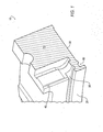
- FIG. 1 An enlarged isometric view of a cross section of a portion 10 of an embodiment of a seal ring segment that illustrates aspects of the disclosed concept is generally shown in FIG. 1 .
- the illustrated portion 10 includes a secondary sealing surface 20, a seal bore 30, a radial feed groove 40, a face groove 50, a radial seal dam relief groove 60, and a segment cross sectional surface 70.
- the disclosed face groove 50 may include one or more unique aspects and features.
- the axial depth of the radial feed groove 40 may be about 0.120 ⁇ 0.005 inches.
- embodiments of seal ring segments may include a plurality of radial feed grooves as desired or necessary to ensure/maintain a desired flow of fluid/air.
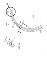
- FIGS. 2 and 3 illustrate views of a low pressure side and a high pressure side, respectively, of a seal ring segment 100 according to an embodiment of the disclosed concept.
- the seal ring segment 100 includes a radial external surface 120, and a radial internal surface 140 corresponding to a bore side of the segment.
- the seal ring segment 100 may additionally include at least one transition portion to serve to interface with and/or overlap with an adjacent segment.
- examples of first and second transition portions 150a, 150b are shown at each end of the segment 100.
- the seal ring segment 100 may further include a radial feed/anti-rotation groove 160 (also illustrated in the side view of that portion shown in FIG.
- the radial feed/anti-rotation groove 160 may have a depth D 1 .
- the depicted depth D 1 of the radial feed/anti-rotation groove 160 may have a depth of 0.110 ⁇ 0.005 inches.
- a significant portion of the flow of fluid/air may be associated with the radial feed/anti-rotation groove 160, the flow of which may be in direct communication with face groove 50. Seal ring segments associated with embodiments of the invention can be configured to address such a significant portion of flow, and the associated face groove can be configured to effectively provide a "reservoir" of fluid/air that can help prevent a choke in system/assembly flow.
- FIG. 4 depicts the bore region of a seal ring segment 100 of the type shown in FIGS. 2 and 3 , including one or more lift augmentation formations (also referred to as "pads") 170 on the internal (or bore-side) surface 140 of seal ring segment 100.
- the present invention is not limited to the disclosed form of pads 170, and one or more pads included on the bore-side may, for example, comprise various types steps or pads, including Rayleigh steps or pads, and pads with improved dynamic features. Examples of a radial seal segment having improved hydrodynamic features are disclosed in U.S. Patent No. 7,770,895 , US Patent No 5,509,664 , and U.S. Patent Application Publication No.
- the seal ring segment may generally have an overall width, depicted in FIG. 4 as width W 1 , of 0.230 ⁇ 0.002 inches. It is noted that each seal ring segment may cover a portion or angular segment of 360° degrees, which is commonly needed to provide a seal about a round or circular rotating member. In the embodiment illustrated in FIG. 3 , the illustrated angle ⁇ is approximately 120°. When a plurality of similar segments are involved, the angular range covered by each segment will typically be a subset of 360°, such as 72°, 90°, 120°, or 180°. Moreover, as generally indicated in FIG. 3 (i.e., the portion not included with ⁇ ), there may be a portion of each end of the segment that is intended to overlap or interconnect with an adjacent segment.
- FIG. 5 is an enlarged view of the end portion of the embodiment of a seal ring segment 100 shown in FIG. 2 .
- FIG. 6 is a cross sectional view of the end portion of the seal ring segment shown in FIG. 5 viewed along section line 6-6.
- the segment 100 may be provided with the following illustrated dimensions: W 2 of 0.040 ⁇ 0.005 inches; W 3 of 0.030 ⁇ 0.005 inches; L 1 of 0.065 ⁇ 0.005 inches; and D 2 of 0.015 ⁇ 0.005 inches.
- FIG. 7 an embodiment of a cross section of a seal ring segment - viewed along section line 7-7 shown in FIG. 3 - is generally shown.
- the illustrated portion of the seal ring segment 100 includes a secondary sealing surface 20, a seal bore 30, a radial feed groove 40 (identified in connection with the broken lines), a face groove 50, and a radial seal dam relief groove 60.
- FIG. 7 additionally illustrates several aspects/features that may be associated with a face groove 50 in accordance with teachings of the present disclosure.
- the face groove 50 may have an overall axial depth D 3 extending in the axial direction from the surface of the secondary sealing surface 20.
- the depth of the associated face groove is typically comparatively shallow, for example, about 0.015 inches deep, and is more in the nature of the same axial depth as that associated with the radial feed groove 40.
- the overall axial depth D 3 is greater than the axial depth of the radial feed groove 40.
- the overall axial depth D 3 may be at least twice the axial depth of the associated radial feed groove 40 and, for some embodiments, the overall axial depth D 3 may be at least three times the axial depth of the radial feed groove 40. In some embodiments, the overall axial depth D 3 may be about 0.025 inches or more.
- the overall axial depth D 3 may be about 0.050 ⁇ 0.003 inches.
- the radial feed groove and radial/anti-rotation groove can be configured to provide increased (and more than sufficient) communication of fluid/air between the operating source pressure and the outside pressure in the event of leakage past the secondary seal. Having a large axial feed groove volume (i.e., via face groove 50) can provide fluid accumulation to help ensure sufficient operating source pressure in the event of transient conditions.
- face groove 50 may include an entry portion 190 having an entry axial depth D 4 that extends in the axial direction from the surface of the secondary sealing surface 20.
- the entry portion 190 may have a height H 1, which may if desired by substantially constant for some or all of the axial depth of the entry portion 190. If desired the lowermost radial boundary (nearer the seal bore 30) may be substantially straight over its axial length.
- the entry axial depth D 4 may be about 0.023 ⁇ 0.008 inches, while the height H1 of the entry portion 190 may be about 0.062 ⁇ 0.004 inches.
- the face groove 50 may include a secondary portion or relief groove 180.
- a theoretical balance diameter of the segment for axial loading is generally designated BD.
- the relief groove 180 may axially offset from the secondary sealing surface 40, and may extend an additional distance D 5 beyond that of the entry axial depth D 4 .
- the relief groove 180 may include an undercut portion 200.
- the entry portion 190 may generally continue axially across (at the same level or slightly below) to the axial extent of the face groove (generally identified as 202).
- the relief groove 180 may have an undercut or reduced height H 3 with respect to the sealing surface 40 and/or the lowermost radial boundary (nearer the seal bore 30) of the entry portion 190. If desired, whether for manufacturing reasons to create the additional depth or otherwise, the lower boundary of the relief groove 180 may have curved shape, for example, as generally illustrated.
- D 5 may be about 0.027 ⁇ 0.005 inches
- H 2 may be about 0.060 ⁇ 0.003 inches
- H 3 may range from about 0.0100 inches to about 0.0140 inches.
- FIG. 8 is a cross sectional view of the embodiment of a seal ring segment shown in FIG. 7 , which generally illustrates the application of system pressures applied to two sides of the seal ring segment 100.
- P 1 generally represents system pressure applied to the secondary seal side of seal ring segment 100 up to the balance diameter (the theoretical balance diameter of the segment for axial loading is generally designated 210), and P 2 generally represents the unbalanced area where a pressure drop occurs from system pressure to ambient.
- P 3 On the opposing side of the seal ring segment 100, P 3 generally represents system pressure applied to the back of the seal ring segment.
- seal bore 30 may be of various standard configurations, or may include one or more hydrodynamic features.
- FIGS. 9 and 10 illustrate an example of a hydrodynamic feature that may be used in connection with a seal ring segment.
- a scooping groove 220 may be provided between a ramped portion 230 and a transverse groove 240.
- the disclosed concept is not limited to the illustrated configurations, and other variations - including hydrodynamic feature configurations - known to those of skill in the art may be utilized.
- FIG. 11 An example of a mating housing 250 for a segmented seal ring is generally illustrated in FIG. 11 .
- An enlarged view of a portion of the mating housing 250 is shown in FIG. 11 .
- the mating housing 250 may include an aperture, as generally illustrated (which can be configured to accept a pin or key associated with the seal ring segment), and a mating portion 260 that is intended to mate with a secondary sealing surface of a seal ring segment.
- a portion of the mating portion 260 may include a taper.
- the dimension of the taper T may be 0.0002 + 0.0002 inches.
- Standard design practice for segmented seals commonly assumes that system pressure is maintained in the face groove during operation.
- the force diagram included in FIG. 8 generally depicts the pressures/forces acting on the seal ring segment in the axial direction.
- the sealing surface on the housing may not (and generally cannot) be perfectly flat - and may in fact be intentionally tapered radially - a minute leak path may occur across the secondary sealing surface.
- conventional seal ring segments - which comparatively have a shallow face groove - there can be insufficient volume to keep up with the flow rate across the secondary sealing surface. As such, the pressure in a shallow groove may fall below that of the system pressure.
- the volume of the face groove may be ten times (or more) the volume of conventional (comparatively more shallow) face grooves.
- L BD 2 ⁇ seal bore 2 ⁇ ⁇ / 4 ⁇ system pressure ⁇ pressure profile
- the axial loading that is applied to the secondary sealing surface decreases.
- the reduction in axial loading reduces the radial force required for the segment to move radially.
- Such a reduction in radial force can, for example, improve the tracking ability for standard and arch-bound segmented seals.
- such a reduction in radial force can increase the predicted hydrodynamic air film by as much as 50% or more for a given hydrodynamic pad geometry on the seal bore (e.g., when used with seals operating at high pressure conditions).
- the addition of hydrodynamic features to the aforementioned face groove teachings can provide a segment that functions comparatively cooler operating seal temperatures and may therefore expand the operational life of the seal.
Landscapes
- Engineering & Computer Science (AREA)
- General Engineering & Computer Science (AREA)
- Mechanical Engineering (AREA)
- Sealing Devices (AREA)
- Gasket Seals (AREA)
Claims (13)
- Segment (100) einer Dichtungsanordnung zur Abdichtung gegen ein rotierendes Bauteil, wobei das Segment (100) versehen ist mit:einer radialen Außenfläche (120);einer radialen Innenfläche (140) zum Abdichtend gegen das rotierende Bauteil;einer Stirnseitennut (50);einer sekundären Dichtfläche (20); undeiner radialen Zufuhrnut (40);wobei die Stirnseitennut (50) eine axiale Tiefe von der Oberfläche der sekundären Dichtfläche (20) aufweist, die größer als die axiale Tiefe der radialen Zufuhrnut (40) ist; und wobei die Stirnseitennut (50) eine radiale Länge an der axialen Position der sekundären Dichtfläche (20) hat, dadurch gekennzeichnet dass die Stirnseitennut (50) einen sekundären Bereich (180) aufweist, der axial versetzt zu der sekundären Dichtfläche (20 ist und der eine radiale Länge hat, die größer als die radiale Länge der Stirnseitennut (50) an der axialen Position der sekundären Dichtfläche (20) ist.
- Segment (100) gemäß Anspruch 1, bei welchem die axiale Tiefe der Stirnseitennut (50) mindestens doppelt so groß wie die axiale Tiefe der radialen Zufuhrnut (40) ist.
- Segment (100) gemäß Anspruch 1, bei welchem die axiale Tiefe der Stirnseitennut (50) mindestens dreimal so groß wie die axiale Tiefe der radialen Zufuhrnut (40) ist.
- Segment (100) gemäß Anspruch 1, bei welchem die axiale Tiefe der Stirnseitennut (50) mindestens etwa 0,635 mm (0,025 Inch) beträgt.
- Segment (100) gemäß Anspruch 1, bei welchem die axiale Tiefe der Stirnseitennut (50) mindestens etwa 1,1938 mm (0,047 Inch) beträgt.
- Segment (100) gemäß Anspruch 1, bei welchem der sekundäre Bereich (180) der Stirnseitennut (50) einen unterschnittenen Bereich (200) aufweist.
- Segment (100) gemäß Anspruch 1, bei welchem die radiale Länge des sekundären Bereichs (180) der Stirnseitennut (50) mindestens etwa 0,254 mm (0,010 Inch) länger in der radialen Richtung als die radiale Länge der Stirnseitennut (50) an der axialen Position der sekundären Dichtfläche (20) ist.
- Segment (100) gemäß Anspruch 1, bei welchem die Stirnseitennut (50) einen Eintrittsbereich (190) und eine Entlastungsnut (60) aufweist.
- Segment (100) gemäß Anspruch 8, bei welchem die Entlastungsnut (60) um einen axialen Abstand von mindestens etwa 0,508 mm (0,020 Inch) zu der sekundären Dichtfläche (20) axial versetzt ist.
- Segment (100) gemäß Anspruch 1, bei welchem die radiale Innenfläche (30) ein hydrodynamisches Merkmal aufweist.
- Segment (100) gemäß Anspruch 10, bei welchem das hydrodynamische Merkmal mindestens eine oder mehrere Abhebeflächen (170) umfasst.
- Segment (100) gemäß Anspruch 1, bei welchem die axiale Tiefe der Stirnseitennut (50) etwa 1,27 mm ± 0,0762 mm (0,050 ± 0,003 Inch) beträgt.
- Segment (100) gemäß Anspruch 1, bei welchem die axiale Tiefe des sekundären Bereichs (180) der Stirnseitennut (50) etwa 0,6858 mm ± 0,127 mm (0,027 ± 0,005 Inch) beträgt.
Applications Claiming Priority (2)
| Application Number | Priority Date | Filing Date | Title |
|---|---|---|---|
| US13/038,798 US8905407B2 (en) | 2011-03-02 | 2011-03-02 | Segmented seal with axial load control feature |
| PCT/IB2012/000378 WO2012117292A1 (en) | 2011-03-02 | 2012-03-01 | Segmented seal with axial load control feature |
Publications (2)
| Publication Number | Publication Date |
|---|---|
| EP2681471A1 EP2681471A1 (de) | 2014-01-08 |
| EP2681471B1 true EP2681471B1 (de) | 2016-09-14 |
Family
ID=45932448
Family Applications (1)
| Application Number | Title | Priority Date | Filing Date |
|---|---|---|---|
| EP12712726.4A Not-in-force EP2681471B1 (de) | 2011-03-02 | 2012-03-01 | Segmentierte dichtung mit axialer laststeuerung |
Country Status (6)
| Country | Link |
|---|---|
| US (1) | US8905407B2 (de) |
| EP (1) | EP2681471B1 (de) |
| CN (1) | CN103429938B (de) |
| BR (1) | BR112013022245B1 (de) |
| CA (1) | CA2828384C (de) |
| WO (1) | WO2012117292A1 (de) |
Families Citing this family (12)
| Publication number | Priority date | Publication date | Assignee | Title |
|---|---|---|---|---|
| US9695940B2 (en) * | 2013-12-18 | 2017-07-04 | Kaydon Ring & Seal, Inc. | Bidirectional lift-off circumferential shaft seal segment and a shaft seal including a plurality of the segments |
| CN104481724A (zh) * | 2014-12-12 | 2015-04-01 | 张家港市三林法兰锻造有限公司 | 内燃机密封室 |
| US9638326B2 (en) * | 2014-12-15 | 2017-05-02 | Kaydon Ring & Seal, Inc. | Arch-bound ring seal and ring seal system including an arch-bound ring seal |
| US9927033B2 (en) * | 2015-06-29 | 2018-03-27 | Kaydon Ring & Seal, Inc. | Split circumferential lift-off seal segment |
| US10393272B2 (en) | 2015-11-24 | 2019-08-27 | Kaydon Ring & Seal, Inc. | Sleeve configured for use in a non-contacting gas seal and gas seal including the sleeve |
| US10670151B2 (en) | 2015-12-16 | 2020-06-02 | Eaton Intelligent Power Limited | Segmented seal with shallow groove |
| US10619742B2 (en) | 2017-07-14 | 2020-04-14 | United Technologies Corporation | Ring seal arrangement with installation foolproofing |
| US11060613B2 (en) * | 2017-11-27 | 2021-07-13 | Eaton Intelligent Power Limited | Radial segmented seal with air curtain generator |
| US11391377B2 (en) | 2019-11-15 | 2022-07-19 | Eaton Intelligent Power Limited | Hydraulic seal |
| JP7705708B2 (ja) | 2019-12-19 | 2025-07-10 | イートン インテリジェント パワー リミテッド | 自己矯正流体力学的シール |
| US11713688B2 (en) | 2021-12-03 | 2023-08-01 | Raytheon Technologies Corporation | Pressure-balanced carbon seal |
| US11892083B2 (en) * | 2022-04-06 | 2024-02-06 | Rtx Corporation | Piston seal ring |
Family Cites Families (25)
| Publication number | Priority date | Publication date | Assignee | Title |
|---|---|---|---|---|
| US770895A (en) * | 1904-04-22 | 1904-09-27 | William P Elliott | Gate. |
| US1999094A (en) * | 1933-10-31 | 1935-04-23 | William G G Godron | Sealing device, packing and the like |
| US3575424A (en) * | 1969-11-28 | 1971-04-20 | Koppers Co Inc | Pressure balanced circumferential seal assembly |
| CH582319A5 (de) * | 1975-03-05 | 1976-11-30 | Bbc Brown Boveri & Cie | |
| US4082296A (en) * | 1976-05-26 | 1978-04-04 | Stein Philip C | Seal for sealing between a rotating member and a housing |
| US4211424A (en) * | 1979-04-16 | 1980-07-08 | Stein Philip C | Centrifugally compensated seal for sealing between concentric shafts |
| US4971306A (en) * | 1987-12-25 | 1990-11-20 | Eagle Industry Co., Ltd. | Seals for cylindrical surfaces |
| JP2648816B2 (ja) * | 1988-05-10 | 1997-09-03 | イーグル工業株式会社 | 円筒面シール |
| US5100158A (en) * | 1990-08-16 | 1992-03-31 | Eg&G Sealol, Inc. | Compliant finer seal |
| US5169159A (en) * | 1991-09-30 | 1992-12-08 | General Electric Company | Effective sealing device for engine flowpath |
| US5509664A (en) * | 1993-07-19 | 1996-04-23 | Stein Seal Company | Segmented hydrodynamic seals for sealing a rotatable shaft |
| US5516118A (en) * | 1993-07-19 | 1996-05-14 | Stein Seal Company | Circumferential hydrodynamic seals for sealing a bidirectionally rotatable member |
| US5558341A (en) * | 1995-01-11 | 1996-09-24 | Stein Seal Company | Seal for sealing an incompressible fluid between a relatively stationary seal and a movable member |
| US6145843A (en) * | 1998-10-19 | 2000-11-14 | Stein Seal Company | Hydrodynamic lift seal for use with compressible fluids |
| US7044470B2 (en) * | 2000-07-12 | 2006-05-16 | Perkinelmer, Inc. | Rotary face seal assembly |
| GB2368100B (en) * | 2000-10-19 | 2004-02-18 | Rolls Royce Plc | Seal fitting |
| US6692006B2 (en) * | 2001-10-15 | 2004-02-17 | Stein Seal Company | High-pressure film-riding seals for rotating shafts |
| US6637753B2 (en) * | 2001-12-28 | 2003-10-28 | General Electric Company | Supplemental seal for the chordal hinge seals in a gas turbine |
| US6648332B1 (en) * | 2002-07-29 | 2003-11-18 | General Electric Company | Steam turbine packing casing horizontal joint seals and methods of forming the seals |
| US8091897B2 (en) * | 2006-05-17 | 2012-01-10 | A.W. Chesterton Company | Mechanical seal assembly |
| US20080284105A1 (en) * | 2006-06-21 | 2008-11-20 | Thurai Manik Vasagar | Low and reverse pressure application hydrodynamic pressurizing seals |
| US7770895B2 (en) * | 2007-05-01 | 2010-08-10 | Eaton Corporation | Segmented seal portion and assembly |
| US20090206554A1 (en) * | 2008-02-18 | 2009-08-20 | Mark Kevin Bowen | Steam turbine engine and method of assembling same |
| US7914007B2 (en) * | 2008-12-30 | 2011-03-29 | Eaton Corporation | Segmented seal with hydrodynamic feature and assembly |
| WO2011025484A1 (en) * | 2009-08-27 | 2011-03-03 | Stein Seal Company | Hydrodynamic circumferential seal system for large translations |
-
2011
- 2011-03-02 US US13/038,798 patent/US8905407B2/en active Active
-
2012
- 2012-03-01 EP EP12712726.4A patent/EP2681471B1/de not_active Not-in-force
- 2012-03-01 WO PCT/IB2012/000378 patent/WO2012117292A1/en not_active Ceased
- 2012-03-01 BR BR112013022245-0A patent/BR112013022245B1/pt not_active IP Right Cessation
- 2012-03-01 CA CA2828384A patent/CA2828384C/en active Active
- 2012-03-01 CN CN201280011297.0A patent/CN103429938B/zh not_active Expired - Fee Related
Also Published As
| Publication number | Publication date |
|---|---|
| EP2681471A1 (de) | 2014-01-08 |
| US8905407B2 (en) | 2014-12-09 |
| WO2012117292A1 (en) | 2012-09-07 |
| CN103429938A (zh) | 2013-12-04 |
| BR112013022245A2 (pt) | 2020-09-01 |
| CA2828384C (en) | 2016-09-06 |
| US20120223490A1 (en) | 2012-09-06 |
| BR112013022245B1 (pt) | 2021-06-29 |
| CN103429938B (zh) | 2016-11-23 |
| CA2828384A1 (en) | 2012-09-07 |
Similar Documents
| Publication | Publication Date | Title |
|---|---|---|
| EP2681471B1 (de) | Segmentierte dichtung mit axialer laststeuerung | |
| EP2376822B1 (de) | Segmentierte dichtung mit einem hydrodynamischen merkmal und anordnung | |
| EP3553353B1 (de) | Gleitkomponente | |
| EP2977654B1 (de) | Gleitkomponente | |
| EP1988313B1 (de) | Segmentiertes Dichtungselement und Baugruppe | |
| EP3677802B1 (de) | Schiebeteil | |
| EP3315832B1 (de) | Gleitkomponente | |
| EP3321548B1 (de) | Schiebeteil | |
| EP2350503B1 (de) | Hydrodynamisches rundumversiegelungssystem für sehr grosse getriebe | |
| EP2853786B1 (de) | Gleitkomponente | |
| EP2853787B1 (de) | Gleitkomponente | |
| EP3627011B1 (de) | Gleitkomponente | |
| EP3196516A1 (de) | Gleitkomponente | |
| EP3872375B1 (de) | Gleitelement | |
| US20080157479A1 (en) | Low and reverse pressure application hydrodynamic pressurizing seals | |
| EP2948682B1 (de) | Getriebeausgangsdichtung | |
| US11287043B2 (en) | High clearance seal assembly | |
| US10876634B2 (en) | Annular sealing assembly | |
| US20170307085A1 (en) | Circumferential shaft seal with radial displacement control | |
| US10036474B2 (en) | Vented lift off seal assemblies |
Legal Events
| Date | Code | Title | Description |
|---|---|---|---|
| PUAI | Public reference made under article 153(3) epc to a published international application that has entered the european phase |
Free format text: ORIGINAL CODE: 0009012 |
|
| 17P | Request for examination filed |
Effective date: 20131002 |
|
| AK | Designated contracting states |
Kind code of ref document: A1 Designated state(s): AL AT BE BG CH CY CZ DE DK EE ES FI FR GB GR HR HU IE IS IT LI LT LU LV MC MK MT NL NO PL PT RO RS SE SI SK SM TR |
|
| DAX | Request for extension of the european patent (deleted) | ||
| GRAP | Despatch of communication of intention to grant a patent |
Free format text: ORIGINAL CODE: EPIDOSNIGR1 |
|
| INTG | Intention to grant announced |
Effective date: 20160429 |
|
| GRAS | Grant fee paid |
Free format text: ORIGINAL CODE: EPIDOSNIGR3 |
|
| GRAA | (expected) grant |
Free format text: ORIGINAL CODE: 0009210 |
|
| RAP1 | Party data changed (applicant data changed or rights of an application transferred) |
Owner name: EATON CORPORATION |
|
| AK | Designated contracting states |
Kind code of ref document: B1 Designated state(s): AL AT BE BG CH CY CZ DE DK EE ES FI FR GB GR HR HU IE IS IT LI LT LU LV MC MK MT NL NO PL PT RO RS SE SI SK SM TR |
|
| REG | Reference to a national code |
Ref country code: GB Ref legal event code: FG4D |
|
| REG | Reference to a national code |
Ref country code: CH Ref legal event code: EP |
|
| REG | Reference to a national code |
Ref country code: IE Ref legal event code: FG4D |
|
| REG | Reference to a national code |
Ref country code: AT Ref legal event code: REF Ref document number: 829380 Country of ref document: AT Kind code of ref document: T Effective date: 20161015 |
|
| REG | Reference to a national code |
Ref country code: DE Ref legal event code: R096 Ref document number: 602012022805 Country of ref document: DE |
|
| REG | Reference to a national code |
Ref country code: LT Ref legal event code: MG4D |
|
| REG | Reference to a national code |
Ref country code: NL Ref legal event code: MP Effective date: 20160914 |
|
| PG25 | Lapsed in a contracting state [announced via postgrant information from national office to epo] |
Ref country code: HR Free format text: LAPSE BECAUSE OF FAILURE TO SUBMIT A TRANSLATION OF THE DESCRIPTION OR TO PAY THE FEE WITHIN THE PRESCRIBED TIME-LIMIT Effective date: 20160914 Ref country code: NO Free format text: LAPSE BECAUSE OF FAILURE TO SUBMIT A TRANSLATION OF THE DESCRIPTION OR TO PAY THE FEE WITHIN THE PRESCRIBED TIME-LIMIT Effective date: 20161214 Ref country code: LT Free format text: LAPSE BECAUSE OF FAILURE TO SUBMIT A TRANSLATION OF THE DESCRIPTION OR TO PAY THE FEE WITHIN THE PRESCRIBED TIME-LIMIT Effective date: 20160914 Ref country code: RS Free format text: LAPSE BECAUSE OF FAILURE TO SUBMIT A TRANSLATION OF THE DESCRIPTION OR TO PAY THE FEE WITHIN THE PRESCRIBED TIME-LIMIT Effective date: 20160914 Ref country code: FI Free format text: LAPSE BECAUSE OF FAILURE TO SUBMIT A TRANSLATION OF THE DESCRIPTION OR TO PAY THE FEE WITHIN THE PRESCRIBED TIME-LIMIT Effective date: 20160914 |
|
| REG | Reference to a national code |
Ref country code: AT Ref legal event code: MK05 Ref document number: 829380 Country of ref document: AT Kind code of ref document: T Effective date: 20160914 |
|
| REG | Reference to a national code |
Ref country code: FR Ref legal event code: PLFP Year of fee payment: 6 |
|
| PG25 | Lapsed in a contracting state [announced via postgrant information from national office to epo] |
Ref country code: GR Free format text: LAPSE BECAUSE OF FAILURE TO SUBMIT A TRANSLATION OF THE DESCRIPTION OR TO PAY THE FEE WITHIN THE PRESCRIBED TIME-LIMIT Effective date: 20161215 Ref country code: SE Free format text: LAPSE BECAUSE OF FAILURE TO SUBMIT A TRANSLATION OF THE DESCRIPTION OR TO PAY THE FEE WITHIN THE PRESCRIBED TIME-LIMIT Effective date: 20160914 Ref country code: LV Free format text: LAPSE BECAUSE OF FAILURE TO SUBMIT A TRANSLATION OF THE DESCRIPTION OR TO PAY THE FEE WITHIN THE PRESCRIBED TIME-LIMIT Effective date: 20160914 Ref country code: NL Free format text: LAPSE BECAUSE OF FAILURE TO SUBMIT A TRANSLATION OF THE DESCRIPTION OR TO PAY THE FEE WITHIN THE PRESCRIBED TIME-LIMIT Effective date: 20160914 |
|
| PG25 | Lapsed in a contracting state [announced via postgrant information from national office to epo] |
Ref country code: RO Free format text: LAPSE BECAUSE OF FAILURE TO SUBMIT A TRANSLATION OF THE DESCRIPTION OR TO PAY THE FEE WITHIN THE PRESCRIBED TIME-LIMIT Effective date: 20160914 Ref country code: EE Free format text: LAPSE BECAUSE OF FAILURE TO SUBMIT A TRANSLATION OF THE DESCRIPTION OR TO PAY THE FEE WITHIN THE PRESCRIBED TIME-LIMIT Effective date: 20160914 |
|
| PG25 | Lapsed in a contracting state [announced via postgrant information from national office to epo] |
Ref country code: SM Free format text: LAPSE BECAUSE OF FAILURE TO SUBMIT A TRANSLATION OF THE DESCRIPTION OR TO PAY THE FEE WITHIN THE PRESCRIBED TIME-LIMIT Effective date: 20160914 Ref country code: PT Free format text: LAPSE BECAUSE OF FAILURE TO SUBMIT A TRANSLATION OF THE DESCRIPTION OR TO PAY THE FEE WITHIN THE PRESCRIBED TIME-LIMIT Effective date: 20170116 Ref country code: PL Free format text: LAPSE BECAUSE OF FAILURE TO SUBMIT A TRANSLATION OF THE DESCRIPTION OR TO PAY THE FEE WITHIN THE PRESCRIBED TIME-LIMIT Effective date: 20160914 Ref country code: CZ Free format text: LAPSE BECAUSE OF FAILURE TO SUBMIT A TRANSLATION OF THE DESCRIPTION OR TO PAY THE FEE WITHIN THE PRESCRIBED TIME-LIMIT Effective date: 20160914 Ref country code: ES Free format text: LAPSE BECAUSE OF FAILURE TO SUBMIT A TRANSLATION OF THE DESCRIPTION OR TO PAY THE FEE WITHIN THE PRESCRIBED TIME-LIMIT Effective date: 20160914 Ref country code: BE Free format text: LAPSE BECAUSE OF FAILURE TO SUBMIT A TRANSLATION OF THE DESCRIPTION OR TO PAY THE FEE WITHIN THE PRESCRIBED TIME-LIMIT Effective date: 20160914 Ref country code: IS Free format text: LAPSE BECAUSE OF FAILURE TO SUBMIT A TRANSLATION OF THE DESCRIPTION OR TO PAY THE FEE WITHIN THE PRESCRIBED TIME-LIMIT Effective date: 20170114 Ref country code: AT Free format text: LAPSE BECAUSE OF FAILURE TO SUBMIT A TRANSLATION OF THE DESCRIPTION OR TO PAY THE FEE WITHIN THE PRESCRIBED TIME-LIMIT Effective date: 20160914 Ref country code: BG Free format text: LAPSE BECAUSE OF FAILURE TO SUBMIT A TRANSLATION OF THE DESCRIPTION OR TO PAY THE FEE WITHIN THE PRESCRIBED TIME-LIMIT Effective date: 20161214 Ref country code: SK Free format text: LAPSE BECAUSE OF FAILURE TO SUBMIT A TRANSLATION OF THE DESCRIPTION OR TO PAY THE FEE WITHIN THE PRESCRIBED TIME-LIMIT Effective date: 20160914 |
|
| REG | Reference to a national code |
Ref country code: DE Ref legal event code: R097 Ref document number: 602012022805 Country of ref document: DE |
|
| PG25 | Lapsed in a contracting state [announced via postgrant information from national office to epo] |
Ref country code: IT Free format text: LAPSE BECAUSE OF FAILURE TO SUBMIT A TRANSLATION OF THE DESCRIPTION OR TO PAY THE FEE WITHIN THE PRESCRIBED TIME-LIMIT Effective date: 20160914 |
|
| PLBE | No opposition filed within time limit |
Free format text: ORIGINAL CODE: 0009261 |
|
| STAA | Information on the status of an ep patent application or granted ep patent |
Free format text: STATUS: NO OPPOSITION FILED WITHIN TIME LIMIT |
|
| PG25 | Lapsed in a contracting state [announced via postgrant information from national office to epo] |
Ref country code: DK Free format text: LAPSE BECAUSE OF FAILURE TO SUBMIT A TRANSLATION OF THE DESCRIPTION OR TO PAY THE FEE WITHIN THE PRESCRIBED TIME-LIMIT Effective date: 20160914 |
|
| 26N | No opposition filed |
Effective date: 20170615 |
|
| REG | Reference to a national code |
Ref country code: CH Ref legal event code: PL |
|
| PG25 | Lapsed in a contracting state [announced via postgrant information from national office to epo] |
Ref country code: SI Free format text: LAPSE BECAUSE OF FAILURE TO SUBMIT A TRANSLATION OF THE DESCRIPTION OR TO PAY THE FEE WITHIN THE PRESCRIBED TIME-LIMIT Effective date: 20160914 Ref country code: MC Free format text: LAPSE BECAUSE OF FAILURE TO SUBMIT A TRANSLATION OF THE DESCRIPTION OR TO PAY THE FEE WITHIN THE PRESCRIBED TIME-LIMIT Effective date: 20160914 |
|
| REG | Reference to a national code |
Ref country code: IE Ref legal event code: MM4A |
|
| PG25 | Lapsed in a contracting state [announced via postgrant information from national office to epo] |
Ref country code: LU Free format text: LAPSE BECAUSE OF NON-PAYMENT OF DUE FEES Effective date: 20170301 |
|
| REG | Reference to a national code |
Ref country code: FR Ref legal event code: PLFP Year of fee payment: 7 |
|
| PG25 | Lapsed in a contracting state [announced via postgrant information from national office to epo] |
Ref country code: IE Free format text: LAPSE BECAUSE OF NON-PAYMENT OF DUE FEES Effective date: 20170301 Ref country code: LI Free format text: LAPSE BECAUSE OF NON-PAYMENT OF DUE FEES Effective date: 20170331 Ref country code: CH Free format text: LAPSE BECAUSE OF NON-PAYMENT OF DUE FEES Effective date: 20170331 |
|
| PG25 | Lapsed in a contracting state [announced via postgrant information from national office to epo] |
Ref country code: MT Free format text: LAPSE BECAUSE OF NON-PAYMENT OF DUE FEES Effective date: 20170301 |
|
| PG25 | Lapsed in a contracting state [announced via postgrant information from national office to epo] |
Ref country code: AL Free format text: LAPSE BECAUSE OF FAILURE TO SUBMIT A TRANSLATION OF THE DESCRIPTION OR TO PAY THE FEE WITHIN THE PRESCRIBED TIME-LIMIT Effective date: 20160914 |
|
| REG | Reference to a national code |
Ref country code: GB Ref legal event code: 732E Free format text: REGISTERED BETWEEN 20181115 AND 20181130 |
|
| REG | Reference to a national code |
Ref country code: DE Ref legal event code: R082 Ref document number: 602012022805 Country of ref document: DE Ref country code: DE Ref legal event code: R081 Ref document number: 602012022805 Country of ref document: DE Owner name: EATON INTELLIGENT POWER LIMITED, IE Free format text: FORMER OWNER: EATON CORPORATION, CLEVELAND, OHIO, US |
|
| PG25 | Lapsed in a contracting state [announced via postgrant information from national office to epo] |
Ref country code: HU Free format text: LAPSE BECAUSE OF FAILURE TO SUBMIT A TRANSLATION OF THE DESCRIPTION OR TO PAY THE FEE WITHIN THE PRESCRIBED TIME-LIMIT; INVALID AB INITIO Effective date: 20120301 |
|
| PG25 | Lapsed in a contracting state [announced via postgrant information from national office to epo] |
Ref country code: CY Free format text: LAPSE BECAUSE OF NON-PAYMENT OF DUE FEES Effective date: 20160914 |
|
| PG25 | Lapsed in a contracting state [announced via postgrant information from national office to epo] |
Ref country code: MK Free format text: LAPSE BECAUSE OF FAILURE TO SUBMIT A TRANSLATION OF THE DESCRIPTION OR TO PAY THE FEE WITHIN THE PRESCRIBED TIME-LIMIT Effective date: 20160914 |
|
| PG25 | Lapsed in a contracting state [announced via postgrant information from national office to epo] |
Ref country code: TR Free format text: LAPSE BECAUSE OF FAILURE TO SUBMIT A TRANSLATION OF THE DESCRIPTION OR TO PAY THE FEE WITHIN THE PRESCRIBED TIME-LIMIT Effective date: 20160914 |
|
| P01 | Opt-out of the competence of the unified patent court (upc) registered |
Effective date: 20230521 |
|
| PGFP | Annual fee paid to national office [announced via postgrant information from national office to epo] |
Ref country code: DE Payment date: 20240220 Year of fee payment: 13 Ref country code: GB Payment date: 20240220 Year of fee payment: 13 |
|
| PGFP | Annual fee paid to national office [announced via postgrant information from national office to epo] |
Ref country code: FR Payment date: 20240221 Year of fee payment: 13 |
|
| REG | Reference to a national code |
Ref country code: DE Ref legal event code: R119 Ref document number: 602012022805 Country of ref document: DE |
|
| GBPC | Gb: european patent ceased through non-payment of renewal fee |
Effective date: 20250301 |
|
| PG25 | Lapsed in a contracting state [announced via postgrant information from national office to epo] |
Ref country code: DE Free format text: LAPSE BECAUSE OF NON-PAYMENT OF DUE FEES Effective date: 20251001 |
|
| PG25 | Lapsed in a contracting state [announced via postgrant information from national office to epo] |
Ref country code: GB Free format text: LAPSE BECAUSE OF NON-PAYMENT OF DUE FEES Effective date: 20250301 |
|
| PG25 | Lapsed in a contracting state [announced via postgrant information from national office to epo] |
Ref country code: FR Free format text: LAPSE BECAUSE OF NON-PAYMENT OF DUE FEES Effective date: 20250331 |