EP2682044A1 - Endoskopsystem, Prozessorvorrichtung dafür und Verfahren zur Steuerung des Endoskopsystems - Google Patents
Endoskopsystem, Prozessorvorrichtung dafür und Verfahren zur Steuerung des Endoskopsystems Download PDFInfo
- Publication number
- EP2682044A1 EP2682044A1 EP13175345.1A EP13175345A EP2682044A1 EP 2682044 A1 EP2682044 A1 EP 2682044A1 EP 13175345 A EP13175345 A EP 13175345A EP 2682044 A1 EP2682044 A1 EP 2682044A1
- Authority
- EP
- European Patent Office
- Prior art keywords
- special
- image sensor
- image
- light
- light amount
- Prior art date
- Legal status (The legal status is an assumption and is not a legal conclusion. Google has not performed a legal analysis and makes no representation as to the accuracy of the status listed.)
- Granted
Links
Images










Classifications
-
- A—HUMAN NECESSITIES
- A61—MEDICAL OR VETERINARY SCIENCE; HYGIENE
- A61B—DIAGNOSIS; SURGERY; IDENTIFICATION
- A61B1/00—Instruments for performing medical examinations of the interior of cavities or tubes of the body by visual or photographical inspection, e.g. endoscopes; Illuminating arrangements therefor
- A61B1/00002—Operational features of endoscopes
- A61B1/00004—Operational features of endoscopes characterised by electronic signal processing
- A61B1/00009—Operational features of endoscopes characterised by electronic signal processing of image signals during a use of endoscope
- A61B1/000094—Operational features of endoscopes characterised by electronic signal processing of image signals during a use of endoscope extracting biological structures
-
- A—HUMAN NECESSITIES
- A61—MEDICAL OR VETERINARY SCIENCE; HYGIENE
- A61B—DIAGNOSIS; SURGERY; IDENTIFICATION
- A61B1/00—Instruments for performing medical examinations of the interior of cavities or tubes of the body by visual or photographical inspection, e.g. endoscopes; Illuminating arrangements therefor
- A61B1/04—Instruments for performing medical examinations of the interior of cavities or tubes of the body by visual or photographical inspection, e.g. endoscopes; Illuminating arrangements therefor combined with photographic or television appliances
- A61B1/043—Instruments for performing medical examinations of the interior of cavities or tubes of the body by visual or photographical inspection, e.g. endoscopes; Illuminating arrangements therefor combined with photographic or television appliances for fluorescence imaging
-
- A—HUMAN NECESSITIES
- A61—MEDICAL OR VETERINARY SCIENCE; HYGIENE
- A61B—DIAGNOSIS; SURGERY; IDENTIFICATION
- A61B1/00—Instruments for performing medical examinations of the interior of cavities or tubes of the body by visual or photographical inspection, e.g. endoscopes; Illuminating arrangements therefor
- A61B1/06—Instruments for performing medical examinations of the interior of cavities or tubes of the body by visual or photographical inspection, e.g. endoscopes; Illuminating arrangements therefor with illuminating arrangements
- A61B1/0638—Instruments for performing medical examinations of the interior of cavities or tubes of the body by visual or photographical inspection, e.g. endoscopes; Illuminating arrangements therefor with illuminating arrangements providing two or more wavelengths
-
- A—HUMAN NECESSITIES
- A61—MEDICAL OR VETERINARY SCIENCE; HYGIENE
- A61B—DIAGNOSIS; SURGERY; IDENTIFICATION
- A61B1/00—Instruments for performing medical examinations of the interior of cavities or tubes of the body by visual or photographical inspection, e.g. endoscopes; Illuminating arrangements therefor
- A61B1/06—Instruments for performing medical examinations of the interior of cavities or tubes of the body by visual or photographical inspection, e.g. endoscopes; Illuminating arrangements therefor with illuminating arrangements
- A61B1/0653—Instruments for performing medical examinations of the interior of cavities or tubes of the body by visual or photographical inspection, e.g. endoscopes; Illuminating arrangements therefor with illuminating arrangements with wavelength conversion
-
- A—HUMAN NECESSITIES
- A61—MEDICAL OR VETERINARY SCIENCE; HYGIENE
- A61B—DIAGNOSIS; SURGERY; IDENTIFICATION
- A61B1/00—Instruments for performing medical examinations of the interior of cavities or tubes of the body by visual or photographical inspection, e.g. endoscopes; Illuminating arrangements therefor
- A61B1/06—Instruments for performing medical examinations of the interior of cavities or tubes of the body by visual or photographical inspection, e.g. endoscopes; Illuminating arrangements therefor with illuminating arrangements
- A61B1/0655—Control therefor
-
- A—HUMAN NECESSITIES
- A61—MEDICAL OR VETERINARY SCIENCE; HYGIENE
- A61B—DIAGNOSIS; SURGERY; IDENTIFICATION
- A61B5/00—Measuring for diagnostic purposes; Identification of persons
- A61B5/145—Measuring characteristics of blood in vivo, e.g. gas concentration or pH-value ; Measuring characteristics of body fluids or tissues, e.g. interstitial fluid or cerebral tissue
- A61B5/1455—Measuring characteristics of blood in vivo, e.g. gas concentration or pH-value ; Measuring characteristics of body fluids or tissues, e.g. interstitial fluid or cerebral tissue using optical sensors, e.g. spectral photometrical oximeters
- A61B5/14551—Measuring characteristics of blood in vivo, e.g. gas concentration or pH-value ; Measuring characteristics of body fluids or tissues, e.g. interstitial fluid or cerebral tissue using optical sensors, e.g. spectral photometrical oximeters for measuring blood gases
-
- A—HUMAN NECESSITIES
- A61—MEDICAL OR VETERINARY SCIENCE; HYGIENE
- A61B—DIAGNOSIS; SURGERY; IDENTIFICATION
- A61B5/00—Measuring for diagnostic purposes; Identification of persons
- A61B5/145—Measuring characteristics of blood in vivo, e.g. gas concentration or pH-value ; Measuring characteristics of body fluids or tissues, e.g. interstitial fluid or cerebral tissue
- A61B5/1455—Measuring characteristics of blood in vivo, e.g. gas concentration or pH-value ; Measuring characteristics of body fluids or tissues, e.g. interstitial fluid or cerebral tissue using optical sensors, e.g. spectral photometrical oximeters
- A61B5/1459—Measuring characteristics of blood in vivo, e.g. gas concentration or pH-value ; Measuring characteristics of body fluids or tissues, e.g. interstitial fluid or cerebral tissue using optical sensors, e.g. spectral photometrical oximeters invasive, e.g. introduced into the body by a catheter
-
- A—HUMAN NECESSITIES
- A61—MEDICAL OR VETERINARY SCIENCE; HYGIENE
- A61B—DIAGNOSIS; SURGERY; IDENTIFICATION
- A61B1/00—Instruments for performing medical examinations of the interior of cavities or tubes of the body by visual or photographical inspection, e.g. endoscopes; Illuminating arrangements therefor
- A61B1/04—Instruments for performing medical examinations of the interior of cavities or tubes of the body by visual or photographical inspection, e.g. endoscopes; Illuminating arrangements therefor combined with photographic or television appliances
- A61B1/05—Instruments for performing medical examinations of the interior of cavities or tubes of the body by visual or photographical inspection, e.g. endoscopes; Illuminating arrangements therefor combined with photographic or television appliances characterised by the image sensor, e.g. camera, being in the distal end portion
Definitions
- the present invention relates to an endoscope system that obtains information about blood such as an oxygen saturation level of blood, a processor device of the endoscope system, and a method for controlling the endoscope system.
- an endoscope system In a medical field, an endoscope system is used often for diagnosis and treatment.
- the endoscope system is constituted of an electronic endoscope to be inserted into a human body cavity, a light source device for supplying illumination light to the electronic endoscope, and a processor device that processes an image signal produced by the electronic endoscope and displays a processed image on a monitor.
- an endoscope system that carries out not only normal observation for imaging an internal body portion under irradiation with white light (normal light), but also special observation for imaging the internal body portion under irradiation with specific narrow band light (special light).
- an oxygen saturation level obtaining technique is known using first light being narrow band light having a wavelength range in which an absorption coefficient is different between oxyhemoglobin and deoxyhemoglobin, and second light having a wavelength range different from that of the first light.
- the first and second light is applied sequentially to the internal body portion in order to determine an oxygen saturation level of blood.
- the determined oxygen saturation level is reflected in a normal image obtained in the normal observation, to produce a special image in which a hypoxic region being a cancer-suspected lesion is colored artificially.
- the normal image mainly aims to look at details of mucosal structure, including blood vessels, projections and depressions, and the like.
- the normal image requires high resolution.
- the hypoxic region extends a certain size, so the high resolution is not required.
- the special image requires high sensitivity to reflected light, because the oxygen saturation level is calculated from the light amount of the first and second light reflected from the internal body portion. For this reason, high-intensity narrow band light emitted from an LD, LED, or light source rivaling the LD or LED is needed as the first and second light. In the case of not using the high-intensity narrow band light, a high-sensitivity image sensor becomes necessary.
- US Patent Application Publication No. 2010/0245551 discloses an endoscope system that is provided with two image sensors i.e. a normal image sensor having normal sensitivity and a high-sensitivity image sensor having high sensitivity.
- the normal image sensor is used in the normal observation requiring high resolution
- the high-sensitivity image sensor is used in the special observation requiring high sensitivity.
- the high-sensitivity image sensor is used for detecting weak autofluorescence distributed through a wide wavelength range.
- the first and second light used for calculation of the oxygen saturation level has the specific wavelength ranges, so the light amount of the first and second light is not as low as that of the autofluorescence, though is lower than that of the white light. Therefore, in a short-distance view in which a distal end portion of the electronic endoscope is near the body portion, even the normal sensor can detect an enough light amount to calculate the oxygen saturation level.
- the normal sensor is adequate, it is desirable to use the normal image sensor having high resolution, instead of the high-sensitivity image sensor.
- An object of the present invention is to provide an endoscope system that can produce a special image having as high resolution as possible, while securing sensitivity required for calculating an oxygen saturation level of blood, a processor device of the endoscope system, and a method for controlling the endoscope system.
- an endoscope system includes a lighting means, an imaging means, a light amount evaluation means, a sensitizing means, and a special image processing means.
- the lighting means applies special illumination light to a body portion.
- the special illumination light has a wavelength at which oxyhemoglobin and deoxyhemoglobin have different absorption coefficients.
- the imaging means captures the special illumination light reflected from the body portion and produces a special signal.
- the light amount evaluation means measures a reflected light amount of the special illumination light based on the special signal, and judges whether or not the reflected light amount is low.
- the sensitizing means sensitizes the special signal, when the reflected light amount is judged to be low.
- the special image processing means measures an oxygen saturation level of blood based on the special signal that is sensitized or not sensitized in accordance with a judgment result of the light amount evaluation means, and produces a special image depicting the oxygen saturation level.
- the imaging means preferably includes first and second image sensors having different sensitivities.
- the second image sensor has higher sensitivity than the first image sensor.
- One of the first and second image sensors is preferably used in accordance with the judgment result of the light amount evaluation means.
- the sensitizing means preferably includes a binning processor for applying a binning process to the special signal.
- the binning processor may vary a level of the binning process in accordance with the reflected light amount of the special illumination light.
- the binning process may be performed in the second image sensor.
- the lighting means may sequentially apply normal illumination light having a broad wavelength band and the special illumination light to the body portion.
- the first image sensor may capture an image of the body portion under irradiation with the normal illumination light and output a color normal signal.
- the second image sensor may capture an image of the body portion under irradiation with the special illumination light and output the special signal.
- the special image processing means may produce the special image based on the special signal and a specific color signal of the color normal signal.
- the binning processor preferably applies the binning process to the special signal, when the reflected light amount is judged to be low.
- the special image processing means preferably equalizes a pixel number between the specific color signal and the special signal after being subjected to the binning process, so that a display area of the specific color signal coincides with a display area of the special signal after the binning process.
- the sensitizing means preferably includes an exposure time controller for making an exposure time of the second image sensor longer than an exposure time of the first image sensor, when the reflected light amount is judged to be low.
- the exposure time controller preferably varies the exposure time of the second image sensor in accordance with a degree of lowness of the reflected light amount.
- the sensitizing means may start sensitization. In a case where the special signal is sensitized, when the reflected light amount of the special illumination light is more than a second threshold value being larger than the first threshold value, the sensitizing means may stop the sensitization.
- the special illumination light is preferably narrow band light having the wavelength at which oxyhemoglobin and deoxyhemoglobin have different absorption coefficients.
- a processor device of an endoscope system includes a light amount evaluation means, a sensitizing means, and a special image processing means.
- the light amount evaluation means measures a reflected light amount of the special illumination light based on the special signal, and judges whether or not the reflected light amount is low.
- the sensitizing means sensitizes the special signal, when the reflected light amount is judged to be low.
- the special image processing means measures an oxygen saturation level of blood based on the special signal that is sensitized or not sensitized in accordance with a judgment result of the light amount evaluation means, and produces a special image depicting the oxygen saturation level.
- a method for controlling an endoscope system includes the steps of applying to a body portion special illumination light having a wavelength at which oxyhemoglobin and deoxyhemoglobin have different absorption coefficients; capturing by an imaging means the special illumination light reflected from the body portion and producing a special signal; measuring a reflected light amount of the special illumination light based on the special signal; judging whether or not the reflected light amount is low; sensitizing the special signal, when the reflected light amount is judged to be low; measuring an oxygen saturation level of blood based on the special signal that is sensitized or not sensitized in accordance with a result of the judgment; and producing a special image depicting the oxygen saturation level.
- the special signal is sensitized only when the reflected light amount of the special illumination light is judged to be low. Therefore, it is possible to produce the special image having as high resolution as possible, while securing sensitivity required for calculating the oxygen saturation level.
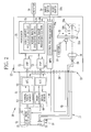
- an endoscope system 10 is constituted of an electronic endoscope 11, a processor device 12, a light source device 13, a monitor 14, and an input device 15 including a keyboard, a mouse, and the like.
- the electronic endoscope 11 images an internal body portion.
- the processor device 12 applies image processing to an image signal obtained by the electronic endoscope 11.
- the light source device 13 supplies illumination light to the internal body portion. A produced image is displayed on the monitor 14.
- the endoscope system 10 has a normal mode to grasp an overview of the internal body portion and a special mode to observe an oxygen saturation level of blood flowing through a blood vessel in the body portion.
- the endoscope system 10 is switched between the normal mode and the special mode by operating the input device 15 or a mode switch 16a provided on a control handle unit 16 of the electronic endoscope 11.
- the input device 15 and the mode switch 16a are connected to an MPU 70 (see Fig. 2 ) of the processor device 12.
- the electronic endoscope 11 includes a flexible insert section 17 to be introduced into a human body, the control handle unit 16 provided at a proximal end of the insert section 17, and a universal cord 18 for connecting the control handle unit 16 to the processor device 12 and the light source device 13.
- the insert section 17 includes a head assembly 19, a steering assembly 20, and a flexible elongated tube 21 disposed in this order from a distal end to the proximal end of the insert section 17.
- a distal end surface of the head assembly 19 is provided with lighting windows 22, an imaging window 23, air/water feeding nozzles (not shown), and a forceps outlet port (not shown).
- the illumination light is applied to the internal body portion through the lighting windows 22.
- the imaging window 23 allows the light reflected from the body portion to pass through.
- the air/water feeding nozzles feed air and water to clean the imaging window 23. From the forceps outlet port, a medical instrument such as a forceps and an electric knife is projected.
- the steering assembly 20 is composed of a train of joint pieces.
- the steering assembly 20 is bent flexibly in an arbitrary direction in response to operation of an angle knob 26 provided on the control handle unit 16.
- the bend of the steering assembly 20 aims the head assembly 19 at a desired direction.
- the elongated tube 21 is flexible so as to be inserted into a serpentine canal such as esophagus and intestine.
- a communication cable and a light guide 43 are disposed.
- the communication cable is used for establishing communication with the normal imaging unit 47 and the high-sensitivity imaging unit 49.
- the light guide 43 leads the illumination light from the light source device 13 to the lighting windows 22.
- the control handle unit 16 is provided with the angle knob 26, a forceps inlet port 27 through which the medical instrument is inserted, an air/water feeding button triggering airing and watering operation, a release button to be pressed in taking an static image, and the like.
- the communication cable and the light guide 43, which extend from the insert section 17, are disposed through the universal cord 18.
- the universal cord 18 has at its distal end a multi connector 28 having a communication connector and a light source connector.
- the communication connector contains an end of the communication cable.
- the light source connector contains an end of the light guide 43.
- the electronic endoscope 11 is detachably connected to the processor device 12 and the light source device 13 via the multi connector 28.
- the light source device 13 is provided with a white light source unit 30, a rotary filter 31, a motor 32, and a shifter 33.
- the white light source unit 30 has a light source 30a and an aperture stop 30b.
- the light source 30a being composed of a xenon lamp, a halogen lamp, a metal halide lamp, or the like, emits broad band light BB (see Fig. 4 ) having a wavelength band of 400 to 700 nm.
- the aperture stop 30b is driven by the MPU 70 of the processor device 12 to control the light amount of the broad band light BB.
- the motor 32 rotates the rotary filter 31 about a rotary shaft 31a.
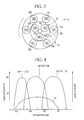
- the rotary filter 31 is provided with an inner radial portion 35 that is near the rotary shaft 31a and an outer radial portion 37 that is far from the rotary shaft 31a.
- the shifter 33 shifts the rotary filter 31 in a radial direction.
- the rotary filter 31 is shifted to an inner position in which the inner radial portion 35 is disposed in an optical path of the broad band light BB.
- the rotary filter 31 is shifted to an outer position in which the outer radial portion 37 is disposed in the optical path of the broad band light BB.
- an NR filter 40r, an NG filter 40g, an NB filter 40b are formed in its circumferential direction.
- a light shielding portion is formed between the NR filter 40r and the NG filter 40g, between the NG filter 40g and the NB filter 40b, and between the NB filter 40b and the NR filter 40r to block the broad band light BB.
- the outer radial portion 37 is provided with six filters, i.e. an NR filter 40r, an SR filter 42r, an NG filter 40g, an SG filter 42g, an NB filter 40b, and an SB filter 42b disposed in its circumferential direction.
- a light shielding portion is formed between two of the filters 40r, 42r, 40g, 42g, 40b, and 42b adjoining each other to block the broad band light BB.
- the NR filter 40r, the NG filter 40g, and the NB filter 40b transmit red band light, green band light, and blue band light, which are required for producing a normal image, respectively, out of the broad band light BB.
- the NR filter 40r transmits normal red light (NR light) having a wavelength band of 580 to 760 nm out of the broad band light BB.
- the NG filter 40g transmits normal green light (NG light) having a wavelength band of 450 to 630 nm.
- the NB filter 40b transmits normal blue light (NB light) having a wavelength band of 380 to 500 nm.
- the SR filter 42r, the SG filter 42g, and the SB filter 42b transmit red band light, green band light, and blue band light, which are required for calculating the oxygen saturation level, respectively, out of the broad band light BB.
- the SR filter 42r transmits special red light (SR light) in a wavelength band of 600 to 700 nm.
- the SG filter 42g transmits special green light (SG light) in a wavelength band of 500 to 590 nm.
- the SB filter 42b transmits special blue light (SB light) in a narrow wavelength band of 473 ⁇ 10 nm.
- the NR, NG, and NB light In the normal mode, as shown in Fig. 5A , by the rotation of the rotary filter 31 set in the inner position, the NR, NG, and NB light is applied in this order to the internal body portion. There is provided a certain light shielding period between individual applications of the light.
- the NR, NG, and NB light enters the light guide 43 through a condenser lens 38 and a rod integrator 39.
- the NR, SR, NG, SG, NB, and SB light is applied in this order to the internal body portion. There is provided a certain light shielding period between individual applications of the light.
- the NR, SR, NG, SG, NB, and SB light enters the light guide 43 through the condenser lens 38 and the rod integrator 39.
- oxyhemoglobin HbO2
- Hb deoxyhemoglobin
- the transmission wavelength bands of the SR filter 42r and the SG filter 42g may be narrowed, as with that of the SB filter 42b.
- the oxyhemoglobin (HbO2) has a higher absorption coefficient than the deoxyhemoglobin (Hb) in the transmission wavelength bands of the SR filter 42r and the SG filter 42g.
- the electronic endoscope 11 is provided with the light guide 43, a beam splitter 45, a normal imaging unit 47, and a high-sensitivity imaging unit 49.
- the light guide 43 is made of a large-diameter optical fiber, a fiber bundle, or the like.
- a lighting lens 48 for regulating a light distribution angle of the illumination light is disposed in front of each lighting window 22.
- the illumination light transmitted through the light guide 43 is applied to the internal body portion through the lighting windows 22.
- the light reflected from the body portion is incident upon an image-forming lens 51 through the imaging window 23.
- the light exits from the image-forming lens 51, and is separated into two beams by the beam splitter 45.
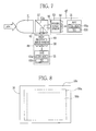
- the beam splitter 45 is composed of a prism 52, as shown in Fig. 7 .
- the prism 52 has a beam splitting surface 52a to split the incident light.
- One of the two beams split by the beam splitting surface 52a is incident upon a monochrome normal image sensor 53 of the normal imaging unit 47, while the other one is incident upon a monochrome high-sensitivity image sensor 60 of the high-sensitivity imaging unit 49.
- the image-forming lens 51, the prism 52, the normal imaging unit 47, and the high-sensitivity imaging unit 49 compose an imaging section.
- the normal imaging unit 47 includes the monochrome normal image sensor 53 and an AFE 55.
- the MPU 70 controls the operation of the normal imaging unit 47.
- the normal image sensor 53 is a FT (frame transfer), FIT (frame interline transfer), or IT (interline transfer) type CCD image sensor having a frame rate of 30 or 60 f/s, for example.
- the normal image sensor 53 has a light receiving surface 56 upon which the light is incident from the prism 52.
- the light receiving surface 56 has a matrix of pixels. Each pixel, being made of a photoelectric conversion element such as a photodiode, performs photoelectric conversion of received light and accumulates signal charge by an amount corresponding to the amount of the received light.
- the signal charge is read out on a pixel-by-pixel basis, and transmitted to the AFE 55 as an image signal.
- the rotary filter 31 necessarily has the light shielding portions in the case of using the FT type CCD image sensor, as shown in Fig. 3 , but may not have the light shielding portions in the case of using the FIT or IT type CCD image sensor.
- a Peltier element 58 is provided on the normal image sensor 53 on a side opposite to the light receiving surface 56.
- the Peltier element 58 dissipates heat produced by the normal image sensor 53 to cool the normal image sensor 53. Cooling the normal image sensor 53 contributes to reduction in dark current, which occurs in a dark area 56c of the light receiving surface 56.
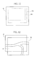
- the dark area 56c is an area that receives no reflected light, as shown in Fig. 8 .
- the ratio of output from a light receiving area 56a, which receives the reflected light, to the image signal is increased, and hence the sensitivity of the normal image sensor 53 is improved. For example, a reduction of 8°C in temperature of the normal image sensor 53 doubles the sensitivity.
- the Peltier element 58 is not necessarily provided on the normal image sensor 53.
- the AFE 55 includes a CDS-ADC 55a having a correlated double sampling circuit and an analog-to-digital converter, and a TG (timing generator) 55b.
- the CDS-ADC 55a applies correlated double sampling processing to the image signal outputted from the normal image sensor 53, to remove noise from the image signal. After the noise removal, the image signal is converted into a digital image signal of a predetermined bit number, and inputted to a DSP 72 of the processor device 13.
- the TG 55b generates a drive signal to control drive of the normal image sensor 53 such as imaging timing.
- the high-sensitivity imaging unit 49 has a monochrome high-sensitivity image sensor 60 and an AFE 55, and is driven by the MPU 70 as with the normal imaging unit 47.
- the high-sensitivity image sensor 60 has a light receiving surface 62 upon which the light is incident from the prism 52.
- the light receiving surface 62 has a matrix of pixels.
- the high-sensitivity image sensor 60 performs photoelectric conversion of received light at its light receiving surface 62, and reads out an image signal obtained thereby.
- the read image signal is transmitted to the AFE 55.
- the AFE 55 of the high-sensitivity imaging unit 49 has the same function as that of the AFE 55 of the normal imaging unit 47.
- the image signal after being processed by the AFE 55 is inputted to a DSP 73 of the processor device 13.
- the pixel of the high-sensitivity image sensor 60 is composed of an avalanche photodiode, for example.
- the high-sensitivity image sensor 60 has higher sensitivity than the normal image sensor 53 owing to an avalanche multiplication effect.
- the sensitivity of the high-sensitivity image sensor 60 is 2 to 200 times as much as that of the normal image sensor 53.
- the sensitivity ratio between the normal image sensor 53 and the high-sensitivity image sensor 60 is on the order of 1:200 at the maximum.
- the high-sensitivity image sensor 60 needs cooling to take full advantage of the avalanche multiplication effect.
- a Peltier element 58 is provided on the high-sensitivity image sensor 60 on a side opposite to the light receiving surface 62.
- the Peltier element 58 dissipates heat produced by the high-sensitivity image sensor 60 to cool the high-sensitivity image sensor 60.
- the high-sensitivity image sensor 60 that is cooled to 40°C using the Peltier element 58 has sensitivity approximately 32 times as much as the high-sensitivity image sensor 60 without being cooled.
- the high-sensitivity image sensor 60 is an FT, FIT, or IT type CCD image sensor.
- This high-sensitivity image sensor 60 operates at a frame rate lower than that of the normal image sensor 53.
- the high-sensitivity image sensor 60 may have a frame rate of 15 f/s or 7.5 f/s. Reducing the frame rate allows to elongate charge accumulation time, and hence increase the amount of light taken in the high-sensitivity image sensor 60.
- cooling the high-sensitivity image sensor 60 using the Peltier element 58 or the like can improve an S/N ratio.
- the high-sensitivity image sensor 60 has a total pixel number of "1/n 2 " and sensitivity of "n 2 ", with respect to the normal image sensor 53.
- the normal image sensor 53 and the high-sensitivity image sensor 60 may have the same or different pixel number.
- the pixels of the normal image sensor 53 and the high-sensitivity image sensor 60 may be rectangular or in another form.
- the normal image sensor 53 and the high-sensitivity image sensor 60 have the same or different aspect ratio (length-to-width ratio).
- the normal image sensor 53 and the high-sensitivity image sensor 60 have to be laid out such that an object image formed on the light receiving surface 56 of the normal image sensor 53 and an object image formed on the light receiving surface 62 of the high-sensitivity image sensor 60 become almost equal.
- an object image 57 obtained by the normal image sensor 53 partly differs from an object image 59 obtained by the high-sensitivity image sensor 60.
- An overlapping area 61 is determined by AND operation of the object images 57 and 59.
- an effective area 56b of the light receiving area 56a is referred to as an effective area 56b of the light receiving area 56a, which captures the reflected light and forms the object image 57.
- an effective area 62b of the light receiving area 62a which forms the object image 59.
- These effective areas 56b and 62b are preferably determined by checking the object image 57 outputted from the normal image sensor 53 and the object image 59 outputted from the high-sensitivity image sensor 60 on the monitor 14 after registration of the optical systems including the beam splitter 45.
- the length of the optical path of the high-sensitivity image sensor 60 may be slightly elongated because the high-sensitivity image sensor 60 does not need high sharpness.
- the processor device 12 includes the MPU 70, the DSPs 72 and 73, and a processor 75.
- the MPU 70 controls the operation of the electronic endoscope 11 and the light source device 13, in addition to the operation of the processor device 12.
- the MPU 70 has a control program memory 70a for storing various control programs and setup data.
- the control program written for observation of the oxygen saturation level is loaded from the control program memory 70a and executed to carry out various control operations.
- the control program memory 70a is rewritable.
- a control program for AFI autofluorescence imaging
- the DSP 72 obtains the image signal outputted from the normal imaging unit 47.
- the DSP 72 applies signal processing including gamma correction and white balance correction to the image signal, to produce a normal-sensor image.
- the normal-sensor image includes first and second normal-sensor images.
- the first normal-sensor image is produced from NR, NG, and NB signals obtained by the normal image sensor 53 under irradiation with the NR, NG, and NB light.
- the second normal-sensor image is produced from SR, SG, and SB signals obtained by the normal image sensor 53 under irradiation with the SR, SG, and SB light.
- the first and second normal-sensor images are transmitted to the processor 75.
- the DSP 73 performs similar processing and produces a high-sensitivity-sensor image.
- the high-sensitivity-sensor image is produced from SR, SG, and SB signals obtained by the high-sensitivity image sensor 60 under irradiation with the SR, SG, and SB light.
- the DSPs 72 and 73 apply a pixel number conversion process to the first and second normal-sensor images and the high-sensitivity-sensor image.
- the pixel number conversion process converts a pixel pitch of the first and second normal-sensor images and the high-sensitivity-sensor image by using a spline function and the like.
- the effective area 56b of the normal image sensor 53 has a pixel number of "n1 ⁇ m1”
- the effective area 62b of the high-sensitivity image sensor 60 has a pixel number of "n2 ⁇ m2”
- the pixel number of a part of every image corresponding to the effective area 56b or 62b is converted into "n ⁇ m" by the pixel number conversion process.
- nxm may be equal to "n1 ⁇ m1", “n2 ⁇ m2", or a default value.
- the aspect ratio of a pixel is preferably the same between before and after the pixel number conversion process, but may be different. Even if the aspect ratio of the pixel is different, a part of every image corresponding to the effective area 56b or 62b has the same angle of view between before and after the pixel number conversion process.
- the processor 75 includes a light amount evaluation section 78, a normal image processing section 79, and a special image processing section 80.
- the light amount evaluation section 78 measures the amount of reflected light of the SR, SG, and SB light (hereinafter collectively called "special illumination light) based on the second normal-sensor image or the high-sensitivity-sensor image. Then, the light amount evaluation section 78 judges whether or not the measured light amount is enough to calculate the oxygen saturation level, in other words, whether or not the measured light amount is not low. Out of the special illumination light, the amount of reflected light of only the SB light may be measured to judge whether or not the measured light amount is not low. In this case, the light amount is measured based on the intensity of the SB signal.
- the light amount evaluation section 78 measures the reflected light amount of the special illumination light based on an average (average pixel value) of pixel values outputted from all pixels of the entire light receiving surface 56, 62 of the normal image sensor 53 or the high-sensitivity image sensor 60, or pixels arranged in a middle portion (size of approximately 1/4) of the light receiving surface 56, 62. At this time, an amplification factor has to be taken into consideration as for the high-sensitivity-sensor image. The larger the average pixel value, the larger the reflected light amount.
- the light amount evaluation section 78 compares the average pixel value with a predetermined sensor selection threshold value, to judge whether or not the reflected light amount is not low.
- the sensor selection threshold value is preferably set at 1/50 of the maximum sensitivity of the normal image sensor 53. For example, when the maximum sensitivity is 10-bit 1024-level, the sensor selection threshold value is set at 20.
- the reflected light amount of the special illumination light may be measured from pixel values of a specific color component of the second normal-sensor image or the high-sensitivity-sensor image, e.g. an average of pixel values of a B image.
- the reflected light amount may be measured from arbitrarily weighted pixel values of a plurality of color components of the second normal-sensor image or the high-sensitivity-sensor image, e.g. by weighting at 2:2:1 the pixel values of the B image, pixel values of a G image, and pixel values of an R image.
- the normal image sensor 53 When the reflected light amount of the special illumination light is not judged to be low, only the normal image sensor 53 is used. As shown in Fig. 13A , the normal image sensor 53 sequentially captures images of the internal body portion irradiated with the NR, NG, and NB light (hereinafter collectively called "normal illumination light") and the special illumination light. The normal image sensor 53 performs imaging operation during each emission period of the normal illumination light, and readout operation in each shading period. Thus, as shown in Fig. 13B , NR, SR, NG, SG, NB, and SB signals are read out from the normal image sensor 53.
- both the normal image sensor 53 and the high-sensitivity image sensor 60 are used. As shown in Fig. 14A , the normal image sensor 53 captures images under irradiation with the normal illumination light, while the high-sensitivity image sensor 60 captures images under irradiation with the special illumination light.
- the normal image sensor 53 performs the imaging operation during each emission period of the normal illumination light, and readout operation in the shading period provided after each emission period of the normal illumination light.
- the normal image sensor 53 performs reset operation in the shading period provided after each emission period of the special illumination light, in order to discharge electric charge produced by photoelectric conversion of the special illumination light.
- the high-sensitivity image sensor 60 performs the imaging operation during each emission period of the special illumination light, and the readout operation in the shading period provided after each emission period of the special illumination light.
- the high-sensitivity image sensor 60 performs the reset operation in the shading period provided after each emission period of the normal illumination light, in order to discharge electric charge produced by photoelectric conversion of the normal illumination light.
- the NR, NG, and NB signals are read out from the normal image sensor 53, while the SR, SG, and SB signals are read out from the high-sensitivity image sensor 60.
- the light amount evaluation section 78 may determine which sensor to use based on two sensor selection threshold values.
- first and second sensor selection threshold values are set in advance.
- the second sensor selection threshold value is larger than the first sensor selection threshold value.
- the second sensor selection threshold value is set at 1/25 of the maximum sensitivity, while the first sensor selection threshold value is set at 1/50 of the maximum sensitivity.
- the average pixel value of the second normal-sensor image is the first sensor selection threshold value or less, the use of the high-sensitivity image sensor 60 is started.
- the high-sensitivity image sensor 60 captures the images under irradiation with the special illumination light, while the normal image sensor 53 captures the images under irradiation with the normal illumination light.
- the normal image sensor 53 captures the images under irradiation with the normal and special illumination light.
- a binning process may be applied to further sensitize the image signal obtained by the high-sensitivity image sensor 60.
- a binning processor 70b of the MPU 70 controls the high-sensitivity image sensor 60.
- hardware binning is adopted in which pixel addition is performed within the high-sensitivity image sensor 60, but software binning may be adopted instead in which outputted signals are subjected to the pixel addition.
- a drive signal for driving the high-sensitivity image sensor 60 is modified.
- the pixel area obtained by the pixel addition does not necessarily have the same number of pixels between its length and width directions. For example, the pixel area may have two pixels in the length direction and one pixel in the width direction, or four pixels in the length direction and one pixel in the width direction.
- the light amount evaluation section 78 has a binning start threshold value and a binning stop threshold value.
- the binning stop threshold value is preferably larger than the binning start threshold value.
- the binning stop threshold value is set at "(binning start threshold value) ⁇ 16+10". If the difference between the binning start and stop threshold values is small, switching between performing and not performing the binning process occurs too often. Thus, it is preferable that the binning start and stop threshold values are set so as to keep an appropriate switching frequency.
- the image signal is read out in a read unit of 1 ⁇ 1 pixel without performing the binning process, as long as the average pixel value of the high-sensitivity-sensor image obtained by the high-sensitivity image sensor 60 is the binning start threshold value or more.
- the binning process is started, and the image signal is read out in a read unit of 4x4 pixels, for example.
- the binning process is continued as long as the average pixel value of the high-sensitivity-sensor image is less than the binning stop threshold value.
- the average pixel value is the binning stop threshold value or more, the binning process is stopped, and the image signal is read out in the read unit of 1 ⁇ 1 pixel without performing the binning process.
- the level of the binning process in other words, the number of lengthwise and widthwise pixels being the read unit of the image signal is arbitrary changeable in accordance with the average pixel value of the high-sensitivity-sensor image. More specifically, the smaller the average pixel value, the larger the level of the binning process is set. For example, when the average pixel value is less than 1/25 of the maximum sensitivity, the binning process is performed in a read unit of 2 ⁇ 2 pixels. When the average pixel value is further reduced to less than 1/50, the binning process is performed in a read unit of 4x4 pixels.
- the use of only the normal image sensor 53 may be switched to the use of the high-sensitivity image sensor 60, and furthermore the absence of the binning process may be switched to the presence of the binning process in accordance with reduction in the reflected light amount of the special illumination light.
- Figs. 13A, 13B , 14A, and 14B show imaging operation using the FT type image sensor, in which the shading period for electric charge transfer is necessarily provided between the adjacent emission periods of the illumination light.
- the shading period is unnecessary.
- Fig. 13C corresponding to Fig. 13A
- Fig. 14C shows the imaging operation in a case where the reflected light amount of the special illumination light is low.
- the normal image processing section 79 assigns the B, G, and R images of the first normal-sensor image outputted from the DSP 72 to B, G, and R channels of the monitor 14, respectively, so the normal image is displayed on the monitor 14. Since the B, G, and R images of the first normal-sensor image are captured at different times, these images are preferably registered with each other by pattern matching or the like.
- the special image processing section 80 includes a position register 81, an intensity ratio calculator 82, a correlation memory 83, an oxygen saturation level calculator 84, and a special image generator 85.
- the position register 81 performs positional registration among the B, G, and R images of the second normal-sensor image obtained by the normal image sensor 53 or the high-sensitivity-sensor image obtained by the high-sensitivity image sensor 60. In the positional registration, a matching process is preferably performed so that a blood vessel pattern of the B, G, and R images coincides with each other.
- the intensity ratio calculator 82 calculates an intensity ratio B/G between the B and G images of the second normal-sensor image or the high-sensitivity-sensor image and an intensity ratio R/G between the G and R images thereof.
- the intensity ratio calculator 82 calculates the intensity ratios B/G and R/G on a pixel-by-pixel basis by using the intensity of the pixel situated in the same position in the B and G images and in the R and G images.
- the intensity ratios are calculated as to every pixel included in the image signal, but may be calculated as to only pixels situated in a blood vessel area. In this case, the blood vessel area is determined based on difference in the pixel value between the blood vessel area and the other area.
- the correlation memory 83 stores the correlation among the intensity ratios B/G and R/G and the oxygen saturation level.
- the correlation takes the form of a two-dimensional table in which contour lines representing the oxygen saturation level are defined in two-dimensional space.
- the position and shape of the contour lines are determined by physical simulation of light scattering, and variable in accordance with blood volume. For example, variation in the blood volume widens or narrows the distance between the contour lines next to each other.
- the intensity ratios B/G and R/G are stored in log scale.
- the correlation is closely related to the light absorption property of oxyhemoglobin HbO and deoxyhemoglobin Hb (see Fig. 6 ) and the light scattering property of mucosa.
- the use of a wavelength of 473 nm at which the absorption coefficient much differs between oxyhemoglobin HbO and deoxyhemoglobin Hb allows the obtainment of information about the oxygen saturation level.
- the B image including a wavelength component of 473 nm is highly dependent not only on the oxygen saturation level but also on the blood volume.
- the use of the R image, which corresponds to light mainly dependent on the blood volume, and the G image, which is a reference image (standardization signal) of the B and R images, in addition to the B image, allows the obtainment of the oxygen saturation level with high accuracy with eliminating the influence of the blood volume.
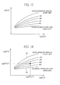
- the intensity ratio B/G increases with increase in the intensity ratio R/G.
- the contour line representing an oxygen saturation level of 0% ascends slantly.
- the reason for this is as follows.
- the blood volume increases with increase in the intensity ratio R/G due to the correlation therebetween.
- a signal value of the G image decreases most greatly with increase in the blood volume, and a signal value of the B image decreases next greatly. This is because the absorption coefficient is higher at a wavelength band of 540 to 580 nm included in the G image than that at a wavelength band of around 470 nm included in the B image (see Fig. 6 ).
- an intensity value of G being a denominator decreases more greatly than that of the B being a numerator.
- the intensity ratio B/G increases with increase in the blood volume.
- the oxygen saturation level calculator 84 calculates the oxygen saturation level of each pixel with the use of the correlation stored in the correlation memory 83 and the intensity ratios B/G and R/G obtained by the intensity ratio calculator 82.
- the intensity ratio calculator 82 calculates intensity ratios B*/G* and R*/G*.
- a point P corresponding to the signal ratios B*/G* and R*/G* is determined in the correlation stored in the correlation memory 83.
- the point P indicates the percentile of the oxygen saturation level.
- the point P is positioned in a contour line of 60%, so the oxygen saturation level is 60%.
- the oxygen saturation level is determined to be 0%. If the point is positioned below the upper limit line 88, the oxygen saturation level is determined to be 100%. Note that, if the point is out of the range between the lower limit line 87 and the upper limit line 88, the oxygen saturation level of the point may be judged to be unreliable and not be displayed on the monitor 14.
- the special image generator 85 produces the special image based on the oxygen saturation level obtained by the oxygen saturation level calculator 84.
- the special image may be a whole artificial color image in which the entire normal image is colored with artificial colors in accordance with the degree of the oxygen saturation level, or a partly artificial color image in which only a hypoxic region having the oxygen saturation level less than a certain value is colored artificially while the other region colored normally.
- the produced special image is displayed on the monitor 14.
- a normal image 90 and a special image 91 may be displayed concurrently side-by-side on the monitor 14 as shown in Fig. 19A , or may be displayed alternately on the monitor 14 as shown in Fig. 19B .
- the NR, SR, NG, SG, NB, and SB light is applied in this order in the special mode, but the order is not limited to this.
- the NR, NG, and NB light may be applied first, and then the SR, SG, and SB light may be applied.
- a threshold value that is used for commanding the normal image sensor 53 to start the binning process is preferably set higher than the above binning start threshold value (the threshold value used for commanding the high-sensitivity image sensor 60 to start the binning process).
- the CCD image sensors are used in the normal imaging unit 47 and the high-sensitivity imaging unit 49 in the above embodiment, but CMOS image sensors may be used in a like manner.
- the NG and NR light is used instead of the SG and SR light of the first embodiment, as illumination light necessary for producing the special image.
- the other configuration is the same as that of the first embodiment, so only difference from the first embodiment will be described below.
- a rotary filter 200 having an inner radial portion 201 and an outer radial portion 202, is shifted in the normal mode to the inner position in which the inner radial portion 201 is disposed in the optical path of the broad band light BB.
- the rotary filter 200 is shifted to the outer position in which the outer radial portion 202 is disposed in the optical path of the broad band light BB.
- the inner radial portion 201 has the same structure as the inner radial portion 35 of the rotary filter 31 of the first embodiment. Note that, the rotary filter 200 having the light shielding portions is necessary used in the case of using the FT type CCD image sensor, but another rotary filter without having the light shielding portions is adoptable in the case of using the FIT or IT type image sensor.
- the outer radial portion 202 which has different structure from that of the outer radial portion 37 of the rotary filter 31 of the first embodiment, does not have the SR filter 42r and the SG filter 42g.
- the outer radial portion 202 is formed with four filters i.e. the NR filter 40r, the NG filter 40g, the NB filter 40b, and the SB filter 42b arranged in its circumferential direction.
- the light shielding portion is formed between two of the filters 40r, 40g, 40b, and 42b adjoining each other to block the broad band light BB.
- the rotation of the rotary filter 200 set in the outer position allows the emission of the NR, NG, NB, and SB light in this order to the internal body portion.
- the shading period is provided after each emission period.
- the DSP 72 produces the first normal-sensor image from the NR, NG, and NB signals inputted from the AFE 55 of the normal imaging unit 47.
- the DSP 72 produces the second normal-sensor image from the NR, NG, SB signals inputted from the AFE 55 of the normal imaging unit 47.
- the AFE 55 of the normal imaging unit 47 inputs the imaging signals not only to the DSP 72 but also to the DSP 73.
- the DSP 73 produces the high-sensitivity-sensor image from the NR and NG signals inputted from the AFE 55 of the normal imaging unit 47 and the SB signal inputted from the AFE 55 of the high-sensitivity imaging unit 49.
- the light amount evaluation section 78 of the second embodiment measures the reflected light amount of the SB light based on the B image of the second normal sensor image or the high-sensitivity-sensor image.
- the light amount evaluation section 78 judges whether or not the reflected light amount of the SB light is enough to reliably calculate the oxygen saturation level, in other words, is not low.
- the binning process is performed as follows in the second embodiment. As shown in Fig. 23 , the light amount evaluation section 78 calculates the average pixel value based on the high-sensitivity-sensor image obtained under irradiation with the SB light. The start and stop of the binning process are controlled in a like manner as the first embodiment by comparing the average pixel value with the binning start and stop threshold values.
- the high-sensitivity image sensor 60 when the high-sensitivity image sensor 60 performs the binning process, it is necessary to equalize the pixel number of the NR and NG signals outputted from the normal image sensor 53 with the pixel number of the SB signal outputted from the high-sensitivity image sensor 60. This is because not only the SB signal but also the NR and NG signals are used to produce the special image.
- the equalization of the pixel number among the NR, NG, and SB signals allows close agreement between an image of an object produced by the NR and NG signals and an image of the object produced by the SB signal.
- a display area of the NR and NG signals coincides with a display area of the SB signal.
- the pixel number of the NR and NG signals when the pixel number of the NR and NG signals is represented by "N", the pixel number of the SB signal after being subjected to the binning process in a unit of 2 ⁇ 2 pixels becomes "N/4". At this time, the pixel number of the SB signal is multiplied by 4 by a pixel number increasing process, or the pixel number of the NR and NG signals is multiplied by 1/4 by a pixel number decreasing process, in order to equalize the pixel number of the NR, NG, and SB signals.
- the special image is produced from the NR, NG, and SB signals having the same pixel number.
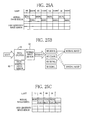
- the switching between the normal image sensor 53 and the high-sensitivity image sensor 60 is performed as follows. As shown in Fig. 25A , the normal image sensor 53 captures the image of the internal body portion irradiated with the SB light, as long as the reflected light amount of the SB light is not judged to be low. Thus, the NR, NG, NB, and SB signals are read out in this order from the normal image sensor 53.
- the high-sensitivity image sensor 60 captures the image under irradiation with the SB light.
- the normal image sensor 53 performs the imaging operation during each emission period of the NR, NG, and NB light, and readout operation in the shading period provided after each emission period.
- the normal image sensor 53 performs reset operation in the shading period provided after the emission period of the SB light, in order to discharge electric charge produced by photoelectric conversion of the SB light.
- the high-sensitivity image sensor 60 performs the imaging operation only during the emission period of the SB light, and the readout operation of the SB signal in the shading period provided after the emission period of the SB light.
- the high-sensitivity image sensor 60 performs the reset operation in the shading period provided after the emission period of the NB light, in order to discharge electric charge produced by photoelectric conversion of the NR, NG, and NB light.
- the NR, NG, and NB signals are read out from the normal image sensor 53, while the SB signal is read out from the high-sensitivity image sensor 60.
- the normal image is produced from the NR, NG, and NB signals.
- the special image is produced from the NR, NG, and SB signals.
- a method for producing the normal image and the special image is the same as that of the first embodiment.
- Figs. 25A, 25B , 26A, and 26B show imaging operation using the FT type image sensor, in which the shading period for electric charge transfer is necessarily provided between the adjacent emission periods of the illumination light.
- the shading period is unnecessary.
- Fig. 25C corresponding to Fig. 25A
- Fig. 26C shows the imaging operation in a case where the reflected light amount of the SB light is low.
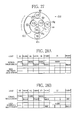
- another rotary filter 210 having a large SB filter 42b may be used instead of the rotary filter 200.
- the use of the rotary filter 210 makes the emission period of the SB light longer than the emission periods of the other NR, NG, and NB light. Thus, the image is captured with higher sensitivity during the emission period of the SB light.
- the rotary filter 210 having the shielding portions, as shown in Fig. 27 is necessarily used in the case of adopting the FT type CCD image sensor, but a rotary filter without having the shielding portion is usable in the case of adopting the FIT or IT type image sensor.
- either of the normal image sensor 53 and the high-sensitivity image sensor 60 performs the imaging operation under irradiation with the SB light for longer time than time of the imaging operation under irradiation with the NR, NG, and NB light.
- Figs. 28A and 28B show the imaging operation using the FT type image sensor, in which the shading period for electric charge transfer is necessarily provided between the adjacent emission periods of the illumination light.
- the shading period is unnecessary.
- Figs. 28A and 28C show the imaging operation in a case where the reflected light amount of the SB light is not low.
- Figs. 28B and 28D show the imaging operation in a case where the reflected light amount of the SB light is low.
- the NR, NG, NB, and SB light is emitted in this order in the special mode, but the order is not limited to this.
- exposure time of the high-sensitivity image sensor 60 is extended in order to increase the sensitivity of the image signals used for producing the special image.
- a shutter 95 is provided between the beam splitter 45 and the high-sensitivity image sensor 60 to control the exposure time. The operation of the shutter 95 is controlled by an exposure time controller 70c of the MPU 70.
- the following description describes exposure time control in the case of producing the special image from the SR, SG, and SB signals (refer to the first embodiment), but exposure time control in the case of producing the special image from the NR, NG, and SB signals (refer to the second embodiment) can be performed in a like manner.
- the third embodiment is the same as or similar to the first and second embodiments except for the binning process, so the description of the same configuration as those of the first and second embodiments will be omitted.
- the light amount evaluation section 78 of the processor 75 calculates the average pixel value based on the high-sensitivity-sensor image (image produced from the SR, SG, and SB signals).
- the average pixel value is compared with an extension start threshold value or an extension stop threshold value set in advance.
- the extension stop threshold value is preferably set larger than the extension start threshold value. For example, the extension stop threshold value is four times as large as the extension start threshold value.
- the exposure time is set at 1/30 seconds. This exposure time (1/30 seconds) is maintained, as long as the average pixel value of the high-sensitivity-sensor image is larger than the extension start threshold value.
- the exposure time is extended from 1/30 seconds to 1/7.5 seconds by control of the shutter 95. In other words, the extension of the exposure time is started.
- the exposure time is set at 1/7. 5 seconds. This exposure time (1/7.5 seconds) is maintained, as long as the average pixel value is less than the extension stop threshold value.
- the exposure time is returned to 1/30 seconds. How much the exposure time is to be extended is arbitrarily changeable in accordance with the average pixel value of the high-sensitivity-sensor image.
- the use of only the normal image sensor 53 may be switched to the use of the high-sensitivity image sensor 60 and furthermore to the extension of the exposure time in accordance with reduction in the reflected light amount of the special illumination light.
- the use of only the normal image sensor 53 may be switched to the use of the high-sensitivity image sensor 60, to the use of one of the extension of the exposure time and the start of the binning process, and furthermore to the use of both of the extension of the exposure time and the start of the binning process in accordance with reduction in the reflected light amount of the special illumination light.
- the exposure time is extended in the high-sensitivity image sensor 60, but the extension of the exposure time may be performed in the normal image sensor 53 in the case of producing the special image from the SR, SG, and SB signals outputted from the normal image sensor 53.
- a shutter 95 is provided between the beam splitter 45 and the normal image sensor 53, and the extension of the exposure time is performed only when the SB light is incident thereon.
- a threshold value that is used for starting the extension of the exposure time in the normal image sensor 53 is preferably set higher than the extension start threshold value described above.
- any one of the extension of the exposure time and the binning process may be selectively carried out.
- one of the binning process and the extension of the exposure time is selected in accordance with object distance (near view or far view).
- the extension of the exposure time is preferably selected instead of the binning process, which causes reduction of resolution.
- the binning process is preferably performed.
- the illumination light is produced using the light source device 13 having the rotary filter.
- a light source device 100 that is constituted of laser beam sources LD1 and LD2, a phosphor 98, and a source controller 102 for controlling the operation of laser beam sources LD1 and LD2 may be used to produce the illumination light.
- a normal imaging unit 130 that is provided with a simultaneous type color normal image sensor 110 having RGB color filters is used instead of the monochrome normal image sensor 53.
- a high-sensitivity imaging unit 131 that is provided with a simultaneous type color high-sensitivity image sensor 112 having RGB color filters is used instead of the monochrome high-sensitivity image sensor 60.
- the color normal image sensor 110 and the color high-sensitivity image sensor 112 are IT (inter transfer) type image sensors having an electronic shutter.
- the laser beam source LD1 emits a laser beam N1 having a wavelength of 440 ⁇ 10 nm.
- the laser beam source LD2 emits a laser beam N2 having a wavelength of 470 ⁇ 10 nm.
- As the laser beam sources LD1 and LD2, InGaN, InGaNAs, or GaNAs laser diodes are available.
- the laser beams N1 and N2 are led to a combiner 106 through optical fibers 104.
- the combiner 106 being an optical element having the function of combining light beams transmitted through the optical fibers 104, combines optical axes of light beams that are incident selectively from the optical fibers 104 into one.
- the phosphor 98 is disposed downstream from the combiner 106.
- LEDs light emitting diodes
- the phosphor 98 is excited by the laser beam N1, and emits fluorescence FL1 having a wavelength band ranging from the green region to the red region. Mixture of the fluorescence FL1 and the laser beam N1 transmitted through the fluorescence 98 produces normal illumination light. Also, the phosphor 98 is excited by the laser beam N2, and emits fluorescence FL2 having a wavelength band ranging from the green region to the red region. The fluorescence FL2 has slightly less intensity than the fluorescence FL1. Mixture of the fluorescence FL2 and the laser beam N2 transmitted through the phosphor 98 produces special illumination light.
- the type of the phosphor 98 is not specifically limited, as long as the phosphor is excited by blue excitation light and emits fluorescence having a wavelength band ranging from the green region to the red region. For example, microwhite (trademark) is available.
- the source controller 102 turns on only the laser beam source LD1, so the normal illumination light is applied to the internal body portion, as shown in Fig. 33A .
- the source controller 102 alternately turns on and off the laser beam sources LD1 and LD2, so the normal illumination light and the special illumination light is applied alternately, as shown in Fig. 33B .
- the normal and special illumination light enters the light guide 43 through the condenser lens 38 and the rod integrator 39.
- the normal imaging unit 130 and the high-sensitivity imaging unit 131 with the use of the light source device 100 will be hereinafter described.
- the normal image sensor 110 captures images of the internal body portion irradiated with the normal illumination light and the special illumination light.
- the normal image sensor 110 performs imaging operation and readout operation of an image signal in each emission period of the normal and special illumination light.
- the electronic shutter in a period between the emission period of the normal illumination light and the emission period of the special illumination light, the electronic shutter is actuated to discharge (reset) electric charge accumulated in the normal image sensor 110.
- the normal image sensor 110 outputs NR, NG, and NB signals in the emission period of the normal illumination light, and SR, SG, and SB signals in the emission period of the special illumination light.
- the normal image sensor 110 When the reflected light amount of the special illumination light is low, as shown in Fig. 35A , not only the normal image sensor 110 but also the high-sensitivity image sensor 112 is used. While the normal image sensor 110 captures the images under irradiation with the normal illumination light, the high-sensitivity image sensor 112 captures the images under irradiation with the special illumination light. The normal image sensor 110 performs the imaging operation and the readout operation in the emission period of the normal illumination light. The high-sensitivity image sensor 112 performs the imaging operation and the readout operation in the emission period of the special illumination light. Therefore, as shown in Fig. 35B , the normal image sensor 110 outputs the NR, NG, and NB signals, and the high-sensitivity image sensor 112 outputs the SR, SG, and SB signals.
- the normal and special illumination light is produced by mixture of the fluorescence and the blue laser beam in the light source device 100.
- the normal and special illumination light may be produced by mixture of white light from a xenon lamp or the like and a laser beam, or mixture of white light and LED light.
- the SB light having a wavelength of 473 nm is used to produce the special image, but illumination light having another wavelength may be used instead.
- illumination light having another wavelength may be used instead.
- a transmission wavelength band for example, 500 to 630 nm
- the wavelength for example, 560 ⁇ 10 nm
- the oxygen saturation level independent from the blood volume is calculated using the SB signal having a narrow band component of 473 nm, the SG signal having a green broad band component, and the SR signal having a red broad band component.
- the oxygen saturation level independent from the depth of the blood vessel may be calculated using a first SB signal having a narrow band component of 445 nm, a second SB signal having a narrow band component of 473 nm, and a third SB signal having a narrow band component of 405 nm.
- the SG filter 42g provided in the outer radial portion 37 of the rotary filter 31 is replaced with a filter transmitting narrow band light of 445 ⁇ 10 nm
- the SR filter 42r is replaced with a filter transmitting narrow band light of 405 ⁇ 10 nm.
- a luminance coordinate system 120 is an XY coordinate system having two axes of X and Y.
- a first intensity ratio S1/S3 between the first and third SB signals is assigned to the X axis.
- a second intensity ratio S2/S3 between the second and third SB signals is assigned to the Y axis.
- a blood information coordinate system 121 provided on the luminance coordinate system 120 is a UV coordinate system having two axes of U and V.
- the depth D of the blood vessel is assigned to the U axis.
- the oxygen saturation level StO2 is assigned to the V axis.
- the U axis has a positive gradient to the luminance coordinate system 120.
- an upper right direction indicates that the blood vessel is superficial, while a lower left direction indicates that the blood vessel is deep.
- the V axis has a negative gradient to the luminance coordinate system 120.
- an upper left direction indicates that the oxygen saturation level StO2 is low, while a lower right direction indicates that the oxygen saturation level StO2 is high.
- the U and V axes intersect with each other at right angles at an intersection point P.
- the first intensity ratio S1*/S3* between the first and third SB signals obtained by imaging the body portion, and the second intensity ratio S2*/S3* between the second and third SB signals are calculated.
- coordinates Q (X*, Y*) corresponding to the first and second intensity ratios S1*/S3* and S2*/S3* are plotted on the luminance coordinate system 120.
- the coordinates Q are projected to each of the V axis representing the oxygen saturation level and the U axis representing the depth of the blood vessel, so the coordinates Q (U*, V*) are determined. Accordingly, "U*" being blood vessel depth information and "V*" being oxygen saturation level information of one pixel are obtained.
- Such a process is performed in order to obtain the blood vessel depth information and the oxygen saturation level information of all the pixels in a screen.
- the special image is produced based on the obtained oxygen saturation level information.
Landscapes
- Health & Medical Sciences (AREA)
- Life Sciences & Earth Sciences (AREA)
- Surgery (AREA)
- Physics & Mathematics (AREA)
- Engineering & Computer Science (AREA)
- Biophysics (AREA)
- Veterinary Medicine (AREA)
- Optics & Photonics (AREA)
- Pathology (AREA)
- Public Health (AREA)
- General Health & Medical Sciences (AREA)
- Biomedical Technology (AREA)
- Heart & Thoracic Surgery (AREA)
- Medical Informatics (AREA)
- Molecular Biology (AREA)
- Animal Behavior & Ethology (AREA)
- Radiology & Medical Imaging (AREA)
- Nuclear Medicine, Radiotherapy & Molecular Imaging (AREA)
- Spectroscopy & Molecular Physics (AREA)
- Signal Processing (AREA)
- Endoscopes (AREA)
- Measurement Of The Respiration, Hearing Ability, Form, And Blood Characteristics Of Living Organisms (AREA)
Applications Claiming Priority (1)
| Application Number | Priority Date | Filing Date | Title |
|---|---|---|---|
| JP2012152641A JP5623469B2 (ja) | 2012-07-06 | 2012-07-06 | 内視鏡システム、内視鏡システムのプロセッサ装置、及び内視鏡用制御プログラム |
Publications (2)
| Publication Number | Publication Date |
|---|---|
| EP2682044A1 true EP2682044A1 (de) | 2014-01-08 |
| EP2682044B1 EP2682044B1 (de) | 2017-11-15 |
Family
ID=48790206
Family Applications (1)
| Application Number | Title | Priority Date | Filing Date |
|---|---|---|---|
| EP13175345.1A Not-in-force EP2682044B1 (de) | 2012-07-06 | 2013-07-05 | Endoskopsystem und prozessorvorrichtung zur steuerung des endoskopsystems |
Country Status (3)
| Country | Link |
|---|---|
| US (1) | US10016152B2 (de) |
| EP (1) | EP2682044B1 (de) |
| JP (1) | JP5623469B2 (de) |
Cited By (2)
| Publication number | Priority date | Publication date | Assignee | Title |
|---|---|---|---|---|
| WO2015142799A1 (en) * | 2014-03-17 | 2015-09-24 | Intuitive Surgical Operations, Inc. | System and method for tissue contact detection and for auto-exposure and illumination control |
| EP4445827A4 (de) * | 2022-01-07 | 2025-04-09 | FUJIFILM Corporation | Prozessorvorrichtung, betriebsverfahren dafür und endoskopsystem |
Families Citing this family (14)
| Publication number | Priority date | Publication date | Assignee | Title |
|---|---|---|---|---|
| US10188411B2 (en) | 2013-04-16 | 2019-01-29 | Calcula Technologies, Inc. | Everting balloon for medical devices |
| US9232956B2 (en) | 2013-04-16 | 2016-01-12 | Calcula Technologies, Inc. | Device for removing kidney stones |
| US10219864B2 (en) | 2013-04-16 | 2019-03-05 | Calcula Technologies, Inc. | Basket and everting balloon with simplified design and control |
| CN105324064B (zh) * | 2013-05-30 | 2017-10-27 | Hoya株式会社 | 生成示出生物组织中生物物质浓度分布图像的方法和装置 |
| WO2015146972A1 (ja) * | 2014-03-28 | 2015-10-01 | 富士フイルム株式会社 | 内視鏡システム、内視鏡システムのプロセッサ装置、及び内視鏡システムの作動方法 |
| US20150305602A1 (en) * | 2014-04-23 | 2015-10-29 | Calcula Technologies, Inc. | Integrated medical imaging system |
| JP6204314B2 (ja) * | 2014-09-03 | 2017-09-27 | Hoya株式会社 | 電子内視鏡システム |
| JP6214823B2 (ja) * | 2015-10-14 | 2017-10-18 | オリンパス株式会社 | 内視鏡用光源装置及び内視鏡システム |
| US9963630B2 (en) | 2015-11-18 | 2018-05-08 | Cnpc Usa Corporation | Method for a fracturing fluid system at high temperatures |
| JP2017123997A (ja) * | 2016-01-13 | 2017-07-20 | オリンパス株式会社 | 撮像システムおよび処理装置 |
| EP3424403B1 (de) * | 2016-03-03 | 2024-04-24 | Sony Group Corporation | Vorrichtung, system, verfahren und programm zur verarbeitung medizinischer bilder |
| JP6654117B2 (ja) * | 2016-08-31 | 2020-02-26 | 富士フイルム株式会社 | 内視鏡システム及び内視鏡システムの作動方法 |
| JP2020062063A (ja) * | 2017-03-31 | 2020-04-23 | 国立大学法人九州大学 | ヘモグロビン定量装置、ヘモグロビン定量方法及びヘモグロビン定量プログラム |
| JP7405080B2 (ja) * | 2018-08-13 | 2023-12-26 | ソニーグループ株式会社 | 医療用システム、医療用光源装置及び医療用光源装置の作動方法 |
Citations (5)
| Publication number | Priority date | Publication date | Assignee | Title |
|---|---|---|---|---|
| US5827190A (en) * | 1994-03-28 | 1998-10-27 | Xillix Technologies Corp. | Endoscope having an integrated CCD sensor |
| US20030189663A1 (en) * | 2002-04-04 | 2003-10-09 | Richard Wolf Gmbh | Solid-state video camera and method for brightness control |
| EP2020202A2 (de) * | 2007-07-31 | 2009-02-04 | Olympus Medical Systems Corp. | Medizinisches Gerät |
| US20100245551A1 (en) * | 2009-03-26 | 2010-09-30 | Olympus Corporation | Image processing device, computer-readable storage medium, and image processing method |
| EP2446809A1 (de) * | 2010-10-26 | 2012-05-02 | Fujifilm Corporation | Elektronisches Endoskopsystem mit Prozessorvorrichtung und Verfahren zur Verarbeitung endoskopischer Bilder |
Family Cites Families (17)
| Publication number | Priority date | Publication date | Assignee | Title |
|---|---|---|---|---|
| JP4315489B2 (ja) * | 1998-07-31 | 2009-08-19 | オリンパス株式会社 | 内視鏡装置 |
| JP4321697B2 (ja) * | 2000-08-02 | 2009-08-26 | 富士フイルム株式会社 | 蛍光画像表示方法および装置 |
| JP4095330B2 (ja) * | 2002-04-17 | 2008-06-04 | ペンタックス株式会社 | 自動調光機能を備えた電子内視鏡装置 |
| DE10224756B4 (de) * | 2002-06-04 | 2009-07-30 | Siemens Ag | Verfahren und Vorrichtung zur Erzeugung einer kombinierten Parameterkarte |
| JP4315748B2 (ja) * | 2003-07-07 | 2009-08-19 | オリンパス株式会社 | 内視鏡装置 |
| JP2005348902A (ja) * | 2004-06-09 | 2005-12-22 | Olympus Corp | 内視鏡装置 |
| JP4545503B2 (ja) | 2004-07-14 | 2010-09-15 | オリンパス株式会社 | 画像生成装置およびその方法 |
| JP4391998B2 (ja) * | 2006-03-07 | 2009-12-24 | オリンパス株式会社 | 内視鏡装置 |
| ES2560180T3 (es) * | 2006-06-28 | 2016-02-17 | Medtronic Ardian Luxembourg S.à.r.l. | Sistemas para la neuromodulación renal inducida térmicamente |
| JP2008043742A (ja) * | 2006-07-20 | 2008-02-28 | Pentax Corp | 電子内視鏡システム |
| US7973820B2 (en) * | 2007-05-17 | 2011-07-05 | Panasonic Corporation | Motion detector and image capture device, interchangeable lens and camera system including the motion detector |
| DE102007026337B4 (de) * | 2007-06-06 | 2016-11-03 | Arnold & Richter Cine Technik Gmbh & Co. Betriebs Kg | Digitale Kamera |
| US20100149393A1 (en) * | 2008-05-22 | 2010-06-17 | Panavision Imaging, Llc | Increasing the resolution of color sub-pixel arrays |
| JP5389742B2 (ja) * | 2009-09-30 | 2014-01-15 | 富士フイルム株式会社 | 電子内視鏡システム、電子内視鏡用のプロセッサ装置、及び電子内視鏡システムの作動方法 |
| JP5356191B2 (ja) * | 2009-11-26 | 2013-12-04 | オリンパス株式会社 | 蛍光観察装置 |
| JP5113139B2 (ja) | 2009-11-26 | 2013-01-09 | 東芝ホームテクノ株式会社 | 電気湯沸かし器 |
| JP2012016545A (ja) * | 2010-07-09 | 2012-01-26 | Fujifilm Corp | 内視鏡装置 |
-
2012
- 2012-07-06 JP JP2012152641A patent/JP5623469B2/ja active Active
-
2013
- 2013-07-03 US US13/934,476 patent/US10016152B2/en active Active
- 2013-07-05 EP EP13175345.1A patent/EP2682044B1/de not_active Not-in-force
Patent Citations (5)
| Publication number | Priority date | Publication date | Assignee | Title |
|---|---|---|---|---|
| US5827190A (en) * | 1994-03-28 | 1998-10-27 | Xillix Technologies Corp. | Endoscope having an integrated CCD sensor |
| US20030189663A1 (en) * | 2002-04-04 | 2003-10-09 | Richard Wolf Gmbh | Solid-state video camera and method for brightness control |
| EP2020202A2 (de) * | 2007-07-31 | 2009-02-04 | Olympus Medical Systems Corp. | Medizinisches Gerät |
| US20100245551A1 (en) * | 2009-03-26 | 2010-09-30 | Olympus Corporation | Image processing device, computer-readable storage medium, and image processing method |
| EP2446809A1 (de) * | 2010-10-26 | 2012-05-02 | Fujifilm Corporation | Elektronisches Endoskopsystem mit Prozessorvorrichtung und Verfahren zur Verarbeitung endoskopischer Bilder |
Cited By (5)
| Publication number | Priority date | Publication date | Assignee | Title |
|---|---|---|---|---|
| WO2015142799A1 (en) * | 2014-03-17 | 2015-09-24 | Intuitive Surgical Operations, Inc. | System and method for tissue contact detection and for auto-exposure and illumination control |
| JP2017510348A (ja) * | 2014-03-17 | 2017-04-13 | インテュイティブ サージカル オペレーションズ, インコーポレイテッド | 組織接触検出のための、並びに自動露出及び照明制御のためのシステム及び方法 |
| US10512512B2 (en) | 2014-03-17 | 2019-12-24 | Intuitive Surgical Operations, Inc. | System and method for tissue contact detection and for auto-exposure and illumination control |
| US11331156B2 (en) | 2014-03-17 | 2022-05-17 | Intuitive Surgical Operations, Inc. | System and method for tissue contact detection and for auto-exposure and illumination control |
| EP4445827A4 (de) * | 2022-01-07 | 2025-04-09 | FUJIFILM Corporation | Prozessorvorrichtung, betriebsverfahren dafür und endoskopsystem |
Also Published As
| Publication number | Publication date |
|---|---|
| JP2014014438A (ja) | 2014-01-30 |
| JP5623469B2 (ja) | 2014-11-12 |
| EP2682044B1 (de) | 2017-11-15 |
| US20140012113A1 (en) | 2014-01-09 |
| US10016152B2 (en) | 2018-07-10 |
Similar Documents
| Publication | Publication Date | Title |
|---|---|---|
| EP2682044B1 (de) | Endoskopsystem und prozessorvorrichtung zur steuerung des endoskopsystems | |
| EP2682045B1 (de) | Endoskopsystem, Prozessorvorrichtung dafür und Verfahren zur Steuerung des Endoskopsystems | |
| EP2301415B1 (de) | Endoskop zur simultanen schmalbandigen und Weisslichtbeobachtung | |
| US9918613B2 (en) | Endoscope system and operating method thereof | |
| EP2301416B1 (de) | Verfahren zur Steuerung eines Endoskops und Endoskop | |
| JP5303012B2 (ja) | 内視鏡システム、内視鏡システムのプロセッサ装置及び内視鏡システムの作動方法 | |
| EP3117757B1 (de) | Endoskopsystem | |
| US9345392B2 (en) | Endoscope system and method for imaging exposure control | |
| JP6791821B2 (ja) | 内視鏡システム | |
| US20130245411A1 (en) | Endoscope system, processor device thereof, and exposure control method | |
| WO2007010709A1 (ja) | 内視鏡及び内視鏡装置 | |
| EP2505121B1 (de) | Endoskopvorrichtung | |
| JP5539841B2 (ja) | 電子内視鏡システム、電子内視鏡システムのプロセッサ装置、及び電子内視鏡システムの作動方法 | |
| JP6072374B2 (ja) | 観察装置 | |
| US10357204B2 (en) | Endoscope system and operating method thereof | |
| JPWO2017183339A1 (ja) | 内視鏡システム、プロセッサ装置、及び、内視鏡システムの作動方法 | |
| WO2016147436A1 (ja) | 生体観察システム | |
| US20160374602A1 (en) | Endoscope system, processor apparatus for endoscope system, and method for operating endoscope system | |
| JP6100674B2 (ja) | 内視鏡用光源装置及び内視鏡システム | |
| JPWO2018142658A1 (ja) | 内視鏡システム | |
| CN109310305B (zh) | 内窥镜系统及特征量计算方法 | |
| WO2020217852A1 (ja) | 内視鏡用光源装置、及び、内視鏡システム | |
| JP6970777B2 (ja) | 内視鏡システム |
Legal Events
| Date | Code | Title | Description |
|---|---|---|---|
| PUAI | Public reference made under article 153(3) epc to a published international application that has entered the european phase |
Free format text: ORIGINAL CODE: 0009012 |
|
| AK | Designated contracting states |
Kind code of ref document: A1 Designated state(s): AL AT BE BG CH CY CZ DE DK EE ES FI FR GB GR HR HU IE IS IT LI LT LU LV MC MK MT NL NO PL PT RO RS SE SI SK SM TR |
|
| AX | Request for extension of the european patent |
Extension state: BA ME |
|
| 17P | Request for examination filed |
Effective date: 20140707 |
|
| RBV | Designated contracting states (corrected) |
Designated state(s): AL AT BE BG CH CY CZ DE DK EE ES FI FR GB GR HR HU IE IS IT LI LT LU LV MC MK MT NL NO PL PT RO RS SE SI SK SM TR |
|
| 17Q | First examination report despatched |
Effective date: 20141017 |
|
| GRAP | Despatch of communication of intention to grant a patent |
Free format text: ORIGINAL CODE: EPIDOSNIGR1 |
|
| STAA | Information on the status of an ep patent application or granted ep patent |
Free format text: STATUS: GRANT OF PATENT IS INTENDED |
|
| INTG | Intention to grant announced |
Effective date: 20170224 |
|
| RAP1 | Party data changed (applicant data changed or rights of an application transferred) |
Owner name: FUJIFILM CORPORATION |
|
| GRAJ | Information related to disapproval of communication of intention to grant by the applicant or resumption of examination proceedings by the epo deleted |
Free format text: ORIGINAL CODE: EPIDOSDIGR1 |
|
| STAA | Information on the status of an ep patent application or granted ep patent |
Free format text: STATUS: EXAMINATION IS IN PROGRESS |
|
| GRAP | Despatch of communication of intention to grant a patent |
Free format text: ORIGINAL CODE: EPIDOSNIGR1 |
|
| STAA | Information on the status of an ep patent application or granted ep patent |
Free format text: STATUS: GRANT OF PATENT IS INTENDED |
|
| INTC | Intention to grant announced (deleted) | ||
| INTG | Intention to grant announced |
Effective date: 20170524 |
|
| GRAS | Grant fee paid |
Free format text: ORIGINAL CODE: EPIDOSNIGR3 |
|
| GRAA | (expected) grant |
Free format text: ORIGINAL CODE: 0009210 |
|
| STAA | Information on the status of an ep patent application or granted ep patent |
Free format text: STATUS: THE PATENT HAS BEEN GRANTED |
|
| AK | Designated contracting states |
Kind code of ref document: B1 Designated state(s): AL AT BE BG CH CY CZ DE DK EE ES FI FR GB GR HR HU IE IS IT LI LT LU LV MC MK MT NL NO PL PT RO RS SE SI SK SM TR |
|
| REG | Reference to a national code |
Ref country code: CH Ref legal event code: EP Ref country code: GB Ref legal event code: FG4D Ref country code: AT Ref legal event code: REF Ref document number: 945452 Country of ref document: AT Kind code of ref document: T Effective date: 20171115 |
|
| REG | Reference to a national code |
Ref country code: IE Ref legal event code: FG4D |
|
| REG | Reference to a national code |
Ref country code: DE Ref legal event code: R096 Ref document number: 602013029380 Country of ref document: DE |
|
| REG | Reference to a national code |
Ref country code: NL Ref legal event code: MP Effective date: 20171115 |
|
| REG | Reference to a national code |
Ref country code: LT Ref legal event code: MG4D |
|
| REG | Reference to a national code |
Ref country code: AT Ref legal event code: MK05 Ref document number: 945452 Country of ref document: AT Kind code of ref document: T Effective date: 20171115 |
|
| PG25 | Lapsed in a contracting state [announced via postgrant information from national office to epo] |
Ref country code: NL Free format text: LAPSE BECAUSE OF FAILURE TO SUBMIT A TRANSLATION OF THE DESCRIPTION OR TO PAY THE FEE WITHIN THE PRESCRIBED TIME-LIMIT Effective date: 20171115 Ref country code: NO Free format text: LAPSE BECAUSE OF FAILURE TO SUBMIT A TRANSLATION OF THE DESCRIPTION OR TO PAY THE FEE WITHIN THE PRESCRIBED TIME-LIMIT Effective date: 20180215 Ref country code: FI Free format text: LAPSE BECAUSE OF FAILURE TO SUBMIT A TRANSLATION OF THE DESCRIPTION OR TO PAY THE FEE WITHIN THE PRESCRIBED TIME-LIMIT Effective date: 20171115 Ref country code: SE Free format text: LAPSE BECAUSE OF FAILURE TO SUBMIT A TRANSLATION OF THE DESCRIPTION OR TO PAY THE FEE WITHIN THE PRESCRIBED TIME-LIMIT Effective date: 20171115 Ref country code: ES Free format text: LAPSE BECAUSE OF FAILURE TO SUBMIT A TRANSLATION OF THE DESCRIPTION OR TO PAY THE FEE WITHIN THE PRESCRIBED TIME-LIMIT Effective date: 20171115 Ref country code: LT Free format text: LAPSE BECAUSE OF FAILURE TO SUBMIT A TRANSLATION OF THE DESCRIPTION OR TO PAY THE FEE WITHIN THE PRESCRIBED TIME-LIMIT Effective date: 20171115 |
|
| PG25 | Lapsed in a contracting state [announced via postgrant information from national office to epo] |
Ref country code: RS Free format text: LAPSE BECAUSE OF FAILURE TO SUBMIT A TRANSLATION OF THE DESCRIPTION OR TO PAY THE FEE WITHIN THE PRESCRIBED TIME-LIMIT Effective date: 20171115 Ref country code: BG Free format text: LAPSE BECAUSE OF FAILURE TO SUBMIT A TRANSLATION OF THE DESCRIPTION OR TO PAY THE FEE WITHIN THE PRESCRIBED TIME-LIMIT Effective date: 20180215 Ref country code: GR Free format text: LAPSE BECAUSE OF FAILURE TO SUBMIT A TRANSLATION OF THE DESCRIPTION OR TO PAY THE FEE WITHIN THE PRESCRIBED TIME-LIMIT Effective date: 20180216 Ref country code: HR Free format text: LAPSE BECAUSE OF FAILURE TO SUBMIT A TRANSLATION OF THE DESCRIPTION OR TO PAY THE FEE WITHIN THE PRESCRIBED TIME-LIMIT Effective date: 20171115 Ref country code: LV Free format text: LAPSE BECAUSE OF FAILURE TO SUBMIT A TRANSLATION OF THE DESCRIPTION OR TO PAY THE FEE WITHIN THE PRESCRIBED TIME-LIMIT Effective date: 20171115 Ref country code: AT Free format text: LAPSE BECAUSE OF FAILURE TO SUBMIT A TRANSLATION OF THE DESCRIPTION OR TO PAY THE FEE WITHIN THE PRESCRIBED TIME-LIMIT Effective date: 20171115 |
|
| REG | Reference to a national code |
Ref country code: FR Ref legal event code: PLFP Year of fee payment: 6 |
|
| PG25 | Lapsed in a contracting state [announced via postgrant information from national office to epo] |
Ref country code: CZ Free format text: LAPSE BECAUSE OF FAILURE TO SUBMIT A TRANSLATION OF THE DESCRIPTION OR TO PAY THE FEE WITHIN THE PRESCRIBED TIME-LIMIT Effective date: 20171115 Ref country code: EE Free format text: LAPSE BECAUSE OF FAILURE TO SUBMIT A TRANSLATION OF THE DESCRIPTION OR TO PAY THE FEE WITHIN THE PRESCRIBED TIME-LIMIT Effective date: 20171115 Ref country code: SK Free format text: LAPSE BECAUSE OF FAILURE TO SUBMIT A TRANSLATION OF THE DESCRIPTION OR TO PAY THE FEE WITHIN THE PRESCRIBED TIME-LIMIT Effective date: 20171115 Ref country code: CY Free format text: LAPSE BECAUSE OF FAILURE TO SUBMIT A TRANSLATION OF THE DESCRIPTION OR TO PAY THE FEE WITHIN THE PRESCRIBED TIME-LIMIT Effective date: 20171115 Ref country code: DK Free format text: LAPSE BECAUSE OF FAILURE TO SUBMIT A TRANSLATION OF THE DESCRIPTION OR TO PAY THE FEE WITHIN THE PRESCRIBED TIME-LIMIT Effective date: 20171115 |
|
| REG | Reference to a national code |
Ref country code: DE Ref legal event code: R097 Ref document number: 602013029380 Country of ref document: DE |
|
| PG25 | Lapsed in a contracting state [announced via postgrant information from national office to epo] |
Ref country code: RO Free format text: LAPSE BECAUSE OF FAILURE TO SUBMIT A TRANSLATION OF THE DESCRIPTION OR TO PAY THE FEE WITHIN THE PRESCRIBED TIME-LIMIT Effective date: 20171115 Ref country code: SM Free format text: LAPSE BECAUSE OF FAILURE TO SUBMIT A TRANSLATION OF THE DESCRIPTION OR TO PAY THE FEE WITHIN THE PRESCRIBED TIME-LIMIT Effective date: 20171115 Ref country code: PL Free format text: LAPSE BECAUSE OF FAILURE TO SUBMIT A TRANSLATION OF THE DESCRIPTION OR TO PAY THE FEE WITHIN THE PRESCRIBED TIME-LIMIT Effective date: 20171115 Ref country code: IT Free format text: LAPSE BECAUSE OF FAILURE TO SUBMIT A TRANSLATION OF THE DESCRIPTION OR TO PAY THE FEE WITHIN THE PRESCRIBED TIME-LIMIT Effective date: 20171115 |
|
| PLBE | No opposition filed within time limit |
Free format text: ORIGINAL CODE: 0009261 |
|
| STAA | Information on the status of an ep patent application or granted ep patent |
Free format text: STATUS: NO OPPOSITION FILED WITHIN TIME LIMIT |
|
| 26N | No opposition filed |
Effective date: 20180817 |
|
| PG25 | Lapsed in a contracting state [announced via postgrant information from national office to epo] |
Ref country code: SI Free format text: LAPSE BECAUSE OF FAILURE TO SUBMIT A TRANSLATION OF THE DESCRIPTION OR TO PAY THE FEE WITHIN THE PRESCRIBED TIME-LIMIT Effective date: 20171115 |
|
| REG | Reference to a national code |
Ref country code: CH Ref legal event code: PL |
|
| PG25 | Lapsed in a contracting state [announced via postgrant information from national office to epo] |
Ref country code: MC Free format text: LAPSE BECAUSE OF FAILURE TO SUBMIT A TRANSLATION OF THE DESCRIPTION OR TO PAY THE FEE WITHIN THE PRESCRIBED TIME-LIMIT Effective date: 20171115 Ref country code: LU Free format text: LAPSE BECAUSE OF NON-PAYMENT OF DUE FEES Effective date: 20180705 |
|
| REG | Reference to a national code |
Ref country code: BE Ref legal event code: MM Effective date: 20180731 |
|
| REG | Reference to a national code |
Ref country code: IE Ref legal event code: MM4A |
|
| PG25 | Lapsed in a contracting state [announced via postgrant information from national office to epo] |
Ref country code: LI Free format text: LAPSE BECAUSE OF NON-PAYMENT OF DUE FEES Effective date: 20180731 Ref country code: CH Free format text: LAPSE BECAUSE OF NON-PAYMENT OF DUE FEES Effective date: 20180731 Ref country code: IE Free format text: LAPSE BECAUSE OF NON-PAYMENT OF DUE FEES Effective date: 20180705 |
|
| PG25 | Lapsed in a contracting state [announced via postgrant information from national office to epo] |
Ref country code: BE Free format text: LAPSE BECAUSE OF NON-PAYMENT OF DUE FEES Effective date: 20180731 |
|
| PG25 | Lapsed in a contracting state [announced via postgrant information from national office to epo] |
Ref country code: MT Free format text: LAPSE BECAUSE OF NON-PAYMENT OF DUE FEES Effective date: 20180705 |
|
| PG25 | Lapsed in a contracting state [announced via postgrant information from national office to epo] |
Ref country code: TR Free format text: LAPSE BECAUSE OF FAILURE TO SUBMIT A TRANSLATION OF THE DESCRIPTION OR TO PAY THE FEE WITHIN THE PRESCRIBED TIME-LIMIT Effective date: 20171115 |
|
| PG25 | Lapsed in a contracting state [announced via postgrant information from national office to epo] |
Ref country code: PT Free format text: LAPSE BECAUSE OF FAILURE TO SUBMIT A TRANSLATION OF THE DESCRIPTION OR TO PAY THE FEE WITHIN THE PRESCRIBED TIME-LIMIT Effective date: 20171115 Ref country code: HU Free format text: LAPSE BECAUSE OF FAILURE TO SUBMIT A TRANSLATION OF THE DESCRIPTION OR TO PAY THE FEE WITHIN THE PRESCRIBED TIME-LIMIT; INVALID AB INITIO Effective date: 20130705 |
|
| PG25 | Lapsed in a contracting state [announced via postgrant information from national office to epo] |
Ref country code: MK Free format text: LAPSE BECAUSE OF NON-PAYMENT OF DUE FEES Effective date: 20171115 |
|
| PG25 | Lapsed in a contracting state [announced via postgrant information from national office to epo] |
Ref country code: AL Free format text: LAPSE BECAUSE OF FAILURE TO SUBMIT A TRANSLATION OF THE DESCRIPTION OR TO PAY THE FEE WITHIN THE PRESCRIBED TIME-LIMIT Effective date: 20171115 Ref country code: IS Free format text: LAPSE BECAUSE OF FAILURE TO SUBMIT A TRANSLATION OF THE DESCRIPTION OR TO PAY THE FEE WITHIN THE PRESCRIBED TIME-LIMIT Effective date: 20180315 |
|
| PGFP | Annual fee paid to national office [announced via postgrant information from national office to epo] |
Ref country code: FR Payment date: 20200612 Year of fee payment: 8 |
|
| PGFP | Annual fee paid to national office [announced via postgrant information from national office to epo] |
Ref country code: GB Payment date: 20200624 Year of fee payment: 8 |
|
| GBPC | Gb: european patent ceased through non-payment of renewal fee |
Effective date: 20210705 |
|
| PG25 | Lapsed in a contracting state [announced via postgrant information from national office to epo] |
Ref country code: GB Free format text: LAPSE BECAUSE OF NON-PAYMENT OF DUE FEES Effective date: 20210705 |
|
| PG25 | Lapsed in a contracting state [announced via postgrant information from national office to epo] |
Ref country code: FR Free format text: LAPSE BECAUSE OF NON-PAYMENT OF DUE FEES Effective date: 20210731 |
|
| P01 | Opt-out of the competence of the unified patent court (upc) registered |
Effective date: 20230515 |
|
| PGFP | Annual fee paid to national office [announced via postgrant information from national office to epo] |
Ref country code: DE Payment date: 20240529 Year of fee payment: 12 |
|
| REG | Reference to a national code |
Ref country code: DE Ref legal event code: R119 Ref document number: 602013029380 Country of ref document: DE |
|
| PG25 | Lapsed in a contracting state [announced via postgrant information from national office to epo] |
Ref country code: DE Free format text: LAPSE BECAUSE OF NON-PAYMENT OF DUE FEES Effective date: 20260203 |