EP2682165B1 - Bindung zwischen einem Ski und einem Schuh - Google Patents
Bindung zwischen einem Ski und einem Schuh Download PDFInfo
- Publication number
- EP2682165B1 EP2682165B1 EP13157272.9A EP13157272A EP2682165B1 EP 2682165 B1 EP2682165 B1 EP 2682165B1 EP 13157272 A EP13157272 A EP 13157272A EP 2682165 B1 EP2682165 B1 EP 2682165B1
- Authority
- EP
- European Patent Office
- Prior art keywords
- ski
- flange
- boot
- cleat
- binding
- Prior art date
- Legal status (The legal status is an assumption and is not a legal conclusion. Google has not performed a legal analysis and makes no representation as to the accuracy of the status listed.)
- Active
Links
Images


Classifications
-
- A—HUMAN NECESSITIES
- A43—FOOTWEAR
- A43B—CHARACTERISTIC FEATURES OF FOOTWEAR; PARTS OF FOOTWEAR
- A43B5/00—Footwear for sporting purposes
- A43B5/04—Ski or like boots
- A43B5/0411—Ski or like boots for cross-country
- A43B5/0413—Adaptations for soles or accessories associated with soles for cross-country bindings
-
- A—HUMAN NECESSITIES
- A43—FOOTWEAR
- A43B—CHARACTERISTIC FEATURES OF FOOTWEAR; PARTS OF FOOTWEAR
- A43B5/00—Footwear for sporting purposes
- A43B5/04—Ski or like boots
- A43B5/0411—Ski or like boots for cross-country
-
- A—HUMAN NECESSITIES
- A63—SPORTS; GAMES; AMUSEMENTS
- A63C—SKATES; SKIS; ROLLER SKATES; DESIGN OR LAYOUT OF COURTS, RINKS OR THE LIKE
- A63C9/00—Ski bindings
- A63C9/08—Ski bindings yieldable or self-releasing in the event of an accident, i.e. safety bindings
- A63C9/086—Ski bindings yieldable or self-releasing in the event of an accident, i.e. safety bindings using parts which are fixed on the shoe of the user and are releasable from the ski binding
-
- A—HUMAN NECESSITIES
- A63—SPORTS; GAMES; AMUSEMENTS
- A63C—SKATES; SKIS; ROLLER SKATES; DESIGN OR LAYOUT OF COURTS, RINKS OR THE LIKE
- A63C9/00—Ski bindings
- A63C9/20—Non-self-releasing bindings with special sole edge holders instead of toe-straps
-
- A—HUMAN NECESSITIES
- A63—SPORTS; GAMES; AMUSEMENTS
- A63C—SKATES; SKIS; ROLLER SKATES; DESIGN OR LAYOUT OF COURTS, RINKS OR THE LIKE
- A63C9/00—Ski bindings
Definitions
- the invention relates a binding disengagebly fixing a boot or a shoe into a ski: Said ski having a length direction, sides with a width therebetween and a thickness perpendicular to said length and width, as well as a top surface extending in directions of said length and width; Said boot/shoe having a foot covering section and a sole with a boot length direction and an outer surface adapted to positioning towards said top surface of the ski; Whereupon said binding has: rigid connection elements attached to said sole, as well as stationary locking elements receiving said connection elements, and movable locking elements disengagebly fastening said rigid connection elements in the boot against said stationary locking elements, both said elements attached to said ski.
- the invention further relates both bindings for skating style cross country skiing and bindings for classic style cross country skiing. The invention may also be applied in bindings for ski jumping.
- Prior art document US 2007/0138765 A1 discloses a cross-country ski binding device that retains the front end of a cross-country ski boot, the rear end of the boot remaining free to be raised and lowered.
- the ski assembly comprises: a ski having an upper surface adapted to receive a binding device to retain a boot on the ski; a binding device to retain at least a front end of a boot against detachment from the ski, said binding device comprising an anchoring device for anchoring the binding device to the ski, said anchoring device comprising a slide, and a tightening mechanism for enabling a flattening of a lower part of the binding device against the upper surface of the ski.
- Prior Art document CA-A1-26737 discloses a frame plate equiped with a railrequiring tight tolerances instead of a larger opening on the top of the frame plate.
- the front connector is adapted to cooperate with a locking mechanism having a movable hook-shaped jaw and a transverse edge forming all immovable jaw for locking the boot onto the sports apparatus, or ski. Once locked in the locking mechanism, the front connector can freely pivot inside the jaw, thus allowing for an articulated binding of the front end of the boot.
- the binding device is adapted to ensure the binding of a cross-country ski boot having two-part connectors, whereupon the boots has two connectors, such as rods or pins or other structural elements, arranged in the boot sole so as to be flush beneath the latter, or substantially flush. Therefore, these connectors are, for example, two cylindrical connectors extending across a longitudinal groove provided in the lower surface of the sole of the boot.
- the front connector is arranged, for example, in the vicinity of the front end of the sole, and the rear connector is rearwardly offset by a predetermined distance, so as to be arranged in the area of, or forward of, a zone of the boot corresponding to the metatarsophalangeal zone of the user's foot.
- the arrangement of the connecting zones enables the skier, when using a boot having a flexible sole, to maintain a flexing of the boot that corresponds to the flexing of the foot.
- Document EP 0 725 578 B I discloses a cross-country ski shoe/boot consisting of an upper joined to a sole and of which the sole has a means of fixing and hinging to the upper surface of the waist of a ski, this means being located close to the front end of the sole, whereupon the lower surface of the sole also has a second means of fixing located in the area between the heel and the metatarsal-phalangeal joint capable of co-operating with a matching means of fixing located on the upper surface of the waist of the ski.
- first means of fixing consists of a shaft that is transversal with respect to the longitudinal direction of the ski
- second means of fixing consists of a transverse shaft that is parallel to shaft and located in the same longitudinal direction of the shoe, each means of fixing being accommodated in a separate recess made in the outer surface of sole.
- the document also discloses a cross-country ski unit using the mentioned shoe, the ski unit comprising a ski and a binding which may or may not be integral with the ski.
- This binding comprises: device suitable for cooperating with and retaining the first means of fixing of the shoe and capable of sliding in a direction that is parallel to the longitudinal direction of the ski, and a means of control placed in front of the binding intended to make said device slide in order to engage it in or release it from the first means of fixing of the shoe; whereupon the binding has a second device intended to cooperate with and retain the second means of fixing on the sole of the shoe located between the area of the heel and the metatarsal-phalangeal joint.
- the rigid connection elements are a cleat comprising a flange at a lock distance from the outer surface of the sole, and a base extending from said flange against said outer surface of the sole, whereupon said base has a smaller base cross-section than a flange cross-section of said flange.
- said stationary locking elements comprises a single frame plate having a frame opening with an opening cross-section smaller than said flange cross-section and larger than said base cross-section, so that said cleat can be inserted into said frame opening; and said movable locking elements comprises a lever or a slide movable in directions parallel to said top surface of the ski, between said outer surface of the boot and said flange against said base.
- the invention provides important advantages over the prior art. With the present invention it is possible to provide a very short distance between the ski bottom and the user's foot. Also, the connection between the boot and the ski can be provided in an optimal location of the sole. For these reasons, the control of the ski is very accurate. The invention also allows easy fixing of the binding to a ski, and it also makes it possible to interface with other, older types of bindings.
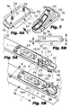
- the cross-country ski 10 has a length direction L, sides 3a, 3b with a width W therebetween and a thickness H perpendicular to the length and width. Further the ski 10 comprises a top surface 13 extending in directions of the length and the width, and of course a bottom surface 3c, which is intended to contact with the snow, which bottom surface can be of any type, and hence is not described in this text.
- the skiing shoe or boot 20 has a foot covering section, not shown in the drawings, and a sole 22 with a boot length direction S5 and an outer surface 23, in fact ground/floor etc. contacting surface 23, adapted to be positioned towards the top surface 13 of the ski.
- the boot/shoe can be of any type suitable for skiing.
- the binding 1 has rigid connection components attached to the sole 21, as well as stationary locking elements receiving the mentioned rigid connection elements, and further movable locking elements disengagebly fastening the mentioned rigid connection components, which are attached on the boot, against the stationary locking elements. Both the stationary locking elements and the movable locking elements are attached to the ski 10.
- the rigid connection components are a single cleat 30 comprising a flange 31 that is at a lock distance S I from the outer surface 23 of the sole 22, and a base 24 extending from the flange 31 thereof towards the outer surface 23 of the sole.
- the base 24 has a smaller base cross-section A2 than the flange cross-section A1 of the flange 31 in question. Accordingly, the flange is at the lock distance S1from the outer surface 23 of the sole 2.
- the single cleat 30 has planar and parallel side surfaces 4a, 4b, which are parallel with the boot length direction S5 and the length direction L of the ski, and also opposite flange sections 6c, 6d extending outside the base 24 between the side surfaces 4a, 4b, whereupon these flange sections 6c, 6d are in the boot length direction S5 and in the length direction L of the ski.
- This case is shown in Figs. 1 , 2 and 6A . This variant is also described in detail later in the text.
- the typically or possibly parallel other side surfaces - not shown in the figures - can be perpendicular to the length direction L of the ski and perpendicular to the boot length direction S5, whereupon the respective other opposite flange sections 6c and 6d, shown by dashed lines in Fig. 6A , extend in a direction perpendicular to the boot length direction S5 and to the length direction L of the ski.
- the slide 7 - described later in this text - have two parallel forks 56a, 56b extending in the length direction L of the ski for locking the cleat to the ski.
- the frame opening 14 of the frame plate 9 has naturally such dimensions, which respect to those of the flange section and the base of the cleat 30 in a way, which enable insertion of the cleat inside the single frame plate 9.
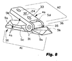
- the transition from the base 24 with smaller base cross-sectional area A2 to the flange 31 with larger flange cross-section A1 can be attained by an abrupt step as shown in figures 2 , 6A and 6B - exhibiting a clearly limited base and a flange, or by an even or gradual transformation as shown in figures 5A, 5B and 8 - exhibiting substantial chamfers or bevels 5a, 5b and 5c, 5d (bevel 5d, not visible in Fig. 8 , is opposite to the visible bevel 5c) between the opposite top and bottom surface and along the sides of the cleat 30.
- bevels are e.g. for avoiding effects of snow.
- the described rigid cleat is practical in skies for skating style.
- the base 24 of the cleat 30 has a contact surface 32 directed away from the flange 31 and adapted to seat against the outer surface 23 of the sole 21.
- the cleat 30 comprises first holes 33 for first fastening elements 34, with which fastening elements the cleat 30 is fixed to the sole 22.
- the fastening elements can be screws, for example. It is also possible that the cleat is fixed to the sole by embedding the cleat partly inside the sole. In this case, the cleat may have a form which facilitates the attachment in side the sole.
- the cleat is fixed to the sole in such a position, where - in the first and second embodiment - the side surfaces 4a, 4b and the opposite flange sections 6c, 6d extend at the boot length S5, or - in the fourth embodiment - the side surfaces and the opposite flange sections 6e, 6f extend perpendicular to the boot length S5, respectively.
- either the side surfaces and the opposite flange sections extend parallel with the ski length direction L, or alternatively the side surfaces and the opposite flange sections extend in directions perpendicular to the ski length direction L.
- the length direction L of the ski is substantially parallel with the boot length direction S5, but it shall be noted, that there can be a small or moderate angle between the ski length direction L and the boot length S5.
- the sole of the boot has protrusions or "risers” at the sides of the sole, extending from the bottom surface of the sole.
- These risers preferably have such a height that the risers carry the user against the ground when the boots are not on a ski, instead of the cleat 30.
- the risers thus preferably extend from the sole surface at least as much as the cleat.
- the risers are preferably so located on the sole that the ski is between the risers when the boot is attached to a ski.
- the risers thus follow the ski edge outside the ski.
- the risers thus make walking with the boots more comfortable, and the cleat is not damaged due to carrying the weight of the user while standing or walking without skis.
- the risers also serve to avoid snow and ice from gathering and attaching to the cleat. Still, the risers do not increase the distance between a ski and the foot of the user.
- the risers also give more torsion and hold especially in skiing downhill.
- the stationary locking elements in the binding comprises a single frame plate 9 with a frame thickness T1, which is smaller than the lock distance S1 of the cleat 30.
- This single frame plate 9 has a frame opening 14, which has an opening cross-section A3 larger than the base cross-section A2 of the cleat 30 and simultaneously larger than the flange cross-section A1 of the cleat 30, so that the cleat 30 can be inserted in direction IN into and through the frame opening 14.
- the "cross-section” means cross-sectional dimensions, which are in alignment with each respective other dimension, i.e. each respective pair of dimensions are compared for determining whether cross-section is smaller or larger.
- the mentioned inserting happens by pressing the shoe/boot 20 downwards - typically with the foot inside the shoe/boot, whereupon the cleat 30 is pushed into and through the frame opening 14 of the frame plate 9.
- the single frame plate 9 further comprises second holes 15 for second fastening elements 16, with which the frame plate 9 is fixed to the ski 10 on the top surface 13 side thereof in a position, which enable inserting the cleat 30 such that the boot length direction S5 is parallel with the length direction L of the ski 10.
- the above described single frame plate 9 can be fixed directly to the ski 10 such that the frame plate is in contact with the top surface 13 of the ski, or alternatively the above described single frame plate 9 can be fixed to the ski 10 such that there is a support plate 40 between the frame plate and the top surface 13 of the ski.
- the support plate 40 - when included in the binding 1 - has a support thickness S2 bigger than the flange thickness S3 of the flange 31, whereupon the cleat when inserted is not against the ski.
- the support plate 40 also has a support opening 41, which has a support cross-section A4 that is larger than the flange cross-section A1. Accordingly, the possible support plate 40 is attached between the frame plate 9 and the top surface 13 of the ski 10.
- the binding 1 further comprises a cavity 42 on the top surface 13 of the ski 1.
- This cavity 42 has a depth S4 bigger than a flange thickness S3 of the flange 31 and a cavity cross-section A5 larger than the flange cross-section A1, whereupon the cleat when inserted is not against the internal sections of the ski.
- the support opening 40 and the cavity 42 are for receiving the cleat deep enough, so that the outer surface 23 of the sole can be pressed against the upper surface 19 of the frame plate 9. This way the boot/shoe and the foot can be positioned as close to the ski 10 as possible.
- the support plate 40 or the frame plate 9 may have snow removal channel or channels 47, which extend from the support opening 41 of the support plate 40 or from the cavity 42 of the ski 10 to the outside of the binding 1. Closing the lever 8 or the slide 7 pushes possible superfluous snow away from around the cleat, so ensuring fixing the boot into the ski.
- the movable locking elements comprises a lever 8 or a slide 7 movable in closing and opening directions P1, P2, which can be linear movement directions- as shown in Figs. 5A and 5B , or rotary movement directions- as shown in Figs. 1 to 4 .
- Moving directions P1 and P2 are anyway substantially parallel to the top surface 13 of the ski, whereupon possible deviations of a few degrees are allowable, as caused by a sphenoid support plate or a sphenoid frame plate - as visible in Fig. 3 .
- the closing and opening directions P1, P2 are parallel with the top surface 13 of the ski or parallel with upper surface 43 of the support plate.
- the lever/slide moves between the outer surface 23 of the boot and the flange 31 on the base 24, when the boot/shoe is pressed against the ski with the cleat 30 in the frame opening 14 of the frame plate 9.
- the lever 8 or the slide 7 moves against the base 24 of the cleat between cleat's flange 31 and the frame plate 9 to attain the fixing of the boot 20 into the cross-country ski 10 - this is the closing movement direction, and respectively away from contact with the base 24 for the disengagement of the boot 20 - this is the opening movement direction.
- the lever 8 and the slide 7, whichever is present in the construction, is positioned between the frame plate 9 and the top surface 13 of the ski, or between the frame plate 9 and the support plate 40 respectively.
- the lever 8 has an operated arm 27, which is used e.g. by hand or the like, and an acting arm 28, which becomes strained against the cleat when the lever 8 is rotated around an axis 2 being between the operated arm 27 and the acting arm 28, which axis 2 is substantially perpendicular to the top surface 13 of the ski 10.
- the operated arm 27 and the acting arm 28 has a common form of the letter L , whereupon the operated arm 27 is generally longer than the acting arm 28. This configuration enables high enough closing force between the acting arm 28 and the cleat 30 to push possible snow away and ensure reliable locking of the boot.
- the slide 7 is movable linearly in the length L direction of the ski 10 as shown in Figs. 5A and 5B .
- the slide 7 has an end 53, which presses against the base 24 of the cleat 30 between the flange 31 and the sole 22 just like the acting arm 28 of the lever.
- the slide 7 can have two parallel forks 56a, 56b extending in the length direction L of the ski along those sides of the cleat 30 parallel with the length direction L and having the alternative flange sections 6e and 6f.
- the cleat comprises two flange sections 6e, 6f extending perpendicular to the length direction L of the ski 10 as mentioned earlier in this text.
- the slide 7 can be operated by a twisting knob 60, which is rotatable around an axis line 61 perpendicular to the top surface 13 of the ski 10.
- the knob also has a downward directed spindle with an axis line 62, which spindle protrudes into a transversal groove 63 of the slide 7. Twisting the knob 60 in directions P3 and P4 makes the spindle with the axis line 62 to co-operate with the transversal groove 63 so that the slide moves longitudinally in directions P1, P2, as can be easily understood by using the information from the figures, too.
- the turning movements cause closing-opening of the lever 8 and the slide 7.
- the cleat 30 is a single and stiff piece, which alternative is shown in figures 1 , 2 , 5A-5B and 6A-6B .
- the boot/shoe is kept tightly against the ski so that the heel of the boot/shoe remains substantially in contact with the ski.
- the flange 31 and the base 24 of the cleat 30 are separate pieces, but connected by a swivel 35 to each other, whereupon the base is e.g. inside the flange which surrounds the base respectively.
- the binding 1 accordingly comprises a swivel 35, which has an axis line 36 across the separate base 24 and separate flange 31 of the single cleat 30 in such a way that the axis line 36 is parallel with the width W of the ski 10, which alternative is shown in figures 7 and 8 .
- the first holes 33 for first fastening elements 34 are in the swiveling separate base 24.
- the heel of the boot/shoe is allowed to tilt upwards from the ski.
- Figure 10 illustrates a further exemplary embodiment of a binding according to the invention.
- the Figure shows the cleat 30 of a boot inside the binding.
- the cleat has projections 39 as a formation by which it is possible to achieve a more accurate positioning of the cleat in the binding.
- the cleat is locked between parts 9a and 7 of the binding; slide 7 is movable by the knob 60 in order to lock/release the cleat.
- FIGs 11a and 11b illustrate an exemplary arrangement where a same boot/cleat can be used with skating style skiing and classic style skiing.
- the cleat 30 has a swiveling base part 24 fixed to the boot.
- the base part 24 also has a projection 38 by which the base part can be locked from swiveling.
- a skating style ski has a binding where the rear locking part 9b has an opening 9r at the location of the projection 38. This way the base part 24 is able to tilt.
- the binding has a different rear locking part 9c where the location of the projection 38 is closed 9s.
- the part 9c thus locks the base part 24 and prevents it from swiveling.
- This arrangement can be used in e.g. pursuit skiing, which includes both skating style and classic style skiing.
- the motor can be arranged to rotate the knob 60 into a locking position when the cleat is inserted into the locking element of the ski binding.
- the rigid locking element may include electrical contacts which are shorted by the metal cleat when inserted into the locking element. Shorting the electrical circuit then activates the electric motor to move the movable locking parts into locking position.
- the circuit may also include a push button switch which activates the motor to unlock the movable locking parts when the user wants to release the locking.
- the electrical circuit also includes a battery and control electronics to provide these functions as understood by a person skilled in the art.
- the present invention may also be adapted for using with other types of bindings.
- the support plate may have a mechanical connection to a binding module of another binding system according to publication US 2007/0138765 A1 , for example.
- the mechanical connection can be provided by specific grooves and/or protrusions in the sides of the support plate, for example. If a user already has boots for another binding system the user can still use skis with a binding according to the present invention by attaching a binding module in accordance with the other system to the ski binding of the present invention.
Landscapes
- Health & Medical Sciences (AREA)
- General Health & Medical Sciences (AREA)
- Physical Education & Sports Medicine (AREA)
- Footwear And Its Accessory, Manufacturing Method And Apparatuses (AREA)
Claims (15)
- Bindung (1), mit der ein Stiefel (20) in einem Ski (10) entriegelbar fixiert wird:- wobei der Ski (10) eine Längsrichtung (L), Seiten (3a, 3b) mit einer dazwischenliegenden Breite (W) und einer Dicke (H) senkrecht zur besagten Länge und Breite hat, wie auch eine obere Fläche (13), die sich in Richtungen besagter Länge und Breite hat, wie auch eine obere Fläche (13), die sich in Richtungen besagter Länge und Breite erstreckt;- wobei der Stiefel (20) einen den Fuß überdeckenden Abschnitt, sowie eine Sohle (22) mit einer Stiefel-Längsrichtung (S5) und einer Außenfläche (23) hat, die zur Positionierung gegenüber besagter oberen Fläche (13) des Skis bestimmt ist, wobei die Bindung (1) hat:- starre Verbindungsbestandteile, die an besagter Sohle (21) fixierbar sind, wie auch- stationäre Arretierelemente, die besagte starre Verbindungselemente aufnehmen, und bewegbare Arretierelemente, mit denen die besagten starren Verbindungsbestandteile in dem Stiefel gegen die besagten stationären Arretierelemente entriegelbar befestigtbar sind, wobei beide diese Elemente an besagtem Ski (10) festlegbar sind,- besagte starre Verbindungsbestandteile eine Leiste (30) mit einem Flansch (31) in einem Verriegelabstand (S1) von besagter äußeren Fläche (23) der Sohle (22) sind, und eine Basis (24), die sich von besagten Flansch gegen besagte Außenfläche (23) der Sohle erstreckt, wobei die Basis einen kleineren Basis-Querschnitt (A2) als ein Flansch-Querschnitt (A1) desselben Flansches hat;dadurch gekennzeichnet, dass- besagte stationäre Arretierelemente eine einzelne Rahmenplatte (9) mit einer Rahmenöffnung (14) aufweist, die einen Öffnungsquerschnitt (A3) hat, der größer ist als besagter Basis-Querschnitt (A2) und größer als besagter Flansch-Querschnitt (A1), sodass die Leiste (30) in besagter Rahmenöffnung (14) eingesetzt werden kann; und- wobei besagte bewegbare Arretierelemente einen Hebel (8) oder einen Schlitten (7) aufweisen, der in Richtungen (P1 oder P2) parallel zu besagter oberen Fläche (13) des Skis bewegbar ist, wobei besagter Hebel/Schlitten zwischen besagter äußeren Fläche (23) des Stiefels und besagtem Flansch (31) besagter Basis (24) ist.
- Bindung gemäß Anspruch 1, dadurch gekennzeichnet, dass besagte Leiste (30) planare und parallele Seitenflächen (4a, 4b) und gegenüberliegende Flanschabschnitte (6c, 6d) hat, die sich außerhalb besagter Basis (24) zwischen den Seitenflächen (4a, 4b) erstrecken, und vorzugsweise- Seitenflächen (4a, 4b) parallel zu der Längsrichtung (L) sind, und besagte gegenüberliegende Flanschabschnitte (6c, 6d) sich in besagter Längsrichtung (L) erstrecken, ODER- besagte Seitenflächen (4a, 4b) senkrecht zur besagten Längsrichtung (L) sind, und besagte gegenüberliegende Flanschabschnitte (6c, 6d) sich in Richtungen senkrecht zur besagten Längsrichtung (L) erstrecken.
- Bindung gemäß Anspruch 1, dadurch gekennzeichnet, dass besagte Basis der Leiste eine Kontaktfläche (32) hat, die von besagtem Flansch (31) weggerichtet ist und dazu bestimmt ist, gegen besagte Außenfläche (23) der Sohle (21) zu sitzen.
- Bindung gemäß Anspruch 2, dadurch gekennzeichnet, dass besagte Leiste erste Löcher (33) für erste Befestigungselemente (34) aufweist, mit denen besagte Leiste (30) an der Sohle (22) in einer Position fixiert wird, wo sich die Seitenflächen (4a, 4b) und die gegenüberliegenden Flansch-Abschnitte (6c, 6d) an der Schuhlänge (S5) erstrecken.
- Bindung gemäß Anspruch 1, dadurch gekennzeichnet, dass die einzelne Rahmenplatte (9) eine Rahmendicke (T1) hat, die kleiner ist als besagter Arretierabstand (S1) der Leiste (30).
- Bindung gemäß Anspruch 1, dadurch gekennzeichnet, dass die einzelne Rahmenplatte (9) zweite Löcher (15) für zweite Befestigungselemente (16) aufweist, mit denen die besagte Rahmenplatte (9) an dem Ski (10) auf dessen oberer Flächen-(13)-Seite in einer Position fixiert wird, die ein Einsetzen der Leiste (30) ermöglicht, derart, dass sich deren Seitenflächen (4a, 4b) und besagte gegenüberliegende Flanschabschnitte (6c, 6d) entlang der besagten Länge (L) des Skis (10) erstrecken.
- Bindung gemäß Anspruch 1 oder 6, dadurch gekennzeichnet, dass die Bindung (1) ferner aufweist:- eine Stützplatte (40) mit einer Stützdicke (S2), die größer ist als eine Flanschdicke (S3) des besagten Flansches (31) und mit einer Stützöffnung (41), mit einem Stützquerschnitt (A4), der größer ist als besagter Flansch-Querschnitt (A1), wobei die Stützplatte (40) zwischen der besagten Rahmenplatte (9) und besagter oberen Fläche (13) des Skis (1) festgelegt ist; ODER- einen Hohlraum (42) auf der oberen Fläche (13) des Skis (1), wobei besagter Hohlraum (42) eine Tiefe (S4) hat, die größer als eine Flanschdicke (S3) des Flansches (31), und einen Hohlraum-Querschnitt (A5), der größer ist als besagter Flansch-Querschnitt (A1).
- Bindung gemäß Anspruch 1, dadurch gekennzeichnet, dass sich der Hebel (8) oder besagter Schlitten (7) gegen besagte Basis (24) der Leiste zwischen dem Leisten-Flansch (31) und der Rahmenplatte (9) bewegen, um besagtes Fixieren des Stiefels in dem Ski (1) zu erzielen, und jeweils weg von einem Kontakt mit besagter Basis (24) zum besagten Entriegeln des Stiefels.
- Bindung nach Anspruch 7, dadurch gekennzeichnet, dass- besagter Hebel (8) zwischen der Rahmenplatte (9) und der oberen Fläche (13) oder zwischen der Rahmenplatte (9) und der Stützplatte (40) jeweils bewegbar ist durch Drehung um eine Achse (2), die senkrecht auf besagte obere Fläche (13) des Skis (10) steht, oder- besagter Schlitten (7) zwischen der Rahmenplatte (9) und der oberen Fläche (13) oder zwischen der Rahmenplatte (9) und der Stützplatte (40) jeweils linear bewegbar ist in der Längs-(L)-Richtung des Skis (10).
- Bindung gemäß Anspruch 1 oder 5, dadurch gekennzeichnet, dass der Schlitten (7) hat:- ein Ende (53) in einer längsseitigen ersten Öffnung (55), deren Ende sich gegen besagte Basis der Leiste (30) zwischen besagtem Flansch (31) und der Sohle (22) drückt; oder- zwei parallele Gabeln (56a, 56b), die sich in der Längsrichtung (L) des Skis über solche Seiten der Leiste (30) erstrecken, die parallel zur Längsrichtung (L) sind und weg von diesen, wobei die Leiste zwei Flanschabschnitte (6e, 6f) aufweist, die sich senkrecht zur Längsrichtung (L) erstrecken.
- Bindung nach Anspruch 1, dadurch gekennzeichnet, dass zum Kürlauf-Skifahren besagte Leiste (30) ein einzelnes und starres Teil ist.
- Bindung gemäß Anspruch 1, dadurch gekennzeichnet, dass für einen klassischen Skifahrstyle:- der Flansch (31) und die Basis (24) der Leiste (30) separate Teile sind, während die Basis innerhalb des Flansches ist, der die Basis jeweils umschließt;- die Bindung (1) ferner ein Drehlager (35) aufweist, das eine Achslinie (36) über eine separate Basis (24) und einen separaten Flansch (31) hat, um mit besagter Breite (W) des Skis (10) ausgerichtet zu sein, sowie erste Löcher (33) für erste Befestigungselemente (34) in der separaten Basis (24).
- Ski mit einer Bindungsstruktur für einen Stiefel, dadurch gekennzeichnet, dass die Bindungsstruktur gemäß einem der Ansprüche 1 - 12 ausgeführt ist.
- Skistiefel mit einer Bindungsstruktur für einen Ski, dadurch gekennzeichnet, dass die Bindungsstruktur gemäß einem der Ansprüche 1 - 12 ausgeführt ist.
- Skistiefel gemäß Anspruch 14, dadurch gekennzeichnet, dass die Stiefelsohle Stege (91-94) nahe zu den Seiten der Stiefelsohle aufweist, welche Stege sich von der unteren Fläche der Schuhsohle erstrecken, um ein Gewicht des Anwenders zu tragen, wenn dieser ohne Ski auf dem Boden steht, wobei der laterale Abstand zwischen den Stegen vorzugsweise gleich oder größer ist als die Breite eines Skis im Bereich der Bindung, wobei der Ski zwischen den Stegen ist, wenn der Ski und der Stiefel mit der Bindung festgelegt sind.
Priority Applications (4)
| Application Number | Priority Date | Filing Date | Title |
|---|---|---|---|
| CA2816199A CA2816199A1 (en) | 2012-07-02 | 2013-05-23 | Ski, boot and binding between a ski and a boot |
| RU2013128997A RU2630438C2 (ru) | 2012-07-02 | 2013-06-26 | Крепление для разъемной фиксации ботинка на лыже, лыжа с устройством крепления для ботинка и лыжный ботинок с устройством крепления к лыже |
| US13/932,266 US8752858B2 (en) | 2012-07-02 | 2013-07-01 | Ski, boot and binding between a ski and a boot |
| JP2013137801A JP2014012137A (ja) | 2012-07-02 | 2013-07-01 | スキー、ブーツ、及びスキーとブーツ間のビンディング |
Applications Claiming Priority (1)
| Application Number | Priority Date | Filing Date | Title |
|---|---|---|---|
| FI20125765A FI124134B (en) | 2012-07-02 | 2012-07-02 | Binding between a ski and a ski boot |
Publications (2)
| Publication Number | Publication Date |
|---|---|
| EP2682165A1 EP2682165A1 (de) | 2014-01-08 |
| EP2682165B1 true EP2682165B1 (de) | 2014-10-29 |
Family
ID=47826947
Family Applications (1)
| Application Number | Title | Priority Date | Filing Date |
|---|---|---|---|
| EP13157272.9A Active EP2682165B1 (de) | 2012-07-02 | 2013-02-28 | Bindung zwischen einem Ski und einem Schuh |
Country Status (6)
| Country | Link |
|---|---|
| US (1) | US8752858B2 (de) |
| EP (1) | EP2682165B1 (de) |
| JP (1) | JP2014012137A (de) |
| CA (1) | CA2816199A1 (de) |
| FI (1) | FI124134B (de) |
| RU (1) | RU2630438C2 (de) |
Cited By (2)
| Publication number | Priority date | Publication date | Assignee | Title |
|---|---|---|---|---|
| RU2851008C2 (ru) * | 2021-05-03 | 2025-11-17 | Роттефелла Ас | Устройство скоб для лыжных ботинок |
| EP4678250A1 (de) * | 2024-07-10 | 2026-01-14 | Skis Rossignol | Skibindung für den langlauf und langlaufski mit einer solchen bindung |
Families Citing this family (7)
| Publication number | Priority date | Publication date | Assignee | Title |
|---|---|---|---|---|
| FI124134B (en) * | 2012-07-02 | 2014-03-31 | One Way Sport Oy | Binding between a ski and a ski boot |
| EA034820B1 (ru) | 2015-02-17 | 2020-03-25 | Эли Лилли Энд Компани | Порошковый состав для интраназального введения для лечения гипогликемии |
| AT519523A1 (de) * | 2016-12-19 | 2018-07-15 | Fischer Sports Gmbh | Langlaufbindung |
| NO342264B1 (no) * | 2017-02-03 | 2018-04-30 | Rottefella As | Monteringssystem for binding |
| DE102017120701A1 (de) | 2017-09-07 | 2019-03-07 | Marker Deutschland Gmbh | Ultraleichter Vorderbacken |
| TWI771669B (zh) | 2019-04-26 | 2022-07-21 | 美商美國禮來大藥廠 | 製備穩定胜肽調配物之方法 |
| NO349029B1 (no) * | 2021-05-03 | 2025-09-01 | Rottefella As | Cleats-arrangement for skisko |
Family Cites Families (14)
| Publication number | Priority date | Publication date | Assignee | Title |
|---|---|---|---|---|
| US4613150A (en) * | 1981-08-17 | 1986-09-23 | Warrington Inc. | Toe binding for skis |
| EP0084813B1 (de) * | 1982-01-27 | 1987-03-25 | Haldemann A.G. | Sicherheitsskibindung |
| SU1377129A1 (ru) * | 1985-04-26 | 1988-02-28 | Ленинградский Политехнический Институт Им.М.И.Калинина | Лыжна принадлежность |
| US5505477A (en) * | 1993-07-19 | 1996-04-09 | K-2 Corporation | Snowboard binding |
| DE4343485C1 (de) * | 1993-09-14 | 1995-03-30 | Rottefella As | Anordnung einer Langlaufskibindung |
| FR2711488B1 (fr) | 1993-10-25 | 1995-11-24 | Rossignol Sa | Chaussure de ski de fond et ensemble ski-fixation-chaussure pour la pratique du ski de fond. |
| US6877399B1 (en) * | 1997-09-03 | 2005-04-12 | Bicycle pedal that can fit a multiplicity of shoe cleats | |
| FR2772627B1 (fr) * | 1997-12-23 | 2000-03-10 | Salomon Sa | Systeme de liaison rapide d'une chaussure a un article de sport |
| EP1669113A1 (de) * | 2004-12-07 | 2006-06-14 | Mikael Östberg | Skibindung |
| FR2894836B1 (fr) | 2005-12-16 | 2008-02-22 | Salomon Sa | Ensemble ski de fond et dispositif de fixation de ski de fond |
| US20080047168A1 (en) * | 2006-06-23 | 2008-02-28 | Svensson John E | Nordic ski boot support and attachment structure |
| DE102007018648A1 (de) * | 2006-11-28 | 2008-01-17 | Rottefella As | Vorrichtung zum Anschluß eines Schuhs an ein Schneegleitgerät |
| RU73610U1 (ru) * | 2007-12-19 | 2008-05-27 | Виктор Анатольевич Бушменев | Лыжное крепление |
| FI124134B (en) * | 2012-07-02 | 2014-03-31 | One Way Sport Oy | Binding between a ski and a ski boot |
-
2012
- 2012-07-02 FI FI20125765A patent/FI124134B/en not_active IP Right Cessation
-
2013
- 2013-02-28 EP EP13157272.9A patent/EP2682165B1/de active Active
- 2013-05-23 CA CA2816199A patent/CA2816199A1/en not_active Abandoned
- 2013-06-26 RU RU2013128997A patent/RU2630438C2/ru not_active IP Right Cessation
- 2013-07-01 JP JP2013137801A patent/JP2014012137A/ja active Pending
- 2013-07-01 US US13/932,266 patent/US8752858B2/en active Active
Cited By (3)
| Publication number | Priority date | Publication date | Assignee | Title |
|---|---|---|---|---|
| RU2851008C2 (ru) * | 2021-05-03 | 2025-11-17 | Роттефелла Ас | Устройство скоб для лыжных ботинок |
| EP4678250A1 (de) * | 2024-07-10 | 2026-01-14 | Skis Rossignol | Skibindung für den langlauf und langlaufski mit einer solchen bindung |
| FR3164398A1 (fr) * | 2024-07-10 | 2026-01-16 | Skis Rossignol | Fixation pour le ski de fond |
Also Published As
| Publication number | Publication date |
|---|---|
| FI124134B (en) | 2014-03-31 |
| RU2630438C2 (ru) | 2017-09-07 |
| US8752858B2 (en) | 2014-06-17 |
| US20140001733A1 (en) | 2014-01-02 |
| FI20125765L (fi) | 2014-01-03 |
| EP2682165A1 (de) | 2014-01-08 |
| RU2013128997A (ru) | 2015-01-10 |
| CA2816199A1 (en) | 2014-01-02 |
| JP2014012137A (ja) | 2014-01-23 |
Similar Documents
| Publication | Publication Date | Title |
|---|---|---|
| EP2682165B1 (de) | Bindung zwischen einem Ski und einem Schuh | |
| CN103108679B (zh) | 旅行或越野雪橇固定装置 | |
| US9227131B2 (en) | Four-part gliding apparatus | |
| EP0857499B1 (de) | Skischuhbindungssystem für Snowboards | |
| US8973924B2 (en) | Device for adjusting the position of the boot support holder in a ski fastening system | |
| EP2772287B1 (de) | Beuger | |
| WO2012045374A1 (en) | Ski binding | |
| US20100257754A1 (en) | Ski-boot with means for actuating corresponding engaging members of ski-touring bindings | |
| US20150250257A1 (en) | Ski boot | |
| US12318679B2 (en) | Device for retaining a boot on a gliding board and gliding apparatus comprising such a device | |
| US20040056449A1 (en) | Binding device with front unfastening | |
| RU2525476C2 (ru) | Лыжное крепление | |
| CN104225903B (zh) | 安全滑雪橇绑定系统 | |
| EP4417080A1 (de) | Skischuh | |
| US9050521B2 (en) | Cross-country ski system provided with a direct bearing lateral surface |
Legal Events
| Date | Code | Title | Description |
|---|---|---|---|
| PUAI | Public reference made under article 153(3) epc to a published international application that has entered the european phase |
Free format text: ORIGINAL CODE: 0009012 |
|
| AK | Designated contracting states |
Kind code of ref document: A1 Designated state(s): AL AT BE BG CH CY CZ DE DK EE ES FI FR GB GR HR HU IE IS IT LI LT LU LV MC MK MT NL NO PL PT RO RS SE SI SK SM TR |
|
| AX | Request for extension of the european patent |
Extension state: BA ME |
|
| 17P | Request for examination filed |
Effective date: 20140124 |
|
| RBV | Designated contracting states (corrected) |
Designated state(s): AL AT BE BG CH CY CZ DE DK EE ES FI FR GB GR HR HU IE IS IT LI LT LU LV MC MK MT NL NO PL PT RO RS SE SI SK SM TR |
|
| GRAP | Despatch of communication of intention to grant a patent |
Free format text: ORIGINAL CODE: EPIDOSNIGR1 |
|
| RIC1 | Information provided on ipc code assigned before grant |
Ipc: A63C 9/086 20120101AFI20140217BHEP Ipc: A63C 9/00 20120101ALI20140217BHEP Ipc: A63C 9/08 20120101ALI20140217BHEP |
|
| RIC1 | Information provided on ipc code assigned before grant |
Ipc: A63C 9/086 20120101ALI20140224BHEP Ipc: A63C 9/08 20120101ALI20140224BHEP Ipc: A63C 9/00 20120101ALI20140224BHEP Ipc: A43B 5/04 20060101AFI20140224BHEP |
|
| INTG | Intention to grant announced |
Effective date: 20140321 |
|
| GRAS | Grant fee paid |
Free format text: ORIGINAL CODE: EPIDOSNIGR3 |
|
| REG | Reference to a national code |
Ref country code: DE Ref legal event code: R079 Ref document number: 602013000392 Country of ref document: DE Free format text: PREVIOUS MAIN CLASS: A63C0009086000 Ipc: A63C0009200000 |
|
| GRAP | Despatch of communication of intention to grant a patent |
Free format text: ORIGINAL CODE: EPIDOSNIGR1 |
|
| RIC1 | Information provided on ipc code assigned before grant |
Ipc: A43B 5/04 20060101ALI20140822BHEP Ipc: A63C 9/00 20120101ALI20140822BHEP Ipc: A63C 9/20 20120101AFI20140822BHEP Ipc: A63C 9/086 20120101ALI20140822BHEP |
|
| GRAA | (expected) grant |
Free format text: ORIGINAL CODE: 0009210 |
|
| INTG | Intention to grant announced |
Effective date: 20140917 |
|
| AK | Designated contracting states |
Kind code of ref document: B1 Designated state(s): AL AT BE BG CH CY CZ DE DK EE ES FI FR GB GR HR HU IE IS IT LI LT LU LV MC MK MT NL NO PL PT RO RS SE SI SK SM TR |
|
| REG | Reference to a national code |
Ref country code: GB Ref legal event code: FG4D |
|
| REG | Reference to a national code |
Ref country code: CH Ref legal event code: EP |
|
| REG | Reference to a national code |
Ref country code: AT Ref legal event code: REF Ref document number: 693266 Country of ref document: AT Kind code of ref document: T Effective date: 20141115 |
|
| REG | Reference to a national code |
Ref country code: IE Ref legal event code: FG4D |
|
| REG | Reference to a national code |
Ref country code: DE Ref legal event code: R096 Ref document number: 602013000392 Country of ref document: DE Effective date: 20141211 |
|
| REG | Reference to a national code |
Ref country code: SE Ref legal event code: TRGR |
|
| REG | Reference to a national code |
Ref country code: CH Ref legal event code: NV Representative=s name: PATENTANWAELTE SCHAAD, BALASS, MENZL AND PARTN, CH |
|
| REG | Reference to a national code |
Ref country code: NL Ref legal event code: VDEP Effective date: 20141029 |
|
| REG | Reference to a national code |
Ref country code: LT Ref legal event code: MG4D |
|
| REG | Reference to a national code |
Ref country code: NO Ref legal event code: T2 Effective date: 20141029 |
|
| PG25 | Lapsed in a contracting state [announced via postgrant information from national office to epo] |
Ref country code: IS Free format text: LAPSE BECAUSE OF FAILURE TO SUBMIT A TRANSLATION OF THE DESCRIPTION OR TO PAY THE FEE WITHIN THE PRESCRIBED TIME-LIMIT Effective date: 20150228 Ref country code: NL Free format text: LAPSE BECAUSE OF FAILURE TO SUBMIT A TRANSLATION OF THE DESCRIPTION OR TO PAY THE FEE WITHIN THE PRESCRIBED TIME-LIMIT Effective date: 20141029 Ref country code: PT Free format text: LAPSE BECAUSE OF FAILURE TO SUBMIT A TRANSLATION OF THE DESCRIPTION OR TO PAY THE FEE WITHIN THE PRESCRIBED TIME-LIMIT Effective date: 20150302 Ref country code: ES Free format text: LAPSE BECAUSE OF FAILURE TO SUBMIT A TRANSLATION OF THE DESCRIPTION OR TO PAY THE FEE WITHIN THE PRESCRIBED TIME-LIMIT Effective date: 20141029 Ref country code: LT Free format text: LAPSE BECAUSE OF FAILURE TO SUBMIT A TRANSLATION OF THE DESCRIPTION OR TO PAY THE FEE WITHIN THE PRESCRIBED TIME-LIMIT Effective date: 20141029 |
|
| PG25 | Lapsed in a contracting state [announced via postgrant information from national office to epo] |
Ref country code: CY Free format text: LAPSE BECAUSE OF FAILURE TO SUBMIT A TRANSLATION OF THE DESCRIPTION OR TO PAY THE FEE WITHIN THE PRESCRIBED TIME-LIMIT Effective date: 20141029 Ref country code: HR Free format text: LAPSE BECAUSE OF FAILURE TO SUBMIT A TRANSLATION OF THE DESCRIPTION OR TO PAY THE FEE WITHIN THE PRESCRIBED TIME-LIMIT Effective date: 20141029 Ref country code: PL Free format text: LAPSE BECAUSE OF FAILURE TO SUBMIT A TRANSLATION OF THE DESCRIPTION OR TO PAY THE FEE WITHIN THE PRESCRIBED TIME-LIMIT Effective date: 20141029 Ref country code: RS Free format text: LAPSE BECAUSE OF FAILURE TO SUBMIT A TRANSLATION OF THE DESCRIPTION OR TO PAY THE FEE WITHIN THE PRESCRIBED TIME-LIMIT Effective date: 20141029 Ref country code: LV Free format text: LAPSE BECAUSE OF FAILURE TO SUBMIT A TRANSLATION OF THE DESCRIPTION OR TO PAY THE FEE WITHIN THE PRESCRIBED TIME-LIMIT Effective date: 20141029 Ref country code: GR Free format text: LAPSE BECAUSE OF FAILURE TO SUBMIT A TRANSLATION OF THE DESCRIPTION OR TO PAY THE FEE WITHIN THE PRESCRIBED TIME-LIMIT Effective date: 20150130 |
|
| REG | Reference to a national code |
Ref country code: DE Ref legal event code: R097 Ref document number: 602013000392 Country of ref document: DE |
|
| PG25 | Lapsed in a contracting state [announced via postgrant information from national office to epo] |
Ref country code: SK Free format text: LAPSE BECAUSE OF FAILURE TO SUBMIT A TRANSLATION OF THE DESCRIPTION OR TO PAY THE FEE WITHIN THE PRESCRIBED TIME-LIMIT Effective date: 20141029 Ref country code: CZ Free format text: LAPSE BECAUSE OF FAILURE TO SUBMIT A TRANSLATION OF THE DESCRIPTION OR TO PAY THE FEE WITHIN THE PRESCRIBED TIME-LIMIT Effective date: 20141029 Ref country code: EE Free format text: LAPSE BECAUSE OF FAILURE TO SUBMIT A TRANSLATION OF THE DESCRIPTION OR TO PAY THE FEE WITHIN THE PRESCRIBED TIME-LIMIT Effective date: 20141029 Ref country code: RO Free format text: LAPSE BECAUSE OF FAILURE TO SUBMIT A TRANSLATION OF THE DESCRIPTION OR TO PAY THE FEE WITHIN THE PRESCRIBED TIME-LIMIT Effective date: 20141029 Ref country code: DK Free format text: LAPSE BECAUSE OF FAILURE TO SUBMIT A TRANSLATION OF THE DESCRIPTION OR TO PAY THE FEE WITHIN THE PRESCRIBED TIME-LIMIT Effective date: 20141029 |
|
| PG25 | Lapsed in a contracting state [announced via postgrant information from national office to epo] |
Ref country code: IT Free format text: LAPSE BECAUSE OF FAILURE TO SUBMIT A TRANSLATION OF THE DESCRIPTION OR TO PAY THE FEE WITHIN THE PRESCRIBED TIME-LIMIT Effective date: 20141029 |
|
| PLBE | No opposition filed within time limit |
Free format text: ORIGINAL CODE: 0009261 |
|
| STAA | Information on the status of an ep patent application or granted ep patent |
Free format text: STATUS: NO OPPOSITION FILED WITHIN TIME LIMIT |
|
| PG25 | Lapsed in a contracting state [announced via postgrant information from national office to epo] |
Ref country code: LU Free format text: LAPSE BECAUSE OF FAILURE TO SUBMIT A TRANSLATION OF THE DESCRIPTION OR TO PAY THE FEE WITHIN THE PRESCRIBED TIME-LIMIT Effective date: 20150228 |
|
| 26N | No opposition filed |
Effective date: 20150730 |
|
| PG25 | Lapsed in a contracting state [announced via postgrant information from national office to epo] |
Ref country code: MC Free format text: LAPSE BECAUSE OF FAILURE TO SUBMIT A TRANSLATION OF THE DESCRIPTION OR TO PAY THE FEE WITHIN THE PRESCRIBED TIME-LIMIT Effective date: 20141029 |
|
| REG | Reference to a national code |
Ref country code: IE Ref legal event code: MM4A |
|
| REG | Reference to a national code |
Ref country code: FR Ref legal event code: PLFP Year of fee payment: 4 |
|
| PG25 | Lapsed in a contracting state [announced via postgrant information from national office to epo] |
Ref country code: IE Free format text: LAPSE BECAUSE OF NON-PAYMENT OF DUE FEES Effective date: 20150228 |
|
| PG25 | Lapsed in a contracting state [announced via postgrant information from national office to epo] |
Ref country code: SI Free format text: LAPSE BECAUSE OF FAILURE TO SUBMIT A TRANSLATION OF THE DESCRIPTION OR TO PAY THE FEE WITHIN THE PRESCRIBED TIME-LIMIT Effective date: 20141029 |
|
| PG25 | Lapsed in a contracting state [announced via postgrant information from national office to epo] |
Ref country code: MT Free format text: LAPSE BECAUSE OF FAILURE TO SUBMIT A TRANSLATION OF THE DESCRIPTION OR TO PAY THE FEE WITHIN THE PRESCRIBED TIME-LIMIT Effective date: 20141029 |
|
| REG | Reference to a national code |
Ref country code: FR Ref legal event code: PLFP Year of fee payment: 5 |
|
| PG25 | Lapsed in a contracting state [announced via postgrant information from national office to epo] |
Ref country code: BG Free format text: LAPSE BECAUSE OF FAILURE TO SUBMIT A TRANSLATION OF THE DESCRIPTION OR TO PAY THE FEE WITHIN THE PRESCRIBED TIME-LIMIT Effective date: 20141029 Ref country code: HU Free format text: LAPSE BECAUSE OF FAILURE TO SUBMIT A TRANSLATION OF THE DESCRIPTION OR TO PAY THE FEE WITHIN THE PRESCRIBED TIME-LIMIT; INVALID AB INITIO Effective date: 20130228 |
|
| PG25 | Lapsed in a contracting state [announced via postgrant information from national office to epo] |
Ref country code: TR Free format text: LAPSE BECAUSE OF FAILURE TO SUBMIT A TRANSLATION OF THE DESCRIPTION OR TO PAY THE FEE WITHIN THE PRESCRIBED TIME-LIMIT Effective date: 20141029 |
|
| PG25 | Lapsed in a contracting state [announced via postgrant information from national office to epo] |
Ref country code: BE Free format text: LAPSE BECAUSE OF FAILURE TO SUBMIT A TRANSLATION OF THE DESCRIPTION OR TO PAY THE FEE WITHIN THE PRESCRIBED TIME-LIMIT Effective date: 20141029 |
|
| GBPC | Gb: european patent ceased through non-payment of renewal fee |
Effective date: 20170228 |
|
| REG | Reference to a national code |
Ref country code: FR Ref legal event code: PLFP Year of fee payment: 6 |
|
| PG25 | Lapsed in a contracting state [announced via postgrant information from national office to epo] |
Ref country code: GB Free format text: LAPSE BECAUSE OF NON-PAYMENT OF DUE FEES Effective date: 20170228 |
|
| PG25 | Lapsed in a contracting state [announced via postgrant information from national office to epo] |
Ref country code: SM Free format text: LAPSE BECAUSE OF FAILURE TO SUBMIT A TRANSLATION OF THE DESCRIPTION OR TO PAY THE FEE WITHIN THE PRESCRIBED TIME-LIMIT Effective date: 20141029 |
|
| PG25 | Lapsed in a contracting state [announced via postgrant information from national office to epo] |
Ref country code: MK Free format text: LAPSE BECAUSE OF FAILURE TO SUBMIT A TRANSLATION OF THE DESCRIPTION OR TO PAY THE FEE WITHIN THE PRESCRIBED TIME-LIMIT Effective date: 20141029 |
|
| PG25 | Lapsed in a contracting state [announced via postgrant information from national office to epo] |
Ref country code: AL Free format text: LAPSE BECAUSE OF FAILURE TO SUBMIT A TRANSLATION OF THE DESCRIPTION OR TO PAY THE FEE WITHIN THE PRESCRIBED TIME-LIMIT Effective date: 20141029 |
|
| REG | Reference to a national code |
Ref country code: CH Ref legal event code: PUE Owner name: FISCHER SPORTS GMBH, AT Free format text: FORMER OWNER: ONE WAY SPORT OY, FI |
|
| REG | Reference to a national code |
Ref country code: NO Ref legal event code: CHAD Owner name: FISCHER SPORTS GMBH, AT Ref country code: NO Ref legal event code: CREP Representative=s name: BRYN AARFLOT AS, STORTINGSGATA 8, 0161 OSLO, NORGE |
|
| REG | Reference to a national code |
Ref country code: DE Ref legal event code: R082 Ref document number: 602013000392 Country of ref document: DE Representative=s name: BOEHMERT & BOEHMERT ANWALTSPARTNERSCHAFT MBB -, DE Ref country code: DE Ref legal event code: R081 Ref document number: 602013000392 Country of ref document: DE Owner name: FISCHER SPORTS GMBH, AT Free format text: FORMER OWNER: ONE WAY SPORT OY, HELSINKI, FI |
|
| REG | Reference to a national code |
Ref country code: AT Ref legal event code: PC Ref document number: 693266 Country of ref document: AT Kind code of ref document: T Owner name: FISCHER SPORTS GMBH, AT Effective date: 20191121 |
|
| PGFP | Annual fee paid to national office [announced via postgrant information from national office to epo] |
Ref country code: FI Payment date: 20230222 Year of fee payment: 11 Ref country code: CH Payment date: 20230307 Year of fee payment: 11 |
|
| PGFP | Annual fee paid to national office [announced via postgrant information from national office to epo] |
Ref country code: SE Payment date: 20230220 Year of fee payment: 11 |
|
| P01 | Opt-out of the competence of the unified patent court (upc) registered |
Effective date: 20230519 |
|
| PGFP | Annual fee paid to national office [announced via postgrant information from national office to epo] |
Ref country code: AT Payment date: 20240209 Year of fee payment: 12 |
|
| REG | Reference to a national code |
Ref country code: CH Ref legal event code: PL |
|
| PG25 | Lapsed in a contracting state [announced via postgrant information from national office to epo] |
Ref country code: FI Free format text: LAPSE BECAUSE OF NON-PAYMENT OF DUE FEES Effective date: 20240228 |
|
| REG | Reference to a national code |
Ref country code: AT Ref legal event code: MM01 Ref document number: 693266 Country of ref document: AT Kind code of ref document: T Effective date: 20240228 |
|
| PG25 | Lapsed in a contracting state [announced via postgrant information from national office to epo] |
Ref country code: CH Free format text: LAPSE BECAUSE OF NON-PAYMENT OF DUE FEES Effective date: 20240229 |
|
| PG25 | Lapsed in a contracting state [announced via postgrant information from national office to epo] |
Ref country code: AT Free format text: LAPSE BECAUSE OF NON-PAYMENT OF DUE FEES Effective date: 20240228 |
|
| REG | Reference to a national code |
Ref country code: SE Ref legal event code: EUG |
|
| PG25 | Lapsed in a contracting state [announced via postgrant information from national office to epo] |
Ref country code: FI Free format text: LAPSE BECAUSE OF NON-PAYMENT OF DUE FEES Effective date: 20240228 Ref country code: CH Free format text: LAPSE BECAUSE OF NON-PAYMENT OF DUE FEES Effective date: 20240229 Ref country code: AT Free format text: LAPSE BECAUSE OF NON-PAYMENT OF DUE FEES Effective date: 20240228 |
|
| PG25 | Lapsed in a contracting state [announced via postgrant information from national office to epo] |
Ref country code: SE Free format text: LAPSE BECAUSE OF NON-PAYMENT OF DUE FEES Effective date: 20240229 |
|
| PGFP | Annual fee paid to national office [announced via postgrant information from national office to epo] |
Ref country code: NO Payment date: 20260217 Year of fee payment: 14 Ref country code: DE Payment date: 20260217 Year of fee payment: 14 |
|
| PGFP | Annual fee paid to national office [announced via postgrant information from national office to epo] |
Ref country code: FR Payment date: 20260223 Year of fee payment: 14 |