EP2682270B1 - Druckmaterialzufuhrsystem und Kartusche - Google Patents
Druckmaterialzufuhrsystem und Kartusche Download PDFInfo
- Publication number
- EP2682270B1 EP2682270B1 EP13175085.3A EP13175085A EP2682270B1 EP 2682270 B1 EP2682270 B1 EP 2682270B1 EP 13175085 A EP13175085 A EP 13175085A EP 2682270 B1 EP2682270 B1 EP 2682270B1
- Authority
- EP
- European Patent Office
- Prior art keywords
- cartridge
- section
- axial direction
- printing material
- supply port
- Prior art date
- Legal status (The legal status is an assumption and is not a legal conclusion. Google has not performed a legal analysis and makes no representation as to the accuracy of the status listed.)
- Active
Links
- 238000007639 printing Methods 0.000 title claims description 193
- 239000000463 material Substances 0.000 title claims description 151
- 238000005192 partition Methods 0.000 claims description 34
- 230000003287 optical effect Effects 0.000 claims description 31
- 239000000976 ink Substances 0.000 description 276
- 238000010586 diagram Methods 0.000 description 89
- 239000007788 liquid Substances 0.000 description 41
- 230000006870 function Effects 0.000 description 15
- 238000003825 pressing Methods 0.000 description 15
- 239000011347 resin Substances 0.000 description 15
- 229920005989 resin Polymers 0.000 description 15
- 238000003860 storage Methods 0.000 description 13
- 230000015572 biosynthetic process Effects 0.000 description 11
- 238000005755 formation reaction Methods 0.000 description 11
- 230000000630 rising effect Effects 0.000 description 11
- 239000004743 Polypropylene Substances 0.000 description 8
- 238000001514 detection method Methods 0.000 description 8
- 229920001155 polypropylene Polymers 0.000 description 8
- 239000006260 foam Substances 0.000 description 7
- 230000009471 action Effects 0.000 description 6
- 230000007246 mechanism Effects 0.000 description 6
- 230000008859 change Effects 0.000 description 5
- 210000000078 claw Anatomy 0.000 description 4
- 238000004519 manufacturing process Methods 0.000 description 4
- 229920006324 polyoxymethylene Polymers 0.000 description 4
- -1 polypropylene Polymers 0.000 description 4
- 230000009467 reduction Effects 0.000 description 4
- 239000003086 colorant Substances 0.000 description 3
- 239000000470 constituent Substances 0.000 description 3
- 230000007547 defect Effects 0.000 description 3
- 230000000694 effects Effects 0.000 description 3
- 238000007789 sealing Methods 0.000 description 3
- 229930182556 Polyacetal Natural products 0.000 description 2
- 239000000853 adhesive Substances 0.000 description 2
- 239000002585 base Substances 0.000 description 2
- 230000000903 blocking effect Effects 0.000 description 2
- 230000037430 deletion Effects 0.000 description 2
- 238000012217 deletion Methods 0.000 description 2
- 238000005530 etching Methods 0.000 description 2
- 239000010408 film Substances 0.000 description 2
- 230000005484 gravity Effects 0.000 description 2
- 230000001788 irregular Effects 0.000 description 2
- 239000004973 liquid crystal related substance Substances 0.000 description 2
- 239000010687 lubricating oil Substances 0.000 description 2
- 238000000034 method Methods 0.000 description 2
- 230000004048 modification Effects 0.000 description 2
- 238000012986 modification Methods 0.000 description 2
- 239000002245 particle Substances 0.000 description 2
- 230000035807 sensation Effects 0.000 description 2
- 229910001220 stainless steel Inorganic materials 0.000 description 2
- 239000010935 stainless steel Substances 0.000 description 2
- 239000000126 substance Substances 0.000 description 2
- XLYOFNOQVPJJNP-UHFFFAOYSA-N water Substances O XLYOFNOQVPJJNP-UHFFFAOYSA-N 0.000 description 2
- 238000000018 DNA microarray Methods 0.000 description 1
- 239000002253 acid Substances 0.000 description 1
- 229920000122 acrylonitrile butadiene styrene Polymers 0.000 description 1
- 230000001070 adhesive effect Effects 0.000 description 1
- 239000003513 alkali Substances 0.000 description 1
- 238000004891 communication Methods 0.000 description 1
- 230000003247 decreasing effect Effects 0.000 description 1
- 230000000994 depressogenic effect Effects 0.000 description 1
- 239000000428 dust Substances 0.000 description 1
- 239000007772 electrode material Substances 0.000 description 1
- 230000004927 fusion Effects 0.000 description 1
- 239000012943 hotmelt Substances 0.000 description 1
- 229910001867 inorganic solvent Inorganic materials 0.000 description 1
- 239000003049 inorganic solvent Substances 0.000 description 1
- 239000011344 liquid material Substances 0.000 description 1
- 239000007791 liquid phase Substances 0.000 description 1
- 229910001338 liquidmetal Inorganic materials 0.000 description 1
- 239000002184 metal Substances 0.000 description 1
- 229910052751 metal Inorganic materials 0.000 description 1
- 239000002923 metal particle Substances 0.000 description 1
- 239000000203 mixture Substances 0.000 description 1
- 239000004745 nonwoven fabric Substances 0.000 description 1
- 239000003921 oil Substances 0.000 description 1
- 239000003960 organic solvent Substances 0.000 description 1
- 239000000049 pigment Substances 0.000 description 1
- 229920001955 polyphenylene ether Polymers 0.000 description 1
- 238000007790 scraping Methods 0.000 description 1
- 239000011343 solid material Substances 0.000 description 1
- 239000000243 solution Substances 0.000 description 1
- 239000002904 solvent Substances 0.000 description 1
- 239000010409 thin film Substances 0.000 description 1
Images



















Classifications
-
- B—PERFORMING OPERATIONS; TRANSPORTING
- B41—PRINTING; LINING MACHINES; TYPEWRITERS; STAMPS
- B41J—TYPEWRITERS; SELECTIVE PRINTING MECHANISMS, i.e. MECHANISMS PRINTING OTHERWISE THAN FROM A FORME; CORRECTION OF TYPOGRAPHICAL ERRORS
- B41J2/00—Typewriters or selective printing mechanisms characterised by the printing or marking process for which they are designed
- B41J2/005—Typewriters or selective printing mechanisms characterised by the printing or marking process for which they are designed characterised by bringing liquid or particles selectively into contact with a printing material
- B41J2/01—Ink jet
- B41J2/17—Ink jet characterised by ink handling
- B41J2/175—Ink supply systems ; Circuit parts therefor
- B41J2/17503—Ink cartridges
- B41J2/17553—Outer structure
-
- B—PERFORMING OPERATIONS; TRANSPORTING
- B41—PRINTING; LINING MACHINES; TYPEWRITERS; STAMPS
- B41J—TYPEWRITERS; SELECTIVE PRINTING MECHANISMS, i.e. MECHANISMS PRINTING OTHERWISE THAN FROM A FORME; CORRECTION OF TYPOGRAPHICAL ERRORS
- B41J2/00—Typewriters or selective printing mechanisms characterised by the printing or marking process for which they are designed
- B41J2/005—Typewriters or selective printing mechanisms characterised by the printing or marking process for which they are designed characterised by bringing liquid or particles selectively into contact with a printing material
- B41J2/01—Ink jet
- B41J2/17—Ink jet characterised by ink handling
- B41J2/175—Ink supply systems ; Circuit parts therefor
- B41J2/17503—Ink cartridges
- B41J2/17526—Electrical contacts to the cartridge
- B41J2/1753—Details of contacts on the cartridge, e.g. protection of contacts
Definitions
- the invention has been carried out in order to solve at least a portion of the problems described above and is able to be realized in the following aspects.
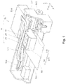
- the control section 510 of the printer 50 controls each section of the printer 50.
- the carriage 520 of the printer 50 is configured to relatively move the head 540 to the printing medium 90.
- the head 540 of the printer 50 receives supply of the ink from the cartridge 20 which is mounted on the holder 60 and discharges the ink to the printing medium 90.
- the control section 510 and the carriage 520 are electrically connected via a flexible cable 517 and the head 540 executes discharge of the ink based on a control signal from the control section 510.
- the opening edges 288 of the ink support ports 280 are sealed by a sealing member (not shown) such as a cap or a film during shipping of the cartridge 20 from the factory. After this, the sealing member (not shown) which seals the opening edge 288 is removed from the cartridge 20 during mounting of the cartridge 20 on the holder 60.
- a sealing member such as a cap or a film during shipping of the cartridge 20 from the factory.
- the ink supply ports 280 of the cartridge 20 protrude in the -Z axial direction with the central axis C of the ink supply pipe 640 in the holder 60 as the center.
- the center of the ink supply port 280 may deviate from the central axis C of the ink supply pipe 640.
- the opening edges 288 of the ink supply ports 280 viewed from the -Z axial direction to the +Z axial direction has line symmetrical contours to axes which are respectively parallel the X axis and the Y axis. In another embodiment, there may be contours which are not line symmetrical.
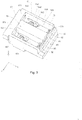
- the supply port side latching sections 220 and 230 are configured so as to function as the rotation pivot of the cartridge 20 to the holder 60 by being engaged with the supply pipe side latching section 620 when mounting the cartridge 20 on the holder 60. Accordingly, it is possible to easily perform attaching and detaching of the cartridge 20 to the holder 60.
- the distance between a side surface 225 on the +Y axial direction side and a side surface 226 on the -Y axial direction side in the supply port side latching section 220 is larger than the distance between a side surface 235 on the +Y axial direction side and a side surface 236 on the -Y axial direction side in the supply port side latching section 230. Accordingly, it is possible to prevent inclination of the cartridge 20 in the Y axial direction due to the supply port side latching section 230 without lowering operability when mounting the cartridge 20 on the holder 60 while preventing positional deviation of the cartridge 20 along the Y axis due to the supply port side latching section 220.
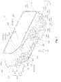
- the seventh surface 207 of the cartridge 20 is configured as a corner portion which connects between the first surface 201 and the third surface 203 along with the eighth surface 208.
- the seventh surface 207 includes a seventh surface 207a which is provided closer to the +Y axial direction and a seventh surface 207b which is provided closer to the -Y axial direction.
- a reference numeral "207" is used in cases where both the seventh surface 207a and the seventh surface 207b are being referred to.
- the wiping it is possible to remove dust and dirt which has become attached onto the cartridge side terminals 430 and reduce connection defects between the cartridge side terminals 430 and the device side terminals 730.
- the angle of the cartridge side inclined surface 408 being 40°C or less, it is possible to secure sufficient components in the +Z axial direction which are included in the pressing force Pt to the circuit board 40 from the device side terminals 730 which are provided on the terminal platform 70.
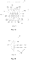
- cartridge side terminals 431 to 439 are provided on the cartridge side inclined surface 408 of the circuit board 40 as the cartridge side terminals 430 as shown in FIG. 15 .
- the number of cartridge side terminals 430 in the circuit board 40 is not limited to nine, a change to an arbitrary number is possible, and there may be nine or less or may be nine or more.
- FIG. 16 it is preferable that the cartridge side terminals 431 to 439 be the same height from the cartridge side inclined surface 408 of the circuit board 40 as each other.
- a reference numeral "430" is used in cases when all of cartridge side terminals 431 to 439 are being referred to.
- the nine cartridge side terminals 431 to 439 in the circuit board 40 are electrically connected to the control section 510 of the printer 50 via the device side terminals 730 which are provided on the terminal platform 70 of the holder 60 in the mounting state where the cartridge 20 is mounted on the holder 60. Accordingly, it enalbes the control section 510 to perform detection of the mounting of the cartridge 20 and it is possible to perform reading and writing of information to the storage device 420 of the circuit board 40.
- the cartridge side terminal 437 which functions as the grounding terminal is configured so as to come in contact with the device side terminals 730 prior to the other cartridge side terminals 431 to 436, 438, and 439 when the cartridge 20 is mounted on the holder 60. Accordingly, it is possible to reduce defects due to a high voltage using the grounding function of the cartridge side terminal 437 even in a case where a high voltage which is not intended is applied to the cartridge 20 side.
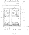
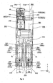
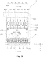
- the plurality of ink supply pipes 640 are provided on the wall section 601 of the holder as described above.
- the partition plate 607 projects between two of the ink supply pipes 640 which are adjacent to each other out of the plurality of ink supply pipes 640.
- the porous filter 644 is provided on the tip end section 642 of the ink supply pipe 640 and the elastic member 648 is provided adjacent to the ink supply pipe 640 in the wall section 601.
- the ink supply pipe 640 is provided closer to the wall section 604 (closer to the -X axial direction).
- the ink supply pipe 640 may be provided closer to the wall section 603 (closer to the +X axial direction) or may be provided on the middle of the wall section 604 and the wall section 603.
- the device side terminals 730 are provided on the device side inclined surface 708 and the device side terminals 730 on the terminal platform 70 of the holder 60 come into contact with the cartridge side terminals 430 on the circuit board 40 in the cartridge 20 when the cartridge 20 is mounted on the holder 60.
- nine device side terminals 731 to 739 are provided on the device side inclined surface 708 on the terminal platform 70 as the device side terminals 730 to correspond to the nine cartridge side terminals 431 to 439 on the circuit board 40 in the cartridge 20.
- the number of the device side terminals 730 is not limited to nine, a change to an arbitrary number is possible, and there may be nine or less or may be nine or more.
- a reference numeral "730" is used in cases when all of device side terminals 731 to 739 are being referred to.
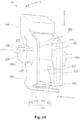
- FIG. 23 is a perspective diagram illustrating a detailed configuration of the terminal platform 70.
- FIG. 23 illustrates the terminal platform 70 removed from the holder 60.
- the nine device side terminals 731 to 739 on the terminal platform 70 are provided in positions which respectively correspond to the nine cartridge side terminals 431 to 439 on the circuit board 40 of the cartridge 20.
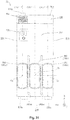
- Five device side terminals 735 to 739 are provided to line up along the Y axis on the -Z axial direction side of the device side inclined surface 708 of the terminal platform 70 and four device side terminals 731 to 734 are provided to line up along the Y axis on the +Z axial direction side of the five device side terminals 735 to 739.
- the device side terminal 737 which is positioned in the center out of the nine device side terminals 731 to 739 in the Y axial direction is a "grounding terminal" which is electrically connected to a grounding line (not shown).
- the device side terminal 737 which is the grounding terminal comes into contact with the cartridge side terminal 437 shown in FIG. 15 in a mounting state where the cartridge 20 is mounted on the holder 60.
- the height with which the device side terminal 737 protrudes from the device side inclined surface 708 is larger than that of the other device side terminals 731 to 736, 738, and 739. Accordingly, the device side terminal 737 comes into contact with the cartridge side terminals 430 (the cartridge side terminal 437) prior to the other device side terminals 731 to 736, 738, and 739.
- a pair of rotation shaft sections 850 which establish the position of the rotation center 800c is provided on the outer side surface of the pair of wall sections 860.
- the pair of rotation shaft sections 850 is provided in a position substantially in the middle of the length of the lever 80 in the Z axial direction.
- One of the pair of rotation shaft sections 850 protrudes from the surface on the -Y axial direction side of the wall section on the -Y axial direction side in the -Y axial direction and the other of the pair of rotation shaft sections 850 protrudes from the surface on the +Y axial direction side of the wall section on the +Y axial direction side in the +Y axial direction.
- the first holding member 650 includes a pair of rising sections 651 and a through hole 658.
- the engaging sections 662, 664, 665, 666, and 668 are provided on the first holding member 650.
- the pair of rising sections 651 in the first holding member 650 rise up with a gap between each other so that receiving of the lever 80 is possible.
- Shaft receiving sections 654 are provided on the pair of rising sections 651 respectively to receive the rotation shaft section 850 of the lever 80.
- engaging holes 656 are provided on the pair of rising sections 651 respectively to engage with the second holding member 680.
- the supply pipe side latching section 620 is provided on the wall section 604 of the holder 60.
- the supply pipe side latching section 620 is configured so as to be latched to the supply port side latching section 220 at the second latching position 620L which is positioned to the +Z axial direction side and the -X axial direction of the ink supply pipe 640.
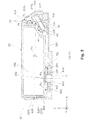
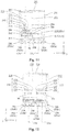
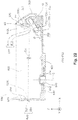
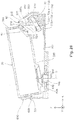
- FIG. 26 , FIG. 27 , and FIG. 28 are explanatory diagrams illustrating an attaching and detaching operation of the cartridge 20 to the holder 60.
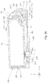
- the cartridge 20 and the holder 60 with a cross section in a position which corresponds to FIG. 5 are illustrated in FIG. 26 to FIG. 28 .
- the board side latching section 210 progresses in the -Z axial direction with movement in the Y axial direction being limited by the board side latching section 210 being guided between the pair of wall sections 860 in the lever 80 and with movement in the X axial direction being limited by the board side latching section 210 coming in contact with the flat surface 822 between the pair of wall sections 860.
- the third surface 203 side of the cartridge 20 is further rotated by being pushed.
- the board side latching section 210 is further pressed in the -Z axial direction and progresses from on the flat surface 822 of the lever 80 onto the inclined surface 824.
- the inclined surface 824 of the lever 80 comes closer to be parallel to the Z axis due to the lever 80 being rotated in a counterclockwise direction viewed from the +Y axial direction side.
- the board side latching section 210 progresses in the -Z axial direction onto the inclined surface 824 which is closer to be parallel to the Z axis.
- the abutting section 880 on a rear surface of the lever 80 abuts against the elastic member 682 and receives a pressing force, which presses to return the lever 80 in a clockwise direction viewed from the +Y axial direction, from the elastic member 682.
- the pressing force is an external force which includes components in the -Z axial direction. That is, the rotation area of the lever 80 is limited by the elastic member 682.
- a state, where the lever 80 is abutting against and is pressing the elastic member 682, is maintained from the state shown in FIG. 28 until the cartridge 20 is further pressed and the board side latching section 210 gets past the inclined surface 824 of the lever 80.
- the board side latching section 210 is provided on the third surface 203 in a position which cuts across the plane CXa but the board side latching section 210 may be provided on the third surface 203 in a position which cuts across the plane CXb or respective board side latching sections 210 may be provided on the third surface 203 in respective positions which cut across the plane CXa and the plane CXb.
- the cartridge 23 of the fourth embodiment has three ink supply ports 280.
- three ink supply ports 280 are provided on the first surface 201 of the cartridge 23 in the fourth embodiment.
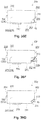
- FIG. 35 includes diagrams (A) to (C) that are explanatory diagrams illustrating a modified example of supply port side latching sections and a supply pipe side latching section 620.
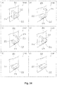
- Supply port side latching sections 220A to 220C, supply port side latching sections 230A to 230C, and supply pipe side latching sections 620A to 620C with three shapes which are different are respectively illustrated in FIG. 35(A) to FIG. 35(C) .
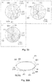
- FIGS. 36(A) to FIG. 36(H) are explanatory diagrams illustrating modified examples of an outer appearance of a cartridge. Eight modified examples which are different in terms of the outer appearance of the cartridge are each illustrated in FIGS. 36(A) to FIG. 36(H) . In the explanation of the modified examples, the same reference numerals are given to configurations which are the same as the cartridge 20 in the embodiment and the description thereof is omitted.
- the containing member 20ib of the cartridge 20i comprises a second surface 202i which is equivalent to the second surface 202 of the cartridge 20i.
- the containing member 20ib comprises a first surface 201i, a third surface 203i, a fourth surface 204i, a fifth surface 205i, a sixth surface 206i, a seventh surface 207i, and an eighth surface 208i which respectively correspond to the first surface 201 and the third to the eighth surfaces 203 to 208 of the cartridge 20i.
- the seventh surface 207i and the eighth surface 208i form connection surfaces which connect the first surface 201i and the third surface 203i.
- Two containing member side supply ports 280i are provided on the first surface 201i in order to supply ink to the two ink supply ports 280 which are provided on the adaptor 20ia.
- the foam resin bodies 284 are provided in each of the two containing member side supply ports 280i.
- a concave section 240ib for configuring the groove section 240 is provided between the two containing member side supply ports 280i.
- the concave section 240ib is provided to be concave more to the +Z axial direction side than the first surface 201i.
- the eighth surface 208i is a surface which is connected to the seventh surface 207i and the third surface 203i.
- the eighth surface 208i is an inclined surface which is inclined toward a direction which includes components in the +X axial direction and the -Z axial direction.
- the eighth surface 208i is a surface which is inclined to the first surface 201i and the third surface 203i.
- the eighth surface 208i is a surface which intersects at a right angle with the fifth surface 205i and the sixth surface 206i.
- the eighth surface 208i is inclined to the XY plane and the YZ plane and intersects at a right angle to the XZ plane.
- the slit 240ia which is provided on the first surface 201 of the adaptor 20ia and the groove section 240ib which is provided on the containing member 20ib are both provided in positions which correspond to the partition plate 607 (refer to FIG. 19 to FIG. 21 ) in the holder 60 (refer to FIG. 19 to FIG. 21 ).
- the groove section 240 is formed by combining the slit 240ia which is provided on the first surface 201 of the adaptor 20ia and the groove section 240ib which is provided on the containing member 20ib.
- the partition plate 607 (refer to FIG. 19 to FIG. 21 ) can be received in the groove section 240 when the ink supply sections 280 are connected to the ink supply pipe 640 (refer to FIG. 19 to FIG. 21 ).
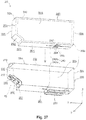
- FIG. 38 is a perspective diagram illustrating a configuration of a cartridge 20k which uses an adapter.
- the cartridge 20k is configured to be separate an adaptor 20ka and a containing member 20kb.
- the containing member 20kb has the ink containing section 290 which contains the printing material in an inner portion thereof. In a case where there is no longer any printing material in the ink containing section 290, it is possible to exchange the containing member 20kb with a new containing member 20kb or replenish the printing material in the ink containing member 290. When performing exchanging of the containing member 20kb or replenishing of the printing material, it is possible to reuse the adaptor 20ka.
- the cartridge 20k in FIG. 38 is compatible with the cartridge 20 of the first embodiment shown in FIG. 7 .
- An outer shell 200k of the cartridge 20k is configured from a combination of the outer shell of the adaptor 20ka and the outer shell of the containing member 20kb.
- the containing member 20kb has the ink containing section 290 and the ink supply port 280.
- a slit 240ka for configuring the groove section 240 is provided on the first surface 201 in a position which is equivalent to being between the two ink supply ports 280, that is, in a position which corresponds to the concave section 240kb which is provided on the first surface 201k of the containing member 20kb.
- the slit 240ka which is provided on the first surface 201 of the adaptor 20ka and the groove section 240kb which is provided on the containing member 20kb are both provided in positions which correspond to the partition plate 607 (refer to FIG. 19 to FIG 21 ) in the holder 60 (refer to FIG. 19 to FIG 21 ).
- the groove section 240 is formed by combining the slit 240ka which is provided on the first surface 201 of the adaptor 20ka and the groove section 240kb which is provided on the containing member 20kb.
- the partition plate 607 (refer to FIG. 19 to FIG 21 ) can be received in the groove section 240 when the ink supply sections 280 are connected to the ink supply pipe 640 (refer to FIG. 19 to FIG 21 ).
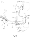
- the slit 240ma which is provided on the first surface 201 of the adaptor 20ma and the concave section or space 240mb which is provided on the auxiliary adaptor 20mS are both provided in positions which correspond to the partition plate 607 (refer to FIG. 19 to FIG 21 ) in the holder 60 (refer to FIG. 19 to FIG 21 ).
- the groove section 240 is formed by combining the slit 240ma which is provided on the first surface 201 of the adaptor 20ma and the concave section or space 240mb which is provided on the auxiliary adaptor 20mS.
- the partition plate 607 (refer to FIG. 19 to FIG 21 ) can be received in the groove section 240 when the ink supply sections 280 are connected to the ink supply pipe 640 (refer to FIG. 19 to FIG 21 ).
- the cartridge 20m in FIG. 39 can be considered to have the configuration where the adaptor 20ma and the containing member 20mb can be separated in the same manner as the cartridge 20i of FIG. 37 and the cartridge 20k of FIG. 38 .
- the external tank 20mT it is possible to exchange the external tank 20mT with a new external tank 20mT or replenish the printing material in the external tank 20mT.
- the cartridge 20m in FIG. 39 is compatible with the cartridge 20 of the first embodiment shown in FIG. 7 .
- the circuit board 40 is provided on the cartridge 20.
- the circuit board 40 need not be provided on the cartridge 20. That is, the cartridge side terminals 430 may be directly formed on the eighth surface 208. In this case, the cartridge side inclined surface 408 is a portion of the eighth surface 208.
- the surface formation of the cartridge side terminals 431 to 439 is not substantially a rectangle as with the circuit board 40 in FIG. 15 and is an irregular polygon shape.
- the surface formation of the cartridge side terminals 431 to 439 are straight line forms with a certain width and have the same formations.
- the cartridge side terminals 431 to 439 are lined up in one row in the width direction.
- the cartridge side terminals (the mounting detection terminals) 435 and 439 are respectively disposed on both sides of the arrangement of the lines of the cartridge side terminals 431 to 439.
- the cartridge side terminal (the mounting detection terminal) 431 is disposed between the cartridge side terminal (the mounting detection terminal) 435 and the cartridge side terminal (the power source terminal) 436.
- the cartridge side terminal 434 (the mounting detection terminal) is disposed between the cartridge side terminal 439 (the mounting detection terminal) and the cartridge side terminal (the data terminal) 438.
- the disposing of the contact portion cp with the device side terminals 730 which correspond to the cartridge side terminals 431 to 439 is the same as the embodiment of FIG. 15 .
- various modifications of the surface formation of each of the terminals are possible as long as the disposing of the contact portions cp is the same.
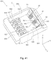
- FIG. 41 is an explanatory diagram illustrating a configuration of a holder 60A in a modified example.
- the holder 60A is the same as the holder 60 of the first embodiment excluding the point where the slot SL where the terminal platform 70 and the lever 80 are provided and the slot SL where the terminal platform 70 and the lever 80 are omitted are arranged alternately.
- the holder 60A is configured from six of the slots SL in the same manner as the holder 60 in the first embodiment and one of the ink supply pipes 640 is provided for each of the slots SL.
- the holder 60A in FIG. 41 is one example of the holder. At least one of the terminal platform 70 and the lever 80 which are not necessary with relation to the cartridge may be omitted as in the holder 60A in FIG. 41 , in another embodiment and another modified example. In addition, from the same point of view, the supply pipe side latching sections which are not necessary with relation to the cartridge may be omitted in another embodiment and another modified examples
- each type of member in the embodiment described above may be configured as independent members and a plurality of the members may be configured as an integrated member as required.
- an integrated member in the embodiment described above may be configured by combining a plurality of members.
- the invention is not limited to an ink jet printer or an ink cartridge thereof and it is possible to also apply the invention to an arbitrary liquid ejection device which ejects a liquid other than ink and a liquid containing container thereof.
- an arbitrary liquid ejection device which ejects a liquid other than ink and a liquid containing container thereof.
- the "liquid” is when a substance is in a liquid phase, and materials in a liquid state such as materials with a liquid state where the viscosity is high or low and materials with a liquid state such as sols, gel water, other inorganic solvents, organic solvents, solutions, liquid resins, and liquid metals (metal fusion liquids) are included as "liquids".
- materials in a liquid state such as materials with a liquid state where the viscosity is high or low and materials with a liquid state such as sols, gel water, other inorganic solvents, organic solvents, solutions, liquid resins, and liquid metals (metal fusion liquids) are included as "liquids”.
- liquids not only liquids as one state of a substance but where particles of a functional material which are formed as a solid material such as a pigment or metal particles are dissolved, dispersed, or mixed in a solvent are included as "liquids”.
- ink as described in the embodiments described above, liquid crystals, or the like are given as representative examples
Landscapes
- Ink Jet (AREA)
Claims (11)
- Kartusche (20), umfassend:eine erste Fläche (201) und eine zweite Fläche (202), die einander gegenüberliegen;eine dritte Fläche (203) und eine vierte Fläche (204), die sich mit der ersten Fläche (201) und der zweiten Fläche (202) schneiden und einander gegenüberliegen;eine fünfte Fläche (205) und eine sechste Fläche (206), die sich mit jeder Fläche von der ersten Fläche (201) bis zur vierten Fläche (204) schneiden und einander gegenüberliegen;einen Druckmaterial enthaltenden Abschnitt (290), der das Druckmaterial enthält;eine Vielzahl von Druckmaterial-Versorgungsanschlüssen (280), die von der ersten Fläche (201) in einer -Z-Achsenrichtung vorstehen und ein Druckmaterial aus dem Druckmaterial enthaltenden Abschnitt (290) zuführen; und gekennzeichnet durcheinen Rillenabschnitt (240), der so bereitgestellt ist, dass er in einer der -Z-Achsenrichtung entgegengesetzten -+Z-Achsenrichtung stärker konkav ist als die erste Fläche (201) und zwischen zwei der nebeneinander liegenden Druckmaterial-Versorgungsanschlüsse (280) bereitgestellt ist.
- Kartusche nach Anspruch 1, weiter umfassend
eine geneigte Fläche, die die erste Fläche (201) mit der dritten Fläche (203) verbindet und zur ersten Fläche (201) und zur dritten Fläche (203) geneigt ist;
eine Leiterplatte (40) mit kartuschenseitigen Anschlüssen (430), die auf der geneigten Fläche bereitgestellt ist; und
einen Verriegelungsabschnitt (210, 810, 220, 230), der auf mindestens einer der dritten Fläche (203) und der vierten Fläche (204) bereitgestellt ist,
wobei die Leiterplatte (40) und der Verriegelungsabschnitt (210, 810, 220, 230) an Positionen bereitgestellt sind, die eine Ebene CX schneiden, die Ebene CX durch die Mitte einer Länge einer der Vielzahl von Druckmaterial-Versorgungsanschlüssen (280) entlang einer Y-Achse verläuft, die parallel zu der Anordnung der Vielzahl von Druckmaterial-Versorgungsanschlüssen (280) ist, und die Ebene CX orthogonal zu der Y-Achse ist. - Kartusche nach Anspruch 2,
wobei der Verriegelungsabschnitt (210, 810, 220, 230) einen plattenseitigen Verriegelungsabschnitt (210) aufweist, der in einer Position bereitgestellt ist, die die Ebene CX in der dritten Fläche (203) schneidet, wobei der plattenseitige Verriegelungsabschnitt (210) eine Verriegelungsfläche aufweist, die der +Z-Achsenrichtung zugewandt ist. - Kartusche nach Anspruch 3,
wobei der plattenseitige Verriegelungsabschnitt (210) an einer an die Leiterplatte (40) angrenzenden Position bereitgestellt ist. - Kartusche nach Anspruch 2,
wobei der Verriegelungsabschnitt (210, 810, 220, 230) einen versorgungsanschlussseitigen Verriegelungsabschnitt (220, 230) einschließt, der in einer Position bereitgestellt ist, die die Ebene CX in der vierten Fläche (204) schneidet, wobei der versorgungsanschlussseitige Verriegelungsabschnitt (220, 230) eine Verriegelungsfläche aufweist, die der +Z-Achsenrichtung zugewandt ist. - Kartusche nach einem der Ansprüche 2 bis 5, weiter umfassend
einen weiteren versorgungsanschlussseitigen Verriegelungsabschnitt (220, 230), der an der vierten Fläche (204) bereitgestellt ist, wobei der weitere versorgungsanschlussseitige Verriegelungsabschnitt (220, 230) eine Verriegelungsfläche aufweist, die der +Z-Achsenrichtung zugewandt ist,
wobei der weitere versorgungsanschlussseitige Verriegelungsabschnitt (220, 230) an einer Position bereitgestellt ist, die eine weitere Ebene CX schneidet, wobei die weitere Ebene CX durch die Mitte einer Länge eines weiteren Druckmaterial-Versorgungsanschlusseses entlang einer Y-Achse verläuft und die weitere Ebene CX orthogonal zu der Y-Achse ist. - Kartusche nach Anspruch 6,
wobei der Druckmaterial-Versorgungsanschluss (280), der die Ebene CX schneidet, an einem Ende der Anordnung der Vielzahl von Druckmaterial-Versorgungsanschlüssen (280) bereitgestellt ist und
der weitere Druckmaterial-Versorgungsanschluss (280), der die weitere Ebene CX schneidet, am anderen Ende auf der Seite bereitgestellt ist, die dem einen Ende der Anordnung der Vielzahl von Druckmaterial-Versorgungsanschlüssen (280) gegenüberliegt. - Kartusche nach Anspruch 6,
wobei die Vielzahl von Druckmaterial-Versorgungsanschlüssen (280) drei oder mehr Druckmaterial-Versorgungsanschlüsse (280) einschließt,
der Druckmaterial-Versorgungsanschluss (280), der die Ebene CX schneidet, in der Mitte der Anordnung der Vielzahl von Druckmaterial-Versorgungsanschlüssen (280) bereitgestellt ist,
der weitere Druckmaterial-Versorgungsanschluss (280) zwei weitere Druckmaterial-Versorgungsanschlüsse (280) einschließt, die jeweils an beiden Enden der Anordnung der Vielzahl von Druckmaterial-Versorgungsanschlüssen (280) bereitgestellt sind, und
der weitere versorgungsöffnungsseitige Verriegelungsabschnitt (220, 230) zwei weitere versorgungsöffnungsseitige Verriegelungsabschnitte (220, 230) einschließt, wobei jeder der beiden weiteren versorgungsöffnungsseitigen Verriegelungsabschnitte (220, 230) an der Position bereitgestellt ist, die zwei der weiteren Ebenen CX schneidet. - Kartusche nach Anspruch 5, weiter umfassend
einen weiteren versorgungsanschlussseitigen Verriegelungsabschnitt (220, 230), der an der vierten Fläche (204) bereitgestellt ist, wobei der weitere versorgungsanschlussseitige Verriegelungsabschnitt (220, 230) eine Verriegelungsfläche aufweist, die der +Z-Achsenrichtung zugewandt ist,
wobei der weitere versorgungsöffnungsseitige Verriegelungsabschnitt (220, 230) an einer Position bereitgestellt ist, die eine weitere Ebene CX schneidet, die weitere Ebene CX durch die Mitte einer Länge einer weiteren der Druckmaterial-Versorgungsöffnungen (280) entlang einer Y-Achse verläuft und eine weitere Ebene CX orthogonal zu der Y-Achse ist, und
die Länge des versorgungsanschlussseitigen Verriegelungsabschnitts (220, 230) entlang der Y-Achse größer ist als die Länge des anderen versorgungsanschlussseitigen Verriegelungsabschnitts (220, 230) entlang der Y-Achse. - Kartusche nach einem der Ansprüche 2 bis 9, weiter umfassend
ein optisches Element (270), das angepasst ist, um das Druckmaterial in dem Druckmaterial enthaltenden Abschnitt (290) von der Außenseite der Patrone optisch zu erfassen,
wobei das optische Element (270) auf der ersten Fläche (201) in einer Position bereitgestellt ist, die die Ebene CX schneidet. - Druckmaterial-Versorgungssystem, umfassend:eine Druckvorrichtung; undeine Kartusche (20) nach einem der vorstehenden Ansprüche, die an der Druckvorrichtung montiert ist und der Druckvorrichtung ein Druckmaterial zuführt,wobei die Druckvorrichtung eine Vielzahl von Druckmaterial-Versorgungsleitungen (640), die so verbunden sind, dass sie jedem einer Vielzahl von Druckmaterial-Versorgungsanschlüssen (280) in der Kartusche (20) entsprechen, und eine Trennplatte, die plattenförmig zwischen zwei der nebeneinander liegenden Druckmaterial-Versorgungsleitungen (640) aus der Vielzahl von Druckmaterial-Versorgungsleitungen (640) vorsteht, einschließt unddie Trennplatte (607) in einen Rillenabschnitt (240) eingeführt wird, wenn die Kartusche (20) an der Druckvorrichtung montiert ist.
Applications Claiming Priority (1)
| Application Number | Priority Date | Filing Date | Title |
|---|---|---|---|
| JP2012152290A JP6028424B2 (ja) | 2012-07-06 | 2012-07-06 | 印刷材供給システムおよびそのカートリッジ |
Publications (3)
| Publication Number | Publication Date |
|---|---|
| EP2682270A2 EP2682270A2 (de) | 2014-01-08 |
| EP2682270A3 EP2682270A3 (de) | 2018-02-14 |
| EP2682270B1 true EP2682270B1 (de) | 2020-04-22 |
Family
ID=48703339
Family Applications (1)
| Application Number | Title | Priority Date | Filing Date |
|---|---|---|---|
| EP13175085.3A Active EP2682270B1 (de) | 2012-07-06 | 2013-07-04 | Druckmaterialzufuhrsystem und Kartusche |
Country Status (4)
| Country | Link |
|---|---|
| US (1) | US9056482B2 (de) |
| EP (1) | EP2682270B1 (de) |
| JP (1) | JP6028424B2 (de) |
| CN (2) | CN203726994U (de) |
Families Citing this family (11)
| Publication number | Priority date | Publication date | Assignee | Title |
|---|---|---|---|---|
| JP6233062B2 (ja) * | 2014-01-30 | 2017-11-22 | セイコーエプソン株式会社 | 液体供給ユニット |
| JP6202052B2 (ja) * | 2014-08-29 | 2017-09-27 | セイコーエプソン株式会社 | 液体供給ユニット |
| JP2016064532A (ja) * | 2014-09-24 | 2016-04-28 | セイコーエプソン株式会社 | 液体供給ユニット |
| JP2016187876A (ja) * | 2015-03-30 | 2016-11-04 | セイコーエプソン株式会社 | カートリッジ、カートリッジユニット、及び、液体噴射システム |
| TW201718277A (zh) * | 2015-11-27 | 2017-06-01 | Seiko Epson Corp | 液體供給單元及液體噴射裝置 |
| JP2017094660A (ja) | 2015-11-27 | 2017-06-01 | セイコーエプソン株式会社 | 液体供給ユニット |
| JP6838344B2 (ja) | 2016-10-12 | 2021-03-03 | セイコーエプソン株式会社 | 液体収容体 |
| JP2019055502A (ja) * | 2017-09-20 | 2019-04-11 | セイコーエプソン株式会社 | カートリッジ |
| JP6540772B2 (ja) * | 2017-11-02 | 2019-07-10 | セイコーエプソン株式会社 | 液体供給ユニット |
| US11334877B2 (en) | 2019-02-11 | 2022-05-17 | Bank Of America Corporation | Security tool |
| JP7533069B2 (ja) | 2020-09-25 | 2024-08-14 | セイコーエプソン株式会社 | カートリッジ、印刷システム、および、印刷装置 |
Family Cites Families (16)
| Publication number | Priority date | Publication date | Assignee | Title |
|---|---|---|---|---|
| JP3332779B2 (ja) | 1996-07-31 | 2002-10-07 | キヤノン株式会社 | インクジェット記録装置用液体収納容器 |
| JP3295339B2 (ja) * | 1996-08-30 | 2002-06-24 | キヤノン株式会社 | インクタンク、ホルダー、インクジェットカートリッジおよびキャップ |
| JP3332795B2 (ja) * | 1997-04-28 | 2002-10-07 | キヤノン株式会社 | インクタンクおよびインクジェットカートリッジ |
| EP1514689B1 (de) * | 1998-05-18 | 2006-11-08 | Seiko Epson Corporation | Tintenstrahldruckvorrichtung und zugehörige Tintenpatrone |
| US6454400B1 (en) * | 1998-09-01 | 2002-09-24 | Canon Kabushiki Kaisha | Liquid container, cartridge including liquid container, printing apparatus using cartridge and liquid discharge printing apparatus |
| JP3608397B2 (ja) * | 1998-10-06 | 2005-01-12 | セイコーエプソン株式会社 | インクカートリッジの分解方法 |
| US6302535B1 (en) * | 2000-04-19 | 2001-10-16 | Hewlett-Packard Company | Ink container configured to establish reliable electrical connection with a receiving station |
| JP4389520B2 (ja) | 2003-08-20 | 2009-12-24 | ブラザー工業株式会社 | インクジェット記録装置 |
| JP4058436B2 (ja) * | 2003-12-26 | 2008-03-12 | キヤノン株式会社 | インク収納容器 |
| JP2008100435A (ja) | 2006-10-19 | 2008-05-01 | Seiko Epson Corp | インク供給システム |
| US7810917B2 (en) * | 2006-12-21 | 2010-10-12 | Eastman Kodak Company | Printing device fluid reservoir with alignment features |
| US20080309739A1 (en) | 2007-06-14 | 2008-12-18 | Seiko Epson Corporation | Fluid supplying apparatus, fluid ejecting apparatus, and fluid supplying method |
| JP2009018566A (ja) | 2007-06-14 | 2009-01-29 | Seiko Epson Corp | 流体供給装置、流体噴射装置及び流体供給方法 |
| JP5300364B2 (ja) * | 2008-03-31 | 2013-09-25 | キヤノン株式会社 | インクタンクおよびインクジェット記録装置 |
| WO2009151436A1 (en) * | 2008-06-08 | 2009-12-17 | Hewlett-Packard Development Company, L.P. | Fluid cartridge having feature to clear bracket riser surfaces |
| JP5569475B2 (ja) * | 2010-09-03 | 2014-08-13 | セイコーエプソン株式会社 | 液体収容容器、及び、液体噴射装置 |
-
2012
- 2012-07-06 JP JP2012152290A patent/JP6028424B2/ja not_active Expired - Fee Related
-
2013
- 2013-07-04 EP EP13175085.3A patent/EP2682270B1/de active Active
- 2013-07-05 US US13/935,854 patent/US9056482B2/en not_active Expired - Fee Related
- 2013-07-08 CN CN201320403871.9U patent/CN203726994U/zh not_active Expired - Fee Related
- 2013-07-08 CN CN201310284801.0A patent/CN103522763B/zh not_active Expired - Fee Related
Non-Patent Citations (1)
| Title |
|---|
| None * |
Also Published As
| Publication number | Publication date |
|---|---|
| US9056482B2 (en) | 2015-06-16 |
| EP2682270A3 (de) | 2018-02-14 |
| CN203726994U (zh) | 2014-07-23 |
| CN103522763B (zh) | 2016-03-16 |
| US20140009539A1 (en) | 2014-01-09 |
| EP2682270A2 (de) | 2014-01-08 |
| JP6028424B2 (ja) | 2016-11-16 |
| CN103522763A (zh) | 2014-01-22 |
| JP2014014947A (ja) | 2014-01-30 |
Similar Documents
| Publication | Publication Date | Title |
|---|---|---|
| EP2682270B1 (de) | Druckmaterialzufuhrsystem und Kartusche | |
| JP7044194B2 (ja) | 印刷材供給システム | |
| CN103204005B (zh) | 盒以及印刷材料供应系统 | |
| CN104669798B (zh) | 盒和印刷材料供应系统 | |
| US9205661B2 (en) | Ink cartridge and printer | |
| JPWO2019098287A1 (ja) | カートリッジ、および、液体噴射装置 | |
| CN105383179B (zh) | 液体供应单元 | |
| JP5682732B2 (ja) | カートリッジ | |
| JP5957891B2 (ja) | カートリッジおよび印刷材供給システム | |
| CN205291939U (zh) | 液体供给单元 | |
| US8967778B2 (en) | Cartridge | |
| CN103522762B (zh) | 容器 | |
| JP5532154B2 (ja) | カートリッジおよび印刷材供給システム | |
| CN203228501U (zh) | 盒 | |
| US20190084311A1 (en) | Liquid Supply Unit | |
| JP6090418B2 (ja) | カートリッジ | |
| CN205523073U (zh) | 液体供给单元 |
Legal Events
| Date | Code | Title | Description |
|---|---|---|---|
| PUAI | Public reference made under article 153(3) epc to a published international application that has entered the european phase |
Free format text: ORIGINAL CODE: 0009012 |
|
| AK | Designated contracting states |
Kind code of ref document: A2 Designated state(s): AL AT BE BG CH CY CZ DE DK EE ES FI FR GB GR HR HU IE IS IT LI LT LU LV MC MK MT NL NO PL PT RO RS SE SI SK SM TR |
|
| AX | Request for extension of the european patent |
Extension state: BA ME |
|
| PUAL | Search report despatched |
Free format text: ORIGINAL CODE: 0009013 |
|
| AK | Designated contracting states |
Kind code of ref document: A3 Designated state(s): AL AT BE BG CH CY CZ DE DK EE ES FI FR GB GR HR HU IE IS IT LI LT LU LV MC MK MT NL NO PL PT RO RS SE SI SK SM TR |
|
| AX | Request for extension of the european patent |
Extension state: BA ME |
|
| RIC1 | Information provided on ipc code assigned before grant |
Ipc: B41J 2/175 20060101AFI20180111BHEP |
|
| STAA | Information on the status of an ep patent application or granted ep patent |
Free format text: STATUS: REQUEST FOR EXAMINATION WAS MADE |
|
| 17P | Request for examination filed |
Effective date: 20180803 |
|
| RBV | Designated contracting states (corrected) |
Designated state(s): AL AT BE BG CH CY CZ DE DK EE ES FI FR GB GR HR HU IE IS IT LI LT LU LV MC MK MT NL NO PL PT RO RS SE SI SK SM TR |
|
| GRAP | Despatch of communication of intention to grant a patent |
Free format text: ORIGINAL CODE: EPIDOSNIGR1 |
|
| STAA | Information on the status of an ep patent application or granted ep patent |
Free format text: STATUS: GRANT OF PATENT IS INTENDED |
|
| INTG | Intention to grant announced |
Effective date: 20191220 |
|
| RIN1 | Information on inventor provided before grant (corrected) |
Inventor name: NOZAWA, IZUMI Inventor name: KOBAYASHI, ATSUSHI Inventor name: MIZUTANI, TADAHIRO |
|
| GRAS | Grant fee paid |
Free format text: ORIGINAL CODE: EPIDOSNIGR3 |
|
| GRAA | (expected) grant |
Free format text: ORIGINAL CODE: 0009210 |
|
| STAA | Information on the status of an ep patent application or granted ep patent |
Free format text: STATUS: THE PATENT HAS BEEN GRANTED |
|
| AK | Designated contracting states |
Kind code of ref document: B1 Designated state(s): AL AT BE BG CH CY CZ DE DK EE ES FI FR GB GR HR HU IE IS IT LI LT LU LV MC MK MT NL NO PL PT RO RS SE SI SK SM TR |
|
| REG | Reference to a national code |
Ref country code: GB Ref legal event code: FG4D |
|
| REG | Reference to a national code |
Ref country code: CH Ref legal event code: EP |
|
| REG | Reference to a national code |
Ref country code: IE Ref legal event code: FG4D |
|
| REG | Reference to a national code |
Ref country code: DE Ref legal event code: R096 Ref document number: 602013068108 Country of ref document: DE |
|
| REG | Reference to a national code |
Ref country code: AT Ref legal event code: REF Ref document number: 1259588 Country of ref document: AT Kind code of ref document: T Effective date: 20200515 |
|
| REG | Reference to a national code |
Ref country code: LT Ref legal event code: MG4D |
|
| REG | Reference to a national code |
Ref country code: NL Ref legal event code: MP Effective date: 20200422 |
|
| PG25 | Lapsed in a contracting state [announced via postgrant information from national office to epo] |
Ref country code: FI Free format text: LAPSE BECAUSE OF FAILURE TO SUBMIT A TRANSLATION OF THE DESCRIPTION OR TO PAY THE FEE WITHIN THE PRESCRIBED TIME-LIMIT Effective date: 20200422 Ref country code: GR Free format text: LAPSE BECAUSE OF FAILURE TO SUBMIT A TRANSLATION OF THE DESCRIPTION OR TO PAY THE FEE WITHIN THE PRESCRIBED TIME-LIMIT Effective date: 20200723 Ref country code: IS Free format text: LAPSE BECAUSE OF FAILURE TO SUBMIT A TRANSLATION OF THE DESCRIPTION OR TO PAY THE FEE WITHIN THE PRESCRIBED TIME-LIMIT Effective date: 20200822 Ref country code: PT Free format text: LAPSE BECAUSE OF FAILURE TO SUBMIT A TRANSLATION OF THE DESCRIPTION OR TO PAY THE FEE WITHIN THE PRESCRIBED TIME-LIMIT Effective date: 20200824 Ref country code: NO Free format text: LAPSE BECAUSE OF FAILURE TO SUBMIT A TRANSLATION OF THE DESCRIPTION OR TO PAY THE FEE WITHIN THE PRESCRIBED TIME-LIMIT Effective date: 20200722 Ref country code: LT Free format text: LAPSE BECAUSE OF FAILURE TO SUBMIT A TRANSLATION OF THE DESCRIPTION OR TO PAY THE FEE WITHIN THE PRESCRIBED TIME-LIMIT Effective date: 20200422 Ref country code: NL Free format text: LAPSE BECAUSE OF FAILURE TO SUBMIT A TRANSLATION OF THE DESCRIPTION OR TO PAY THE FEE WITHIN THE PRESCRIBED TIME-LIMIT Effective date: 20200422 Ref country code: SE Free format text: LAPSE BECAUSE OF FAILURE TO SUBMIT A TRANSLATION OF THE DESCRIPTION OR TO PAY THE FEE WITHIN THE PRESCRIBED TIME-LIMIT Effective date: 20200422 |
|
| REG | Reference to a national code |
Ref country code: AT Ref legal event code: MK05 Ref document number: 1259588 Country of ref document: AT Kind code of ref document: T Effective date: 20200422 |
|
| PG25 | Lapsed in a contracting state [announced via postgrant information from national office to epo] |
Ref country code: HR Free format text: LAPSE BECAUSE OF FAILURE TO SUBMIT A TRANSLATION OF THE DESCRIPTION OR TO PAY THE FEE WITHIN THE PRESCRIBED TIME-LIMIT Effective date: 20200422 Ref country code: LV Free format text: LAPSE BECAUSE OF FAILURE TO SUBMIT A TRANSLATION OF THE DESCRIPTION OR TO PAY THE FEE WITHIN THE PRESCRIBED TIME-LIMIT Effective date: 20200422 Ref country code: BG Free format text: LAPSE BECAUSE OF FAILURE TO SUBMIT A TRANSLATION OF THE DESCRIPTION OR TO PAY THE FEE WITHIN THE PRESCRIBED TIME-LIMIT Effective date: 20200722 Ref country code: RS Free format text: LAPSE BECAUSE OF FAILURE TO SUBMIT A TRANSLATION OF THE DESCRIPTION OR TO PAY THE FEE WITHIN THE PRESCRIBED TIME-LIMIT Effective date: 20200422 |
|
| PG25 | Lapsed in a contracting state [announced via postgrant information from national office to epo] |
Ref country code: AL Free format text: LAPSE BECAUSE OF FAILURE TO SUBMIT A TRANSLATION OF THE DESCRIPTION OR TO PAY THE FEE WITHIN THE PRESCRIBED TIME-LIMIT Effective date: 20200422 |
|
| REG | Reference to a national code |
Ref country code: DE Ref legal event code: R097 Ref document number: 602013068108 Country of ref document: DE |
|
| PG25 | Lapsed in a contracting state [announced via postgrant information from national office to epo] |
Ref country code: ES Free format text: LAPSE BECAUSE OF FAILURE TO SUBMIT A TRANSLATION OF THE DESCRIPTION OR TO PAY THE FEE WITHIN THE PRESCRIBED TIME-LIMIT Effective date: 20200422 Ref country code: CZ Free format text: LAPSE BECAUSE OF FAILURE TO SUBMIT A TRANSLATION OF THE DESCRIPTION OR TO PAY THE FEE WITHIN THE PRESCRIBED TIME-LIMIT Effective date: 20200422 Ref country code: RO Free format text: LAPSE BECAUSE OF FAILURE TO SUBMIT A TRANSLATION OF THE DESCRIPTION OR TO PAY THE FEE WITHIN THE PRESCRIBED TIME-LIMIT Effective date: 20200422 Ref country code: EE Free format text: LAPSE BECAUSE OF FAILURE TO SUBMIT A TRANSLATION OF THE DESCRIPTION OR TO PAY THE FEE WITHIN THE PRESCRIBED TIME-LIMIT Effective date: 20200422 Ref country code: IT Free format text: LAPSE BECAUSE OF FAILURE TO SUBMIT A TRANSLATION OF THE DESCRIPTION OR TO PAY THE FEE WITHIN THE PRESCRIBED TIME-LIMIT Effective date: 20200422 Ref country code: AT Free format text: LAPSE BECAUSE OF FAILURE TO SUBMIT A TRANSLATION OF THE DESCRIPTION OR TO PAY THE FEE WITHIN THE PRESCRIBED TIME-LIMIT Effective date: 20200422 Ref country code: SM Free format text: LAPSE BECAUSE OF FAILURE TO SUBMIT A TRANSLATION OF THE DESCRIPTION OR TO PAY THE FEE WITHIN THE PRESCRIBED TIME-LIMIT Effective date: 20200422 Ref country code: DK Free format text: LAPSE BECAUSE OF FAILURE TO SUBMIT A TRANSLATION OF THE DESCRIPTION OR TO PAY THE FEE WITHIN THE PRESCRIBED TIME-LIMIT Effective date: 20200422 |
|
| PG25 | Lapsed in a contracting state [announced via postgrant information from national office to epo] |
Ref country code: MC Free format text: LAPSE BECAUSE OF FAILURE TO SUBMIT A TRANSLATION OF THE DESCRIPTION OR TO PAY THE FEE WITHIN THE PRESCRIBED TIME-LIMIT Effective date: 20200422 Ref country code: SK Free format text: LAPSE BECAUSE OF FAILURE TO SUBMIT A TRANSLATION OF THE DESCRIPTION OR TO PAY THE FEE WITHIN THE PRESCRIBED TIME-LIMIT Effective date: 20200422 Ref country code: PL Free format text: LAPSE BECAUSE OF FAILURE TO SUBMIT A TRANSLATION OF THE DESCRIPTION OR TO PAY THE FEE WITHIN THE PRESCRIBED TIME-LIMIT Effective date: 20200422 |
|
| PLBE | No opposition filed within time limit |
Free format text: ORIGINAL CODE: 0009261 |
|
| REG | Reference to a national code |
Ref country code: CH Ref legal event code: PL |
|
| STAA | Information on the status of an ep patent application or granted ep patent |
Free format text: STATUS: NO OPPOSITION FILED WITHIN TIME LIMIT |
|
| 26N | No opposition filed |
Effective date: 20210125 |
|
| REG | Reference to a national code |
Ref country code: BE Ref legal event code: MM Effective date: 20200731 |
|
| PG25 | Lapsed in a contracting state [announced via postgrant information from national office to epo] |
Ref country code: CH Free format text: LAPSE BECAUSE OF NON-PAYMENT OF DUE FEES Effective date: 20200731 Ref country code: IE Free format text: LAPSE BECAUSE OF NON-PAYMENT OF DUE FEES Effective date: 20200704 Ref country code: LI Free format text: LAPSE BECAUSE OF NON-PAYMENT OF DUE FEES Effective date: 20200731 Ref country code: LU Free format text: LAPSE BECAUSE OF NON-PAYMENT OF DUE FEES Effective date: 20200704 |
|
| PG25 | Lapsed in a contracting state [announced via postgrant information from national office to epo] |
Ref country code: BE Free format text: LAPSE BECAUSE OF NON-PAYMENT OF DUE FEES Effective date: 20200731 Ref country code: SI Free format text: LAPSE BECAUSE OF FAILURE TO SUBMIT A TRANSLATION OF THE DESCRIPTION OR TO PAY THE FEE WITHIN THE PRESCRIBED TIME-LIMIT Effective date: 20200422 |
|
| PGFP | Annual fee paid to national office [announced via postgrant information from national office to epo] |
Ref country code: FR Payment date: 20210611 Year of fee payment: 9 |
|
| PGFP | Annual fee paid to national office [announced via postgrant information from national office to epo] |
Ref country code: GB Payment date: 20210609 Year of fee payment: 9 |
|
| PGFP | Annual fee paid to national office [announced via postgrant information from national office to epo] |
Ref country code: DE Payment date: 20210608 Year of fee payment: 9 |
|
| PG25 | Lapsed in a contracting state [announced via postgrant information from national office to epo] |
Ref country code: TR Free format text: LAPSE BECAUSE OF FAILURE TO SUBMIT A TRANSLATION OF THE DESCRIPTION OR TO PAY THE FEE WITHIN THE PRESCRIBED TIME-LIMIT Effective date: 20200422 Ref country code: MT Free format text: LAPSE BECAUSE OF FAILURE TO SUBMIT A TRANSLATION OF THE DESCRIPTION OR TO PAY THE FEE WITHIN THE PRESCRIBED TIME-LIMIT Effective date: 20200422 Ref country code: CY Free format text: LAPSE BECAUSE OF FAILURE TO SUBMIT A TRANSLATION OF THE DESCRIPTION OR TO PAY THE FEE WITHIN THE PRESCRIBED TIME-LIMIT Effective date: 20200422 |
|
| PG25 | Lapsed in a contracting state [announced via postgrant information from national office to epo] |
Ref country code: MK Free format text: LAPSE BECAUSE OF FAILURE TO SUBMIT A TRANSLATION OF THE DESCRIPTION OR TO PAY THE FEE WITHIN THE PRESCRIBED TIME-LIMIT Effective date: 20200422 |
|
| REG | Reference to a national code |
Ref country code: DE Ref legal event code: R119 Ref document number: 602013068108 Country of ref document: DE |
|
| GBPC | Gb: european patent ceased through non-payment of renewal fee |
Effective date: 20220704 |
|
| PG25 | Lapsed in a contracting state [announced via postgrant information from national office to epo] |
Ref country code: FR Free format text: LAPSE BECAUSE OF NON-PAYMENT OF DUE FEES Effective date: 20220731 |
|
| PG25 | Lapsed in a contracting state [announced via postgrant information from national office to epo] |
Ref country code: GB Free format text: LAPSE BECAUSE OF NON-PAYMENT OF DUE FEES Effective date: 20220704 Ref country code: DE Free format text: LAPSE BECAUSE OF NON-PAYMENT OF DUE FEES Effective date: 20230201 |