EP2682293B1 - Boite de vitesses robotisée avec moteur à explosion et machine électrique - Google Patents
Boite de vitesses robotisée avec moteur à explosion et machine électrique Download PDFInfo
- Publication number
- EP2682293B1 EP2682293B1 EP13174989.7A EP13174989A EP2682293B1 EP 2682293 B1 EP2682293 B1 EP 2682293B1 EP 13174989 A EP13174989 A EP 13174989A EP 2682293 B1 EP2682293 B1 EP 2682293B1
- Authority
- EP
- European Patent Office
- Prior art keywords
- gear
- shaft
- gearbox
- manual transmission
- automatic manual
- Prior art date
- Legal status (The legal status is an assumption and is not a legal conclusion. Google has not performed a legal analysis and makes no representation as to the accuracy of the status listed.)
- Active
Links
Images


Classifications
-
- B—PERFORMING OPERATIONS; TRANSPORTING
- B60—VEHICLES IN GENERAL
- B60W—CONJOINT CONTROL OF VEHICLE SUB-UNITS OF DIFFERENT TYPE OR DIFFERENT FUNCTION; CONTROL SYSTEMS SPECIALLY ADAPTED FOR HYBRID VEHICLES; ROAD VEHICLE DRIVE CONTROL SYSTEMS FOR PURPOSES NOT RELATED TO THE CONTROL OF A PARTICULAR SUB-UNIT
- B60W20/00—Control systems specially adapted for hybrid vehicles
- B60W20/30—Control strategies involving selection of transmission gear ratio
-
- B—PERFORMING OPERATIONS; TRANSPORTING
- B60—VEHICLES IN GENERAL
- B60K—ARRANGEMENT OR MOUNTING OF PROPULSION UNITS OR OF TRANSMISSIONS IN VEHICLES; ARRANGEMENT OR MOUNTING OF PLURAL DIVERSE PRIME-MOVERS IN VEHICLES; AUXILIARY DRIVES FOR VEHICLES; INSTRUMENTATION OR DASHBOARDS FOR VEHICLES; ARRANGEMENTS IN CONNECTION WITH COOLING, AIR INTAKE, GAS EXHAUST OR FUEL SUPPLY OF PROPULSION UNITS IN VEHICLES
- B60K6/00—Arrangement or mounting of plural diverse prime-movers for mutual or common propulsion, e.g. hybrid propulsion systems comprising electric motors and internal combustion engines
- B60K6/20—Arrangement or mounting of plural diverse prime-movers for mutual or common propulsion, e.g. hybrid propulsion systems comprising electric motors and internal combustion engines the prime-movers consisting of electric motors and internal combustion engines, e.g. HEVs
- B60K6/22—Arrangement or mounting of plural diverse prime-movers for mutual or common propulsion, e.g. hybrid propulsion systems comprising electric motors and internal combustion engines the prime-movers consisting of electric motors and internal combustion engines, e.g. HEVs characterised by apparatus, components or means specially adapted for HEVs
- B60K6/38—Arrangement or mounting of plural diverse prime-movers for mutual or common propulsion, e.g. hybrid propulsion systems comprising electric motors and internal combustion engines the prime-movers consisting of electric motors and internal combustion engines, e.g. HEVs characterised by apparatus, components or means specially adapted for HEVs characterised by the driveline clutches
- B60K6/383—One-way clutches or freewheel devices
-
- B—PERFORMING OPERATIONS; TRANSPORTING
- B60—VEHICLES IN GENERAL
- B60K—ARRANGEMENT OR MOUNTING OF PROPULSION UNITS OR OF TRANSMISSIONS IN VEHICLES; ARRANGEMENT OR MOUNTING OF PLURAL DIVERSE PRIME-MOVERS IN VEHICLES; AUXILIARY DRIVES FOR VEHICLES; INSTRUMENTATION OR DASHBOARDS FOR VEHICLES; ARRANGEMENTS IN CONNECTION WITH COOLING, AIR INTAKE, GAS EXHAUST OR FUEL SUPPLY OF PROPULSION UNITS IN VEHICLES
- B60K6/00—Arrangement or mounting of plural diverse prime-movers for mutual or common propulsion, e.g. hybrid propulsion systems comprising electric motors and internal combustion engines
- B60K6/20—Arrangement or mounting of plural diverse prime-movers for mutual or common propulsion, e.g. hybrid propulsion systems comprising electric motors and internal combustion engines the prime-movers consisting of electric motors and internal combustion engines, e.g. HEVs
- B60K6/22—Arrangement or mounting of plural diverse prime-movers for mutual or common propulsion, e.g. hybrid propulsion systems comprising electric motors and internal combustion engines the prime-movers consisting of electric motors and internal combustion engines, e.g. HEVs characterised by apparatus, components or means specially adapted for HEVs
- B60K6/38—Arrangement or mounting of plural diverse prime-movers for mutual or common propulsion, e.g. hybrid propulsion systems comprising electric motors and internal combustion engines the prime-movers consisting of electric motors and internal combustion engines, e.g. HEVs characterised by apparatus, components or means specially adapted for HEVs characterised by the driveline clutches
- B60K6/387—Actuated clutches, i.e. clutches engaged or disengaged by electric, hydraulic or mechanical actuating means
-
- B—PERFORMING OPERATIONS; TRANSPORTING
- B60—VEHICLES IN GENERAL
- B60K—ARRANGEMENT OR MOUNTING OF PROPULSION UNITS OR OF TRANSMISSIONS IN VEHICLES; ARRANGEMENT OR MOUNTING OF PLURAL DIVERSE PRIME-MOVERS IN VEHICLES; AUXILIARY DRIVES FOR VEHICLES; INSTRUMENTATION OR DASHBOARDS FOR VEHICLES; ARRANGEMENTS IN CONNECTION WITH COOLING, AIR INTAKE, GAS EXHAUST OR FUEL SUPPLY OF PROPULSION UNITS IN VEHICLES
- B60K6/00—Arrangement or mounting of plural diverse prime-movers for mutual or common propulsion, e.g. hybrid propulsion systems comprising electric motors and internal combustion engines
- B60K6/20—Arrangement or mounting of plural diverse prime-movers for mutual or common propulsion, e.g. hybrid propulsion systems comprising electric motors and internal combustion engines the prime-movers consisting of electric motors and internal combustion engines, e.g. HEVs
- B60K6/42—Arrangement or mounting of plural diverse prime-movers for mutual or common propulsion, e.g. hybrid propulsion systems comprising electric motors and internal combustion engines the prime-movers consisting of electric motors and internal combustion engines, e.g. HEVs characterised by the architecture of the hybrid electric vehicle
- B60K6/48—Parallel type
- B60K2006/4808—Electric machine connected or connectable to gearbox output shaft
-
- B—PERFORMING OPERATIONS; TRANSPORTING
- B60—VEHICLES IN GENERAL
- B60K—ARRANGEMENT OR MOUNTING OF PROPULSION UNITS OR OF TRANSMISSIONS IN VEHICLES; ARRANGEMENT OR MOUNTING OF PLURAL DIVERSE PRIME-MOVERS IN VEHICLES; AUXILIARY DRIVES FOR VEHICLES; INSTRUMENTATION OR DASHBOARDS FOR VEHICLES; ARRANGEMENTS IN CONNECTION WITH COOLING, AIR INTAKE, GAS EXHAUST OR FUEL SUPPLY OF PROPULSION UNITS IN VEHICLES
- B60K6/00—Arrangement or mounting of plural diverse prime-movers for mutual or common propulsion, e.g. hybrid propulsion systems comprising electric motors and internal combustion engines
- B60K6/20—Arrangement or mounting of plural diverse prime-movers for mutual or common propulsion, e.g. hybrid propulsion systems comprising electric motors and internal combustion engines the prime-movers consisting of electric motors and internal combustion engines, e.g. HEVs
- B60K6/42—Arrangement or mounting of plural diverse prime-movers for mutual or common propulsion, e.g. hybrid propulsion systems comprising electric motors and internal combustion engines the prime-movers consisting of electric motors and internal combustion engines, e.g. HEVs characterised by the architecture of the hybrid electric vehicle
- B60K6/48—Parallel type
- B60K2006/4825—Electric machine connected or connectable to gearbox input shaft
-
- B—PERFORMING OPERATIONS; TRANSPORTING
- B60—VEHICLES IN GENERAL
- B60K—ARRANGEMENT OR MOUNTING OF PROPULSION UNITS OR OF TRANSMISSIONS IN VEHICLES; ARRANGEMENT OR MOUNTING OF PLURAL DIVERSE PRIME-MOVERS IN VEHICLES; AUXILIARY DRIVES FOR VEHICLES; INSTRUMENTATION OR DASHBOARDS FOR VEHICLES; ARRANGEMENTS IN CONNECTION WITH COOLING, AIR INTAKE, GAS EXHAUST OR FUEL SUPPLY OF PROPULSION UNITS IN VEHICLES
- B60K6/00—Arrangement or mounting of plural diverse prime-movers for mutual or common propulsion, e.g. hybrid propulsion systems comprising electric motors and internal combustion engines
- B60K6/20—Arrangement or mounting of plural diverse prime-movers for mutual or common propulsion, e.g. hybrid propulsion systems comprising electric motors and internal combustion engines the prime-movers consisting of electric motors and internal combustion engines, e.g. HEVs
- B60K6/42—Arrangement or mounting of plural diverse prime-movers for mutual or common propulsion, e.g. hybrid propulsion systems comprising electric motors and internal combustion engines the prime-movers consisting of electric motors and internal combustion engines, e.g. HEVs characterised by the architecture of the hybrid electric vehicle
- B60K6/48—Parallel type
- B60K2006/4833—Step up or reduction gearing driving generator, e.g. to operate generator in most efficient speed range
- B60K2006/4841—Step up or reduction gearing driving generator, e.g. to operate generator in most efficient speed range the gear provides shifting between multiple ratios
-
- B—PERFORMING OPERATIONS; TRANSPORTING
- B60—VEHICLES IN GENERAL
- B60K—ARRANGEMENT OR MOUNTING OF PROPULSION UNITS OR OF TRANSMISSIONS IN VEHICLES; ARRANGEMENT OR MOUNTING OF PLURAL DIVERSE PRIME-MOVERS IN VEHICLES; AUXILIARY DRIVES FOR VEHICLES; INSTRUMENTATION OR DASHBOARDS FOR VEHICLES; ARRANGEMENTS IN CONNECTION WITH COOLING, AIR INTAKE, GAS EXHAUST OR FUEL SUPPLY OF PROPULSION UNITS IN VEHICLES
- B60K6/00—Arrangement or mounting of plural diverse prime-movers for mutual or common propulsion, e.g. hybrid propulsion systems comprising electric motors and internal combustion engines
- B60K6/20—Arrangement or mounting of plural diverse prime-movers for mutual or common propulsion, e.g. hybrid propulsion systems comprising electric motors and internal combustion engines the prime-movers consisting of electric motors and internal combustion engines, e.g. HEVs
- B60K6/50—Architecture of the driveline characterised by arrangement or kind of transmission units
- B60K6/54—Transmission for changing ratio
- B60K2006/541—Transmission for changing ratio without reverse ratio using instead electric reversing
-
- F—MECHANICAL ENGINEERING; LIGHTING; HEATING; WEAPONS; BLASTING
- F16—ENGINEERING ELEMENTS AND UNITS; GENERAL MEASURES FOR PRODUCING AND MAINTAINING EFFECTIVE FUNCTIONING OF MACHINES OR INSTALLATIONS; THERMAL INSULATION IN GENERAL
- F16H—GEARING
- F16H37/00—Combinations of mechanical gearings, not provided for in groups F16H1/00 - F16H35/00
- F16H37/02—Combinations of mechanical gearings, not provided for in groups F16H1/00 - F16H35/00 comprising essentially only toothed or friction gearings
- F16H37/04—Combinations of toothed gearings only
- F16H37/042—Combinations of toothed gearings only change gear transmissions in group arrangement
- F16H37/043—Combinations of toothed gearings only change gear transmissions in group arrangement without gears having orbital motion
- F16H2037/045—Combinations of toothed gearings only change gear transmissions in group arrangement without gears having orbital motion comprising a separate gearing unit for shifting between high and low ratio range
-
- F—MECHANICAL ENGINEERING; LIGHTING; HEATING; WEAPONS; BLASTING
- F16—ENGINEERING ELEMENTS AND UNITS; GENERAL MEASURES FOR PRODUCING AND MAINTAINING EFFECTIVE FUNCTIONING OF MACHINES OR INSTALLATIONS; THERMAL INSULATION IN GENERAL
- F16H—GEARING
- F16H2200/00—Transmissions for multiple ratios
- F16H2200/003—Transmissions for multiple ratios characterised by the number of forward speeds
- F16H2200/006—Transmissions for multiple ratios characterised by the number of forward speeds the gear ratios comprising eight forward speeds
-
- Y—GENERAL TAGGING OF NEW TECHNOLOGICAL DEVELOPMENTS; GENERAL TAGGING OF CROSS-SECTIONAL TECHNOLOGIES SPANNING OVER SEVERAL SECTIONS OF THE IPC; TECHNICAL SUBJECTS COVERED BY FORMER USPC CROSS-REFERENCE ART COLLECTIONS [XRACs] AND DIGESTS
- Y02—TECHNOLOGIES OR APPLICATIONS FOR MITIGATION OR ADAPTATION AGAINST CLIMATE CHANGE
- Y02T—CLIMATE CHANGE MITIGATION TECHNOLOGIES RELATED TO TRANSPORTATION
- Y02T10/00—Road transport of goods or passengers
- Y02T10/60—Other road transportation technologies with climate change mitigation effect
- Y02T10/62—Hybrid vehicles
-
- Y—GENERAL TAGGING OF NEW TECHNOLOGICAL DEVELOPMENTS; GENERAL TAGGING OF CROSS-SECTIONAL TECHNOLOGIES SPANNING OVER SEVERAL SECTIONS OF THE IPC; TECHNICAL SUBJECTS COVERED BY FORMER USPC CROSS-REFERENCE ART COLLECTIONS [XRACs] AND DIGESTS
- Y10—TECHNICAL SUBJECTS COVERED BY FORMER USPC
- Y10S—TECHNICAL SUBJECTS COVERED BY FORMER USPC CROSS-REFERENCE ART COLLECTIONS [XRACs] AND DIGESTS
- Y10S903/00—Hybrid electric vehicles, HEVS
- Y10S903/902—Prime movers comprising electrical and internal combustion motors
Definitions
- the present invention relates to an automatic manual transmission for a hybrid car provided with an internal combustion engine and with an electrical machine.
- the automatic manual transmission comprises a mechanical gearbox provided with a primary shaft, a secondary shaft, a plurality of pairs of gears, and a plurality of servo-assisted locking devices activated by first actuators.
- the automatic manual transmission comprises a servo-assisted drive device with a variable gear ratio, which is interposed between a drive shaft originating from the internal combustion engine and the primary shaft and can be adjusted so as to present two different gear ratios: a first even direct drive gear ratio and a second increased gear ratio.
- the automatic manual transmission comprises a second actuator, which is coupled to the drive device, so as to vary the gear ratio of the drive device.
- a control unit controls, in a coordinated manner, the first actuators and the second actuator so as to combine a gear ratio of the drive device with a gear ratio of the gearbox to obtain a corresponding gear.
- Patent Application US2011167956 describes an automatic manual hybrid transmission.
- a single-clutch gearbox is provided and the shaft of the electrical machine is directly connected to the secondary shaft of the gearbox.
- a twin-clutch gearbox is provided, provided with one primary shaft and two secondary shafts and the shaft of the electrical machine can be connected to both the secondary shafts of the gearbox by means of one gear train.
- Patent Application DE102008031456A1 discloses a powershift transmission for use in drive train of car for drive application and having an upstream transmission including a shaft, which stays in connection with a drive shaft by fixed transmission and is connected with a support shaft.
- Patent Application EP2447571A1 discloses a transmission for a hybrid vehicle including a single planetary gear.
- the object of the present invention is to provide an automatic manual transmission for a hybrid car provided with an internal combustion engine and with an electrical machine, the automatic manual transmission of which is exempt from the above-described drawbacks, is simple and affordable to implement, and in particular allows the electrical machine to effectively perform different functions in an energetically efficient manner.
- an automatic manual transmission is provided for a hybrid car provided with an internal combustion engine and an electrical machine, as claimed by the appended claims.
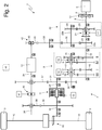
- Numeral 1 in figure 1 indicates a road vehicle as a whole, provided with two front wheels 2 and two rear driving wheels 3, which receive the torque from a motor propulsion system 4.
- the motor propulsion system 4 comprises an internal combustion heat engine 5, which is arranged in front longitudinal position and is provided with a crankshaft 6, and an automatic manual transmission 7 (commonly called "AMT"), which transmits the torque generated by the internal combustion engine 5 to the rear driving wheels 3, and presents the configuration referred to as "transaxle".
- Transmission 7 comprises a drive shaft 8 which on the one hand is connected to the crankshaft 6 and on the other hand is mechanically connected to a gearbox 9, which is arranged in rear longitudinal position, and transmits the motion to the rear driving wheels 3 by means of two axle shafts 10.
- Gearbox 9 is also coupled to a clutch 11, which is also arranged in rear position and is housed in a bell fixed to the casing of gearbox 9.
- the motor propulsion system 4 comprises an electrical machine 12, which may be controlled to operate as a generator (by absorbing mechanical energy and supplying electric energy) or as an engine (by absorbing electric energy and supplying mechanical energy).
- the engine of the internal combustion engine 5 is provided with a flywheel 13 (typically a cushioned double flywheel) which is interposed between the crankshaft 6 and the drive shaft 8.
- a flywheel 13 typically a cushioned double flywheel
- Gearbox 9 comprises a primary shaft 14, a secondary shaft 15, which is arranged parallel to and beside the primary shaft 14, and has a plurality of pairs (indicated with the Roman numerals I, II, III, IV) of gears 16 and 17, each of which has a corresponding gear ratio and comprises a primary gear 16, which is mounted rigidly on the primary shaft 14, and a secondary gear 17, which is mounted idle on the secondary shaft 15 and meshes, in a permanent manner, with the primary gear 16.
- gearbox 9 comprises a pair of locking devices 18, each of which is mounted on the secondary shaft 15 and is suited to be actuated so as to alternatively lock two corresponding secondary gears 17 to the secondary shaft 15.
- the primary gears 16 are mounted idle on the primary shaft 14, the secondary gears 17 are mounted rigidly on the secondary shaft 15, and the two servo-assisted locking devices 18 are mounted coaxial to the primary shaft 14 to lock, in an alternative manner, the corresponding primary gears 16 to the primary shaft 14.
- Each locking device 18 is servo-assisted, i.e. is mechanically coupled to an actuator 19 (hydraulic or electric) which acts on the locking device 18 to move the locking device 18 between an intermediate idle position, in which the locking device 18 does not lock any secondary gear 17 to the secondary shaft 15, and two locking positions, in each of which the locking device 18 locks a corresponding secondary gear 17 to the secondary shaft 15.
- actuator 19 hydraulic or electric
- the automatic manual transmission 7 comprises a drive device 20 with a variable gear ratio, which can be adjusted so as to present two different gear ratios and is interposed between the drive shaft 8 and the primary shaft 14; in other words, an input of the drive device 20 is integral to the drive shaft 8 (i.e. is rigidly restrained to the end of the drive shaft 8 opposite to the end which is integral to the flywheel 13), and an output of the drive device 20 is integral to the primary shaft 14 (i.e. is rigidly restrained to one end of the primary shaft 14).
- the drive device 20 can be adjusted to present an even gear ratio (i.e.
- the drive device 20 can be adjusted to present an increased gear ratio (i.e. a gear ratio greater than 1:1 by means of which the primary shaft 14 rotates faster than the drive shaft 8).
- the drive device 20 comprises a locking device 21 which is suited to be actuated so as to alternatively engage two different paths for the motion: a direct drive path (gear ratio 1:1) and an increased path (gear ratio greater than 1:1); the two paths extend by means of two parallel shafts 22a and 22b, which are connected to each other upstream of and downstream of the locking device 21 through two corresponding pairs of gears (moreover, shaft 22a is integral to the primary shaft 14 of gearbox 9).
- the pair of gears arranged upstream of the locking device 21 comprises a gear wheel 23 which is mounted idle on the drive shaft 8 and is locked to the drive shaft 8 by the locking device 21 and a gear wheel 24 which is integral to shaft 22b and meshes with the gear wheel 23;
- the pair of gears arranged downstream of the locking device 21 comprises a gear wheel 25 which is integral to shaft 22a and a gear wheel 26 which is integral to shaft 22b and meshes with the gear wheel 25.
- the locking device 21 alternatively locks the gear wheel 23 to the drive shaft 8 or locks the drive shaft 8 in direct drive to shaft 22a.
- the drive device 20 is servo-assisted, i.e. is mechanically coupled to an actuator 27 (hydraulic or electric) which acts on the locking device 21 to alternatively select the even gear ratio (with which the primary shaft 14 presents the same angular speed as the drive shaft 8) or the increased gear ratio (with which the primary shaft 14 rotates faster than the drive shaft 8).
- an actuator 27 hydraulic or electric
- Clutch 11 is arranged downstream of gearbox 9 and is interposed between the secondary shaft 15 of gearbox 9 and a differential gear 28 to which the axle shafts 10 are directly connected.
- Clutch 11 presents an input shaft 29 which is connected to the secondary shaft 15 of gearbox 9 through a pair of gears; in particular, one gear wheel 30 is integral to the secondary shaft 15 and one gear wheel 31 is integral to the input shaft 29 and meshes with the gear wheel 30.
- clutch 11 presents an output shaft 32 which is directly connected to the differential gear 28.
- Clutch 11 is servo-assisted, i.e.
- clutch 11 is mechanically coupled to an actuator 33 (hydraulic or electric) which acts on clutch 11 to move clutch 11 between an open position (in which clutch 11 separates the input shaft 29 from the output shaft 32 and therefore separates the secondary shaft 15 of gearbox 9 from the rear driving wheels 3) and a closed position (in which clutch 11 connects the input shaft 29 and the output shaft 32 to each other and therefore connects the secondary shaft 15 of gearbox 9 and the rear driving wheels 3 to each other).
- the servo-assisted clutch 11 can be opened to interrupt the mechanical connection between the input shaft 29 and the output shaft 32 and therefore to interrupt the mechanical connection between the secondary shaft 15 of gearbox 9 and the rear driving wheels 3.
- the automatic manual transmission 7 comprises an auxiliary shaft 34, along which the electrical machine 12 is mounted; in other words, the auxiliary shaft 34 passes through the electrical machine 12 which is therefore crossed from side to side by the auxiliary shaft 34.
- the auxiliary shaft 34 may be monolithic (that is made in one piece without joints) or may consist of several components joined to each other at a head.
- auxiliary shaft 34 arranged upstream of the electrical machine 12 is mechanically connected with the primary shaft 14 of gearbox 9 through a gear train, which comprises a gear wheel which is mechanically connected to the auxiliary shaft 34 and a gear wheel 36 which on one side meshes with the gear wheel 35 and on the other side meshes with the gear wheel 26 of the drive device 20; as previously mentioned, the gear wheel 26 of the drive device 20 meshes with the gear wheel 27 of the drive device 20 which is angularly integral to the primary shaft 14 of gearbox 9.
- One end of the auxiliary shaft 34 arranged downstream of the electrical machine 12 can be connected alternatively to the input shaft 29 of clutch 11 (which is angularly integral to the secondary shaft 15 of gearbox 9) or to the output shaft 32 of clutch 11 (which is angularly integral to the differential gear 28).
- the end of the auxiliary shaft 34 arranged downstream of the electrical machine 12 is provided with a gear wheel 37, which is mounted idle on the auxiliary shaft 34 and meshes with the gear wheel 31 which, in turn, is splined to the input shaft 29 of clutch 11 and is angularly integral to the secondary shaft 15 of gearbox 9 thus meshing with the gear wheel 30.
- the end of the auxiliary shaft 34 arranged downstream of the electrical machine 12 is provided with a gear wheel 38, which is mounted idle on the auxiliary shaft 34 and meshes with the gear wheel 39 which is integral to the output shaft 32 of clutch 11.
- a locking device 40 is provided, which is mounted on the auxiliary shaft 34 and is suited to be actuated so as to alternatively lock the two gear wheels 37 and 38 to the auxiliary shaft 34.
- the locking device 40 is servo-assisted, i.e. is mechanically coupled to an actuator 41 (hydraulic or electric) which acts on the locking device 40 to move the locking device 40 between an intermediate idle position, in which the locking device 40 does not lock any gear wheel 37 or 38 to the auxiliary shaft 34, and two locking positions, in each of which the locking device 40 locks a corresponding gear wheel 37 or 38 to the auxiliary shaft 34.
- an actuator 41 hydraulic or electric
- the end of the auxiliary shaft 34 arranged upstream of the electrical machine 12 is provided with a disconnecting device 42, which is suited to separate the auxiliary shaft 34 from the primary shaft 14 of gearbox 9 (or better, by separating the auxiliary shaft 34 from the gear train which connects the auxiliary shaft 34 to the primary shaft 14 of gearbox 9).
- the disconnecting device 42 is passive (i.e. it cannot be controlled) and comprises a freewheel 43 (or idle wheel 43) which transmits the motion (i.e. meshes) when it rotates in a certain rotating direction and does not transmit the motion (i.e. it does not mesh) when it rotates in the opposite rotating direction.
- freewheel 43 presents the centrifugal disconnection which allows the transmission of the motion (i.e. allows meshing) only when the rotation speed is lower than a predetermined maximum rotation speed.
- the disconnecting device 42 is active (i.e. can be controlled) and comprises a clutch 44 which may be opened and closed when wanted.
- Clutch 44 is servo-assisted, i.e. is mechanically coupled to an actuator 45 (hydraulic or electric) which acts on clutch 44 to move clutch 44 between an open position (in which clutch 44 separates the auxiliary shaft 34 from the gear wheel 35) and a closed position (in which clutch 44 connects the auxiliary shaft 34 and the gear wheel 35 to each other).
- the function of the disconnecting device 42 is to mechanically disconnect the electrical machine 12 from the primary shaft 14 of gearbox 9 (and therefore also from crankshaft 6 of the internal combustion engine 5) in certain operating modes and/or when the electrical machine 12 reaches rotation speeds which are too high (i.e. cannot be mechanically supported by the electrical machine 12 especially for long periods).
- the automatic manual transmission 7 comprises an electronic control unit 46 ("ECU") which monitors the operation of the automatic manual transmission and, among other things, changes gears by controlling the actuators 19, 27 and 33 in a coordinated and completely "transparent" manner for the driver (i.e. the driver sends only one request to change gears without any type of direct control over which actuators 19, 27 and 33 are actually used to change gears).
- the control unit 46 controls the electrical machine 12 to determine when and how the electrical machine 12 is to operate (i.e. whether or not as an engine or as a generator) and simultaneously controls the actuators 40 and 45 (when provided) to determine the mode for mechanically connecting the electrical machine 12.
- the second increased gear ratio of the drive device 20 (the first gear ratio is always a direct drive) and the gear ratios of the pairs I, II, III, IV of gears 16 and 17 of gearbox 9 present values that are such that all the gears that can be obtained by combining any gear ratio of the drive device 20 with any gear ratio of gearbox 9 present different gear ratios without overlaps (i.e. without generating identical or very similar gear ratios).
- the control unit 46 activates, at each gear shift, actuator 27 so as to vary the gear ratio of the drive device 20, and activates in an alternate manner, i.e. at one gear shift not and at the following gear shift yes, the actuators 19 of the locking devices 18 so as to vary the engaged pair I, II, III, IV of gears 16 and 17.
- the control unit 46 activates, at each gear shift, the actuators 19 of the locking devices 18 so as to vary the engaged pair I, II, III, IV of gears 16 and 17 and activates in an alternate manner, i.e. at one gear shift not and at the following gear shift yes, actuator 27 so as to vary the gear ratio of the drive device 20.
- all the gears are divided into a lower group (comprising the four gears between the first gear - 1 st gear - and the fourth gear - 4 th gear) and an upper group (comprising the four gears between the fifth gear - 5 th gear - and the eighth gear - 8 th gear), so that the longest gear of the lower group (i.e. the fourth gear - 4 th gear) presents a shorter gear ratio with respect to the shortest gear of the upper group (i.e. the fifth gear - 5 th gear).
- the longest gear of the lower group i.e. the fourth gear - 4 th gear
- the upper group i.e. the fifth gear - 5 th gear
- the control unit 46 exclusively activates the actuators 19 of the locking devices 18 (i.e. does not touch actuator 27), so as to vary the engaged pair I, II, III, IV of gears 16 and 17 that is engaged in gearbox 9. Instead, in order to perform a gear shift between a gear of the lower group and a gear of the upper group, the control unit 46 simultaneously activates the actuators 19 of the locking devices 18, so as to vary the engaged pair I, II, III, IV of gears 16 and 17 of gearbox 9, and actuator 27, so as to vary the gear ratio of the drive device 20.
- control unit 46 controls actuator 33 to open clutch 11 before controlling actuator 27 to vary the gear ratio of the drive device 20 and/or the actuators 19 of the locking devices 18 to vary the engaged pair I, II, III, IV of gears 16 and 17; in the same way, the control unit 46 controls actuator 33 to close clutch 11 after controlling actuator 27 to vary the gear ratio of the drive device 20 and/or the actuators 19 of the locking devices 18 to vary the engaged pair I, II, III, IV of gears 16 and 17.
- Figure 7 illustrates a first starting mode of the internal combustion engine 5 using the torque developed by the electrical machine 12 which is caused to operate as an engine; in this first starting mode, the locking devices 18 and 40 are in the idle position, the locking device 21 locks the gear wheel 23 to the drive shaft 8 (alternatively, the locking device 21 could lock the drive shaft 8 to shaft 22a), and the idle wheel 43 meshes (that is transmits the motion).
- Figure 8 illustrates a second starting mode of the internal combustion engine 5 using the torque developed by the electrical machine 12 which is caused to operate as an engine; in this second starting mode, the locking device 40 locks the gear wheel 37 to the auxiliary shaft 34, clutch 11 is open, the locking device 18 engages (for example) pair I of gears of gearbox 9 (obviously another pair of gears could be used), the locking device 21 locks the gear wheel 23 to the drive shaft 8 (alternatively, the locking device 21 could lock the drive shaft 8 to shaft 22a), and the freewheel 43 does not mesh (that is does not transmit the motion).
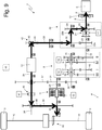
- Figure 9 illustrates a first launching mode which by using the torque developed by the electrical machine 12 which is caused to operate as an engine, simultaneously starts the internal combustion engine 5 and the movement of car 1; in this first launching mode, the locking device 40 locks the gear wheel 38 to the auxiliary shaft 34, clutch 11 is open, the locking devices 18 are in the idle position, the locking device 21 locks the gear wheel 23 to the drive shaft 8 (alternatively, the locking device 21 could lock the drive shaft 8 to shaft 22a), and the idle wheel 43 meshes (that is transmits the motion).
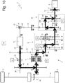
- Figure 10 illustrates a second launching mode which by using the torque developed by the electrical machine 12 which is caused to operate as an engine, simultaneously starts the internal combustion engine 5 and the movement of car 1; in this second launching mode, the locking device 40 locks the gear wheel 38 to the auxiliary shaft 34, clutch 11 is closed, the locking device 18 engages (for example) pair I of gears of gearbox 9 (obviously another pair of gears could be used), the locking device 21 locks the gear wheel 23 to the drive shaft 8 (alternatively, the locking device 21 could lock the drive shaft 8 to shaft 22a), and the freewheel 43 does not mesh (that is does not transmit the motion).
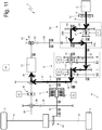
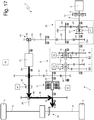
- Figure 11 illustrates a mode for recharging the system for storing electric energy when car 1 is stopped, by using the torque developed by the internal combustion engine 5 and causing the electrical machine 12 to operate as a generator; in this recharging mode, the locking device 40 locks the gear wheel 37 to the auxiliary shaft 34, clutch 11 is open, the locking device 18 engages (for example) pair I of gears of gearbox 9 (obviously another pair of gears could be used), the locking device 21 locks the gear wheel 23 to the drive shaft 8 (alternatively, the locking device 21 could lock the drive shaft 8 to shaft 22a), and the freewheel 43 does not mesh (that is does not transmit the motion).
- the locking device 40 locks the gear wheel 37 to the auxiliary shaft 34
- clutch 11 is open
- the locking device 18 engages (for example) pair I of gears of gearbox 9 (obviously another pair of gears could be used)
- the locking device 21 locks the gear wheel 23 to the drive shaft 8 (alternatively, the locking device 21 could lock the drive shaft 8
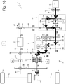
- Figure 12 illustrates a first mode for recharging the system for storing electric energy when car 1 is moving, by using the torque developed by the internal combustion engine 5 and causing the electrical machine 12 to operate as a generator; in this first recharging mode, the locking device 40 locks the gear wheel 38 to the auxiliary shaft 34, clutch 11 is closed, the locking device 18 engages (for example) pair I of gears of gearbox 9 (obviously another pair of gears could be used), the locking device 21 locks the gear wheel 23 to the drive shaft 8 (alternatively, the locking device 21 could lock the drive shaft 8 to shaft 22a), and the freewheel 43 does not mesh (that is does not transmit the motion).
- the locking device 40 locks the gear wheel 38 to the auxiliary shaft 34
- clutch 11 is closed
- the locking device 18 engages (for example) pair I of gears of gearbox 9 (obviously another pair of gears could be used)
- the locking device 21 locks the gear wheel 23 to the drive shaft 8 (alternatively, the locking device 21 could lock the drive
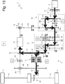
- Figure 13 illustrates a second mode for recharging the system for storing electric energy when car 1 is moving, by using the torque developed by the internal combustion engine 5 and causing the electrical machine 12 to operate as a generator; in this second recharging mode, the locking device 40 locks the gear wheel 37 to the auxiliary shaft 34, clutch 11 is closed, the locking device 18 engages (for example) pair I of gears of gearbox 9 (obviously another pair of gears could be used), the locking device 21 locks the gear wheel 23 to the drive shaft 8 (alternatively, the locking device 21 could lock the drive shaft 8 to shaft 22a), and the freewheel 43 does not mesh (that is does not transmit the motion).
- the locking device 40 locks the gear wheel 37 to the auxiliary shaft 34
- clutch 11 is closed
- the locking device 18 engages (for example) pair I of gears of gearbox 9 (obviously another pair of gears could be used)
- the locking device 21 locks the gear wheel 23 to the drive shaft 8 (alternatively, the locking device 21 could lock the drive
- Figure 14 illustrates a first combined-motion mode in which the torque applied to the rear driving wheels 3 originates in part from the internal combustion engine 5 and in part from the electrical machine 12 which operates as an engine; in this first combined-motion mode, the locking device 40 locks the gear wheel 38 to the auxiliary shaft 34, clutch 11 is closed, the locking device 18 engages (for example) pair I of gears of gearbox 9 (obviously another pair of gears could be used), the locking device 21 locks the gear wheel 23 to the drive shaft 8 (alternatively, the locking device 21 could lock the drive shaft 8 to shaft 22a), and the freewheel 43 does not mesh (that is does not transmit the motion).
- the locking device 40 locks the gear wheel 38 to the auxiliary shaft 34
- clutch 11 is closed
- the locking device 18 engages (for example) pair I of gears of gearbox 9 (obviously another pair of gears could be used)
- the locking device 21 locks the gear wheel 23 to the drive shaft 8 (alternatively, the locking device 21 could lock the drive shaft 8 to shaft 22a
- Figure 15 illustrates a second combined-motion mode in which the torque applied to the rear driving wheels 3 originates in part from the internal combustion engine 5 and in part from the electrical machine 12 which operates as an engine; in this second combined-motion mode, the locking device 40 locks the gear wheel 37 to the auxiliary shaft 34, clutch 11 is closed, the locking device 18 engages (for example) pair I of gears of gearbox 9 (obviously another pair of gears could be used), the locking device 21 locks the gear wheel 23 to the drive shaft 8 (alternatively, the locking device 21 could lock the drive shaft 8 to shaft 22a), and the freewheel 43 does not mesh (that is does not transmit the motion).
- the locking device 40 locks the gear wheel 37 to the auxiliary shaft 34
- clutch 11 is closed
- the locking device 18 engages (for example) pair I of gears of gearbox 9 (obviously another pair of gears could be used)
- the locking device 21 locks the gear wheel 23 to the drive shaft 8 (alternatively, the locking device 21 could lock the drive shaft 8 to shaft 22a
- Figure 16 illustrates a mode of purely thermal motion in which the torque applied to the rear driving wheels 3 originates exclusively from the internal combustion engine 5 and the electrical machine 12 is switched off (disabled); in this mode of purely thermal motion, the locking device 40 is in idle position, clutch 11 is closed, the locking device 18 engages (for example) pair I of gears of gearbox 9 (obviously another pair of gears could be used), the locking device 21 locks the gear wheel 23 to the drive shaft 8 (alternatively, the locking device 21 could lock the drive shaft 8 to shaft 22a), and the freewheel 43 does not mesh (that is does not transmit the motion).
- Figure 17 illustrates a first mode of purely electrical motion in which the torque applied to the rear driving wheels 3 originates exclusively from the electrical machine 12 which operates as an engine and the internal combustion engine 5 is switched off (disabled); in this first mode of purely electrical motion, the locking device 40 locks the gear wheel 38 to the auxiliary shaft 34, clutch 11 is open, the locking devices 18 and 21 are in the idle position, and the freewheel 43 does not mesh (that is does not transmit the motion).
- Figure 18 illustrates a second mode of purely electrical motion in which the torque applied to the rear driving wheels 3 originates exclusively from the electrical machine 12 which operates as an engine and the internal combustion engine 5 is switched off (disabled); in this second mode of purely electrical motion, the locking device 40 locks the gear wheel 37 to the auxiliary shaft 34, clutch 11 is closed, the locking devices 18 and 21 are in the idle position, and the freewheel 43 does not mesh (that is does not transmit the motion).
- Figure 19 illustrates a third mode of purely electrical motion in which the torque applied to the rear driving wheels 3 originates exclusively from the electrical machine 12 which operates as an engine and the internal combustion engine 5 is switched off (disabled); in this third mode of purely electrical motion, the locking devices 21 and 40 are in idle position, clutch 11 is closed, the locking device 18 engages (for example) pair I of gears of gearbox 9 (obviously another pair of gears could be used), and the freewheel 43 meshes (that is transmits the motion).
- Figure 20 illustrates a first mode of regenerative braking in which the electrical machine 12 is caused to operate as a generator for receiving, from the rear driving wheels 3, a braking torque which slows down car 1; in this first mode of regenerative braking, the locking device 40 locks the gear wheel 38 to the auxiliary shaft 34, clutch 11 is open, the locking devices 18 and 21 are in the idle position, and the freewheel 43 does not mesh (that is does not transmit the motion).
- Figure 21 illustrates a second mode of regenerative braking in which the electrical machine 12 is caused to operate as a generator for receiving, from the rear driving wheels 3, a braking torque which slows down car 1; in this second mode of regenerative braking, the locking device 40 locks the gear wheel 37 to the auxiliary shaft 34, clutch 11 is closed, the locking devices 18 and 21 are in the idle position, and the freewheel 43 does not mesh (that is does not transmit the motion).
- the electrical machine 12 is caused to operate as an engine to carry out the reverse movement of car 1 (the direction of rotation of the electrical machine 12 is easily reversible) and therefore reverse gear is not provided in gearbox 9. Moreover, according to a preferred embodiment, the electrical machine 12 is caused to operate as an engine to compensate for the "torque gap" to the rear driving wheels 3 when clutch 11 is opened to vary the gear ratio of gearbox 9 and/or of the drive device 20.
- clutch 11 is arranged in an unconventional position (i.e. downstream of the secondary shaft 15 of gearbox 9 between gearbox 9 and the differential gear 28) in which it poses no type of geometrical restraint on crankshaft 6 and on flywheel 13; thereby, it is possible to reduce the vertical volumes at flywheel 13 and therefore it is possible to lower the entire internal combustion engine 5 by hence lowering the centre of the road vehicle 1.
- gearbox 9 there is no drive device 20, and hence the gears are determined exclusively by gearbox 9.
- the automatic manual transmission 7 described above has several advantages as it allows an increased number of gears to be obtained within contained size, weight and costs and, at the same time, allows the electrical machine 12 to be mechanically connected to cause car 1 to be hybrid so that the electrical machine 12 effectively and energetically carries out various functions.
- the drive device 20 with variable gear ratio acts as a multiplier and allows the number of gears to be multiplied while at the same time containing the number of pairs of gears 16 and 17 and of locking devices 18 of gearbox 9.
- the two-ratio drive device 20 globally allows an eight-gear automatic manual transmission 7 to be obtained with only four pairs of gears 16 and 17 and two devices 18 for engaging gearbox 9; the drive device 20 comprises two pairs of gears and the locking device 21 and therefore globally the eight-gear automatic manual transmission 7 comprises fives pairs of gears and three locking devices 18 and 21.
- a similar conventional eight-gear automatic manual transmission would consist of eight pairs of gears and four locking devices; it is therefore apparent that two pairs of gears (from eight to six) and one locking device (from four to three) are saved in the above-described automatic manual transmission 7.
Landscapes
- Engineering & Computer Science (AREA)
- Transportation (AREA)
- Mechanical Engineering (AREA)
- Chemical & Material Sciences (AREA)
- Combustion & Propulsion (AREA)
- Automation & Control Theory (AREA)
- Structure Of Transmissions (AREA)
- Hybrid Electric Vehicles (AREA)
- Electric Propulsion And Braking For Vehicles (AREA)
Claims (15)
- Transmission manuelle automatique (7) pour une voiture hybride (1) munie d'un moteur à combustion interne (5) et d'une machine électrique (12) ; la transmission manuelle automatique (7) comprenant :une boîte de vitesses mécanique (9) à embrayage unique, qui est munie : d'un seul arbre primaire (14), qui est adapté pour recevoir un couple à partir d'un vilebrequin (6) du moteur à combustion interne (5), un seul arbre secondaire (15), qui est adapté pour transmettre le couple aux roues motrices (3), une pluralité de paires (I, II, III, IV) d'engrenages (16, 17), dont chacune a un rapport de vitesse correspondant et comprend un engrenage primaire (16), qui est monté sur l'arbre primaire (16), et un engrenage secondaire (17), qui est monté sur l'arbre secondaire (15) et s'engrène, de manière permanente, avec l'engrenage primaire (16), et une pluralité de premiers dispositifs de verrouillage assistés (18), dont chacun est monté sur un arbre (14 ; 15) et est adapté pour être actionné de manière à verrouiller au moins un engrenage correspondant (16 ; 17) sur l'arbre (14 ; 15) ;une pluralité de premiers actionneurs (19), dont chacun est couplé à un premier dispositif de verrouillage (18) correspondant, de manière à actionner le dispositif de verrouillage (18) ;un engrenage différentiel (28), qui reçoit le mouvement de l'arbre secondaire (15) de la boîte de vitesses (9) et transmet le mouvement aux roues motrices (3) ;un seul embrayage (11), qui est interposé entre le seul arbre secondaire (15) de la boîte de vitesses (9) et l'engrenage différentiel (28) ;un deuxième actionneur (33), qui est couplé à l'embrayage (11), de manière à désembrayer et embrayer l'embrayage (11) ;la transmission manuelle automatique (7) étant caractérisée en ce qu'elle comprend :un arbre auxiliaire (34), qui est différent et séparé de l'arbre primaire (14) et de l'arbre secondaire (15) et le long duquel la machine électrique (12) est montée ;un premier train d'engrenages, qui est différent et séparé des paires (I, II, III, IV) d'engrenages (16, 17) de la boîte de vitesses (9) et relie une première extrémité de l'arbre auxiliaire (34), qui est agencé en amont de la machine électrique (12), à l'arbre primaire (14) de la boîte de vitesses (9) ; etun deuxième train d'engrenages, qui est différent et séparé des paires (I, II, III, IV) d'engrenages (16, 17) de la boîte de vitesses (9) et relie une deuxième extrémité de l'arbre auxiliaire (34), qui est agencé en aval de la machine électrique (12), à un arbre de sortie (32) de l'embrayage (11).
- Transmission manuelle automatique (7) selon la revendication 1, et comprenant :un troisième train d'engrenages, qui relie la deuxième extrémité de l'arbre auxiliaire (34), qui est agencé en aval de la machine électrique (12), à un arbre d'entrée (29) de l'embrayage (11) ;un deuxième dispositif de verrouillage (40), qui est adapté pour verrouiller alternativement le deuxième train d'engrenages ou le troisième train d'engrenages sur l'arbre auxiliaire (34) ; etun troisième actionneur (41), qui est couplé au deuxième dispositif de verrouillage (40), de manière à actionner le deuxième dispositif de verrouillage (40).
- Transmission manuelle automatique (7) selon la revendication 1 ou 2 et comprenant un dispositif de désaccouplement (42), qui est adapté à séparer l'arbre auxiliaire (34) de l'arbre primaire (14) de la boîte de vitesses (9).
- Transmission manuelle automatique (7) selon la revendication 3, dans laquelle le dispositif de désaccouplement (42) est passif et comprend une roue libre (43), qui transmet le mouvement lorsqu'elle tourne dans une certaine direction et ne transmet pas le mouvement lorsqu'elle tourne dans la direction opposée.
- Transmission manuelle automatique (7) selon la revendication 4, dans laquelle la roue libre (43) présente un désaccouplement centrifuge, qui permet de ne transmettre le mouvement que lorsque la vitesse de rotation est inférieure à une vitesse de rotation maximale prédéterminée.
- Transmission manuelle automatique (7) selon la revendication 3, dans laquelle le dispositif de désaccouplement (42) est actif et comprend un embrayage assisté (44) et un quatrième actionneur (45), qui agit sur l'embrayage (44) de manière à désembrayer et embrayer l'embrayage (44).
- Transmission manuelle automatique (7) selon l'une des revendications 1 à 6, dans laquelle :le deuxième train d'engrenages comprend une première roue dentée (37), qui est montée folle sur l'arbre auxiliaire (34), et une deuxième roue dentée (31) qui est couplée par cannelure à l'arbre d'entrée (29) de l'embrayage (11) et s'engrène avec la première roue dentée (37) ; etune troisième roue dentée (30) est prévue, qui s'engrène avec la deuxième roue dentée (31) et est solidaire de l'arbre secondaire (15) de la boîte de vitesses (9), de manière à amener l'arbre d'entrée (29) de l'embrayage (11) à être angulairement solidaire de l'arbre secondaire (15) de la boîte de vitesses (9).
- Transmission manuelle automatique (7) selon l'une des revendications 1 à 7, et comprenant :un dispositif d'entraînement assisté (20) ayant un rapport de vitesse variable, qui est interposé entre un arbre d'entraînement (8), qui est adapté pour recevoir le couple à partir du vilebrequin (6) du moteur à combustion interne (5), et l'arbre primaire (14) de la boîte de vitesses (9) et peut être réglé de manière à présenter deux rapports de vitesses différents : un premier rapport de vitesse à entraînement direct uniforme et un deuxième rapport de vitesse augmenté ; etun cinquième actionneur (27), qui est couplé au dispositif d'entraînement (20), de manière à faire varier le rapport de vitesse du dispositif d'entraînement (20).
- Transmission manuelle automatique (7) selon la revendication 8, dans laquelle le premier train d'engrenages est ajusté sur le dispositif d'entraînement (20).
- Transmission manuelle automatique (7) selon la revendication 8 ou 9, dans laquelle le dispositif d'entraînement (20) comprend :un premier arbre (22a), qui est angulairement solidaire de l'arbre primaire (14) de la boîte de vitesses (9), fait face à l'arbre d'entraînement (8) et est coaxial à celui-ci ;un deuxième arbre (22b), qui est parallèle au premier arbre (22a) ;une quatrième roue dentée (23), qui est montée folle autour de l'arbre d'entraînement (8) ;une cinquième roue dentée (24), qui est solidaire du deuxième arbre (22b) et s'engrène avec la quatrième roue dentée (23) ;une sixième roue dentée (25), qui est solidaire du premier arbre (22a) ;une septième roue dentée (26), qui est solidaire du deuxième arbre (22b) et s'engrène avec la sixième roue dentée (25) ; etun dispositif de verrouillage (21), qui est adapté pour être actionné par le cinquième actionneur (27) de manière à verrouiller alternativement la quatrième roue dentée (23) sur l'arbre d'entraînement (8) ou le premier arbre (22a) sur l'arbre d'entraînement (8).
- Transmission manuelle automatique (7) selon la revendication 10, dans laquelle le premier train d'engrenages comprend :une huitième roue dentée (36), qui s'engrène avec la septième roue dentée (26) ; etune neuvième roue dentée (35), qui s'engrène avec la huitième roue dentée (36) et est reliée mécaniquement à l'arbre auxiliaire (34).
- Transmission manuelle automatique (7) selon l'une des revendications 8 à 11, dans laquelle le deuxième rapport de vitesse augmenté du dispositif d'entraînement (21) et les rapports de vitesses des paires (I, II, III, IV) d'engrenages (16, 17) de la boîte de vitesses (9) présentent des valeurs de sorte que toutes les vitesses qui peuvent être obtenues en combinant un rapport de vitesse quelconque du dispositif d'entraînement (21) avec un rapport de vitesse quelconque de la boîte de vitesses (9) présentent des rapports de vitesse sans chevauchement.
- Transmission manuelle automatique (7) selon l'une des revendications 8 à 12, dans laquelle, afin d'effectuer, en séquence, tous les passages à une vitesse supérieure allant de la vitesse la plus faible vers la vitesse la plus élevée, une unité de commande (46) active, à chaque changement de vitesse, le cinquième actionneur (27), de manière à faire varier le rapport de vitesse du dispositif d'entraînement (21), et active d'une manière alternée, c'est-à-dire n'active pas à un changement de vitesse et active au changement de vitesse suivant, au moins un premier actionneur (19) d'un dispositif de verrouillage (18), de manière à changer la paire (I, II, III, IV) d'engrenages (16, 17) qui est engagée dans la boîte de vitesses (9).
- Transmission manuelle automatique (7) selon l'une des revendications 8 à 12, dans laquelle, afin d'effectuer, en séquence, tous les passages à une vitesse supérieure allant de la vitesse la plus faible vers la vitesse la plus élevée, une unité de commande (46) active, à chaque changement de vitesse, au moins un premier actionneur (19) d'un dispositif de verrouillage (18), de manière à changer la paire (I, II, III, IV) d'engrenages (16, 17) qui est engagée dans la boîte de vitesses (9), et active d'une manière alternée, c'est-à-dire n'active pas à un changement de vitesse et active au changement de vitesse suivant, le cinquième actionneur (27), de manière à faire varier le rapport de vitesse du dispositif d'entraînement (21).
- Transmission manuelle automatique (7) selon l'une des revendications 8 à 12, dans laquelle :toutes les vitesses sont divisées en un groupe inférieur et un groupe supérieur, de sorte que la vitesse la plus élevée du groupe inférieur présente un rapport de vitesse plus faible par rapport à la vitesse la plus faible du groupe supérieur ;afin d'effectuer un changement de vitesse dans un même groupe, l'unité de commande (46) active exclusivement au moins un premier actionneur (19) d'un dispositif de verrouillage (18), de manière à changer la paire (I, II, III, IV) d'engrenages (16, 17) qui est engagée dans la boîte de vitesses (9) ; etafin d'effectuer un changement de vitesse entre une vitesse du groupe inférieur et une vitesse du groupe supérieur, l'unité de commande (46) active simultanément au moins un premier actionneur (19) d'un dispositif de verrouillage (18) de manière à changer la paire (I, II, III, IV) d'engrenages (16, 17) qui est engagée dans la boîte de vitesses (9), et le cinquième actionneur (27), de manière à faire varier le rapport de vitesse du dispositif d'entraînement (21).
Applications Claiming Priority (1)
| Application Number | Priority Date | Filing Date | Title |
|---|---|---|---|
| IT000363A ITBO20120363A1 (it) | 2012-07-03 | 2012-07-03 | Trasmissione manuale automatica per una vettura ibrida provvista di un motore a combustione interna e di una macchina elettrica |
Publications (2)
| Publication Number | Publication Date |
|---|---|
| EP2682293A1 EP2682293A1 (fr) | 2014-01-08 |
| EP2682293B1 true EP2682293B1 (fr) | 2018-04-04 |
Family
ID=46758818
Family Applications (1)
| Application Number | Title | Priority Date | Filing Date |
|---|---|---|---|
| EP13174989.7A Active EP2682293B1 (fr) | 2012-07-03 | 2013-07-03 | Boite de vitesses robotisée avec moteur à explosion et machine électrique |
Country Status (4)
| Country | Link |
|---|---|
| US (1) | US8939867B2 (fr) |
| EP (1) | EP2682293B1 (fr) |
| JP (1) | JP6292780B2 (fr) |
| IT (1) | ITBO20120363A1 (fr) |
Families Citing this family (23)
| Publication number | Priority date | Publication date | Assignee | Title |
|---|---|---|---|---|
| ITBO20120316A1 (it) * | 2012-06-07 | 2013-12-08 | Ferrari Spa | Trasmissione manuale automatica per una vettura provvista di un motore a combustione interna |
| ES2660552T3 (es) | 2012-09-06 | 2018-03-22 | Iveco S.P.A. | Vehículo que comprende un distribuidor de torque para dos ejes, método para controlar el mismo, programa informático y medios que pueden ser leídos por una computadora |
| EP3109111B1 (fr) * | 2014-02-20 | 2019-08-28 | Panasonic Intellectual Property Management Co., Ltd. | Système hybride de véhicule |
| DE102014111649A1 (de) * | 2014-08-14 | 2016-02-18 | Thyssenkrupp Ag | Unterwasserfahrzeug, Verfahren zum Aufnehmen einer Last vom Meeresgrund und ein Verfahren zum Absetzen einer Last am Meeresgrund |
| CN105644335B (zh) | 2014-11-14 | 2020-02-28 | 上海汽车集团股份有限公司 | 车辆用双电机动力系统和双电机混合动力系统 |
| CN106143102B (zh) | 2014-11-18 | 2019-07-16 | 上海汽车集团股份有限公司 | 车辆混合动力驱动系统及其变速器 |
| CN105673780B (zh) | 2014-11-18 | 2019-08-06 | 上海汽车集团股份有限公司 | 车辆混合动力驱动系统及其变速器 |
| CN105620460B (zh) | 2014-11-18 | 2019-07-16 | 上海汽车集团股份有限公司 | 用于混合动力车辆变速器的控制系统和方法 |
| CN105667491B (zh) | 2014-11-18 | 2019-07-16 | 上海汽车集团股份有限公司 | 用于混合动力车辆变速器的控制系统和方法 |
| CN106274460B (zh) | 2015-05-29 | 2019-12-10 | 上海汽车集团股份有限公司 | 双电机电动车辆的电驱变速箱控制装置和方法 |
| CN106274464B (zh) | 2015-05-29 | 2019-09-10 | 上海汽车集团股份有限公司 | 纯电动车辆的双电机动力系统和控制方法 |
| EP3100891B1 (fr) | 2015-06-04 | 2017-11-08 | FERRARI S.p.A. | Transmission manuelle automatique pour une voiture hybride pourvue d'un moteur à combustion interne et d'une machine électrique |
| IL242226B2 (en) | 2015-10-22 | 2023-03-01 | Peleg Amitai | System and method for launch and recovery of a marine vessel |
| ITUB20160890A1 (it) * | 2016-02-19 | 2017-08-19 | Iveco Spa | Trasmissione di un veicolo ibrido, in particolare di un veicolo industriale o commerciale |
| ITUB20160874A1 (it) * | 2016-02-19 | 2017-08-19 | Iveco Spa | Trasmissione di un veicolo ibrido, in particolare di un veicolo industriale o commerciale |
| US10259308B2 (en) * | 2016-02-29 | 2019-04-16 | Ford Global Technologies, Llc | Axle assembly for hybrid electric vehicle |
| ITUA20164676A1 (it) * | 2016-06-27 | 2017-12-27 | Magneti Marelli Spa | Apparato di trasmissione per veicoli muniti di cambio manuale robotizzato, gruppo motopropulsore e relativo veicolo comprendente detto apparato |
| DE102016213156A1 (de) * | 2016-07-19 | 2018-01-25 | Schaeffler Technologies AG & Co. KG | Antriebsstrang für ein Hybridfahrzeug ausgelegt zum automatisierten Vorwärts- und Rückwärtsfahren |
| CN109835166A (zh) * | 2017-11-29 | 2019-06-04 | 上汽通用汽车有限公司 | 混合动力传动系统和车辆 |
| CN109835169A (zh) * | 2017-11-29 | 2019-06-04 | 上汽通用汽车有限公司 | 混合动力传动系统和车辆 |
| JP6784930B1 (ja) * | 2019-05-16 | 2020-11-18 | 株式会社椿本チエイン | 動力伝達機構 |
| GB2605833A (en) * | 2021-04-15 | 2022-10-19 | Contract Innovation Ltd | Drivetrain |
| JP2026005611A (ja) * | 2024-06-27 | 2026-01-16 | トヨタ自動車株式会社 | ハイブリッド車両 |
Family Cites Families (27)
| Publication number | Priority date | Publication date | Assignee | Title |
|---|---|---|---|---|
| JPS5821284Y2 (ja) * | 1977-02-19 | 1983-05-06 | マツダ株式会社 | ハイブリツドカ−のモ−タ制御装置 |
| JPS61286644A (ja) * | 1985-06-11 | 1986-12-17 | Mazda Motor Corp | 歯車式変速装置 |
| JP3595627B2 (ja) * | 1996-05-27 | 2004-12-02 | タイ−ハー ヤン | 多機能複合動力装置 |
| JP2001004007A (ja) * | 1999-06-17 | 2001-01-09 | Exedy Corp | 車両用多段変速機 |
| DE10165097B3 (de) * | 2000-07-18 | 2015-07-23 | Schaeffler Technologies AG & Co. KG | Doppelkupplungsgetriebe |
| JP3952005B2 (ja) * | 2003-11-18 | 2007-08-01 | 日産自動車株式会社 | ハイブリッド車両の駆動装置 |
| JP4226610B2 (ja) * | 2006-03-28 | 2009-02-18 | 本田技研工業株式会社 | ハイブリッド車両 |
| JP2008101586A (ja) * | 2006-10-20 | 2008-05-01 | Mitsubishi Electric Corp | 車両用電動発電装置 |
| US7846051B2 (en) * | 2007-05-11 | 2010-12-07 | Gm Global Technology Operations, Inc. | Hybrid powertrain with an engine input clutch and method of control |
| JP2009035212A (ja) * | 2007-08-03 | 2009-02-19 | Nissan Motor Co Ltd | 車両用駆動装置 |
| WO2009103267A2 (fr) * | 2008-02-20 | 2009-08-27 | Luk Lamellen Und Kupplungsbau Beteiligungs Kg | Volant comprenant une couronne dentée de démarreur |
| JP4506881B2 (ja) * | 2008-06-19 | 2010-07-21 | 株式会社デンソー | ハイブリッド車両の制御装置 |
| DE102008031456B4 (de) * | 2008-07-05 | 2021-05-27 | EGS Entwicklungsgesellschaft für Getriebesysteme mbH | Lastschaltgetriebe |
| JP5160367B2 (ja) * | 2008-10-10 | 2013-03-13 | 三菱農機株式会社 | 作業車両 |
| JP5379554B2 (ja) * | 2009-04-30 | 2013-12-25 | アイシン・エーアイ株式会社 | 車両の動力伝達制御装置 |
| DE112010002695T5 (de) * | 2009-06-24 | 2012-08-30 | Fisker Automotive, Inc. | Antriebskonfigurationen für hochhybride reihen-/parallel-motor-antriebssyteme mit hoher drehzahl |
| ITBO20090465A1 (it) * | 2009-07-21 | 2011-01-22 | Ferrari Spa | Trasmissione per un veicolo stradale con propulsione ibrida |
| ITBO20090573A1 (it) * | 2009-09-09 | 2011-03-10 | Ferrari Spa | Veicolo ibrido |
| JP2011110943A (ja) * | 2009-11-24 | 2011-06-09 | Denso Corp | 車両駆動システムの制御装置 |
| US8241173B2 (en) * | 2010-01-12 | 2012-08-14 | GM Global Technology Operations LLC | Single motor hybrid transmission |
| JP5392398B2 (ja) * | 2010-03-10 | 2014-01-22 | トヨタ自動車株式会社 | 車両用ハイブリッド駆動装置 |
| JP5417225B2 (ja) * | 2010-03-12 | 2014-02-12 | 富士重工業株式会社 | ハイブリッド駆動装置 |
| JP5648428B2 (ja) * | 2010-11-02 | 2015-01-07 | アイシン精機株式会社 | ハイブリッド車両の変速装置 |
| EP2468553A1 (fr) * | 2010-12-21 | 2012-06-27 | Saab Automobile AB | Agencement de transmission de véhicule |
| DE102011088395A1 (de) * | 2010-12-21 | 2012-06-21 | Robert Bosch Gmbh | Parallelhybridantriebsstrang |
| JP5408506B2 (ja) * | 2011-04-20 | 2014-02-05 | アイシン・エィ・ダブリュ株式会社 | 車両用駆動装置 |
| ITBO20120316A1 (it) * | 2012-06-07 | 2013-12-08 | Ferrari Spa | Trasmissione manuale automatica per una vettura provvista di un motore a combustione interna |
-
2012
- 2012-07-03 IT IT000363A patent/ITBO20120363A1/it unknown
-
2013
- 2013-07-02 US US13/933,792 patent/US8939867B2/en active Active
- 2013-07-03 JP JP2013139592A patent/JP6292780B2/ja active Active
- 2013-07-03 EP EP13174989.7A patent/EP2682293B1/fr active Active
Non-Patent Citations (1)
| Title |
|---|
| None * |
Also Published As
| Publication number | Publication date |
|---|---|
| ITBO20120363A1 (it) | 2014-01-04 |
| EP2682293A1 (fr) | 2014-01-08 |
| US20140011631A1 (en) | 2014-01-09 |
| JP6292780B2 (ja) | 2018-03-14 |
| US8939867B2 (en) | 2015-01-27 |
| JP2014065480A (ja) | 2014-04-17 |
Similar Documents
| Publication | Publication Date | Title |
|---|---|---|
| EP2682293B1 (fr) | Boite de vitesses robotisée avec moteur à explosion et machine électrique | |
| JP4942212B2 (ja) | ハイブリッド動力装置 | |
| EP2345829B1 (fr) | Boite de vitesse | |
| US7082850B2 (en) | Hybrid powertrain system | |
| JP6517865B2 (ja) | 自動車両用ハイブリッド伝動装置 | |
| US10814714B2 (en) | Hybrid powertrain for a hybrid-drive motor vehicle | |
| US8241173B2 (en) | Single motor hybrid transmission | |
| JP5467197B2 (ja) | ハイブリッド駆動装置 | |
| EP2530356B1 (fr) | Système de commande de véhicule | |
| CN102271948A (zh) | 混合动力车的动力传递装置 | |
| JP6063128B2 (ja) | ハイブリッド車両の駆動装置 | |
| JP5395115B2 (ja) | ハイブリッド駆動装置 | |
| JP5997452B2 (ja) | ハイブリッド車両の駆動装置 | |
| EP3100891B1 (fr) | Transmission manuelle automatique pour une voiture hybride pourvue d'un moteur à combustion interne et d'une machine électrique | |
| CN209240861U (zh) | 动力驱动系统和车辆 | |
| CN107709070A (zh) | 用于混合动力机动车的驱动装置和具有该驱动装置的机动车 | |
| US20180281580A1 (en) | Transmission Assembly for a Hybrid Vehicle | |
| CN209240860U (zh) | 动力驱动系统和车辆 | |
| CN114571982A (zh) | 混合动力变速器、混合动力变速系统和车辆 | |
| JP2022073265A (ja) | 車両用駆動装置 |
Legal Events
| Date | Code | Title | Description |
|---|---|---|---|
| PUAI | Public reference made under article 153(3) epc to a published international application that has entered the european phase |
Free format text: ORIGINAL CODE: 0009012 |
|
| 17P | Request for examination filed |
Effective date: 20131010 |
|
| AK | Designated contracting states |
Kind code of ref document: A1 Designated state(s): AL AT BE BG CH CY CZ DE DK EE ES FI FR GB GR HR HU IE IS IT LI LT LU LV MC MK MT NL NO PL PT RO RS SE SI SK SM TR |
|
| AX | Request for extension of the european patent |
Extension state: BA ME |
|
| 17Q | First examination report despatched |
Effective date: 20170217 |
|
| REG | Reference to a national code |
Ref country code: DE Ref legal event code: R079 Ref document number: 602013035306 Country of ref document: DE Free format text: PREVIOUS MAIN CLASS: B60K0006480000 Ipc: B60K0006383000 |
|
| GRAP | Despatch of communication of intention to grant a patent |
Free format text: ORIGINAL CODE: EPIDOSNIGR1 |
|
| RIC1 | Information provided on ipc code assigned before grant |
Ipc: B60K 6/48 20071001ALI20170928BHEP Ipc: F16H 37/04 20060101ALI20170928BHEP Ipc: B60W 20/30 20160101ALI20170928BHEP Ipc: B60K 6/387 20071001ALI20170928BHEP Ipc: B60K 6/54 20071001ALI20170928BHEP Ipc: B60K 6/383 20071001AFI20170928BHEP |
|
| INTG | Intention to grant announced |
Effective date: 20171025 |
|
| GRAS | Grant fee paid |
Free format text: ORIGINAL CODE: EPIDOSNIGR3 |
|
| GRAA | (expected) grant |
Free format text: ORIGINAL CODE: 0009210 |
|
| AK | Designated contracting states |
Kind code of ref document: B1 Designated state(s): AL AT BE BG CH CY CZ DE DK EE ES FI FR GB GR HR HU IE IS IT LI LT LU LV MC MK MT NL NO PL PT RO RS SE SI SK SM TR |
|
| REG | Reference to a national code |
Ref country code: GB Ref legal event code: FG4D |
|
| REG | Reference to a national code |
Ref country code: CH Ref legal event code: EP |
|
| REG | Reference to a national code |
Ref country code: AT Ref legal event code: REF Ref document number: 985215 Country of ref document: AT Kind code of ref document: T Effective date: 20180415 |
|
| REG | Reference to a national code |
Ref country code: IE Ref legal event code: FG4D |
|
| REG | Reference to a national code |
Ref country code: DE Ref legal event code: R096 Ref document number: 602013035306 Country of ref document: DE |
|
| REG | Reference to a national code |
Ref country code: NL Ref legal event code: MP Effective date: 20180404 |
|
| REG | Reference to a national code |
Ref country code: LT Ref legal event code: MG4D |
|
| PG25 | Lapsed in a contracting state [announced via postgrant information from national office to epo] |
Ref country code: NL Free format text: LAPSE BECAUSE OF FAILURE TO SUBMIT A TRANSLATION OF THE DESCRIPTION OR TO PAY THE FEE WITHIN THE PRESCRIBED TIME-LIMIT Effective date: 20180404 |
|
| PG25 | Lapsed in a contracting state [announced via postgrant information from national office to epo] |
Ref country code: SE Free format text: LAPSE BECAUSE OF FAILURE TO SUBMIT A TRANSLATION OF THE DESCRIPTION OR TO PAY THE FEE WITHIN THE PRESCRIBED TIME-LIMIT Effective date: 20180404 Ref country code: LT Free format text: LAPSE BECAUSE OF FAILURE TO SUBMIT A TRANSLATION OF THE DESCRIPTION OR TO PAY THE FEE WITHIN THE PRESCRIBED TIME-LIMIT Effective date: 20180404 Ref country code: ES Free format text: LAPSE BECAUSE OF FAILURE TO SUBMIT A TRANSLATION OF THE DESCRIPTION OR TO PAY THE FEE WITHIN THE PRESCRIBED TIME-LIMIT Effective date: 20180404 Ref country code: AL Free format text: LAPSE BECAUSE OF FAILURE TO SUBMIT A TRANSLATION OF THE DESCRIPTION OR TO PAY THE FEE WITHIN THE PRESCRIBED TIME-LIMIT Effective date: 20180404 Ref country code: NO Free format text: LAPSE BECAUSE OF FAILURE TO SUBMIT A TRANSLATION OF THE DESCRIPTION OR TO PAY THE FEE WITHIN THE PRESCRIBED TIME-LIMIT Effective date: 20180704 Ref country code: PL Free format text: LAPSE BECAUSE OF FAILURE TO SUBMIT A TRANSLATION OF THE DESCRIPTION OR TO PAY THE FEE WITHIN THE PRESCRIBED TIME-LIMIT Effective date: 20180404 Ref country code: FI Free format text: LAPSE BECAUSE OF FAILURE TO SUBMIT A TRANSLATION OF THE DESCRIPTION OR TO PAY THE FEE WITHIN THE PRESCRIBED TIME-LIMIT Effective date: 20180404 Ref country code: BG Free format text: LAPSE BECAUSE OF FAILURE TO SUBMIT A TRANSLATION OF THE DESCRIPTION OR TO PAY THE FEE WITHIN THE PRESCRIBED TIME-LIMIT Effective date: 20180704 |
|
| PG25 | Lapsed in a contracting state [announced via postgrant information from national office to epo] |
Ref country code: RS Free format text: LAPSE BECAUSE OF FAILURE TO SUBMIT A TRANSLATION OF THE DESCRIPTION OR TO PAY THE FEE WITHIN THE PRESCRIBED TIME-LIMIT Effective date: 20180404 Ref country code: HR Free format text: LAPSE BECAUSE OF FAILURE TO SUBMIT A TRANSLATION OF THE DESCRIPTION OR TO PAY THE FEE WITHIN THE PRESCRIBED TIME-LIMIT Effective date: 20180404 Ref country code: LV Free format text: LAPSE BECAUSE OF FAILURE TO SUBMIT A TRANSLATION OF THE DESCRIPTION OR TO PAY THE FEE WITHIN THE PRESCRIBED TIME-LIMIT Effective date: 20180404 Ref country code: GR Free format text: LAPSE BECAUSE OF FAILURE TO SUBMIT A TRANSLATION OF THE DESCRIPTION OR TO PAY THE FEE WITHIN THE PRESCRIBED TIME-LIMIT Effective date: 20180705 |
|
| REG | Reference to a national code |
Ref country code: AT Ref legal event code: MK05 Ref document number: 985215 Country of ref document: AT Kind code of ref document: T Effective date: 20180404 |
|
| PG25 | Lapsed in a contracting state [announced via postgrant information from national office to epo] |
Ref country code: PT Free format text: LAPSE BECAUSE OF FAILURE TO SUBMIT A TRANSLATION OF THE DESCRIPTION OR TO PAY THE FEE WITHIN THE PRESCRIBED TIME-LIMIT Effective date: 20180806 |
|
| REG | Reference to a national code |
Ref country code: DE Ref legal event code: R097 Ref document number: 602013035306 Country of ref document: DE |
|
| PG25 | Lapsed in a contracting state [announced via postgrant information from national office to epo] |
Ref country code: DK Free format text: LAPSE BECAUSE OF FAILURE TO SUBMIT A TRANSLATION OF THE DESCRIPTION OR TO PAY THE FEE WITHIN THE PRESCRIBED TIME-LIMIT Effective date: 20180404 Ref country code: AT Free format text: LAPSE BECAUSE OF FAILURE TO SUBMIT A TRANSLATION OF THE DESCRIPTION OR TO PAY THE FEE WITHIN THE PRESCRIBED TIME-LIMIT Effective date: 20180404 Ref country code: EE Free format text: LAPSE BECAUSE OF FAILURE TO SUBMIT A TRANSLATION OF THE DESCRIPTION OR TO PAY THE FEE WITHIN THE PRESCRIBED TIME-LIMIT Effective date: 20180404 Ref country code: SK Free format text: LAPSE BECAUSE OF FAILURE TO SUBMIT A TRANSLATION OF THE DESCRIPTION OR TO PAY THE FEE WITHIN THE PRESCRIBED TIME-LIMIT Effective date: 20180404 Ref country code: CZ Free format text: LAPSE BECAUSE OF FAILURE TO SUBMIT A TRANSLATION OF THE DESCRIPTION OR TO PAY THE FEE WITHIN THE PRESCRIBED TIME-LIMIT Effective date: 20180404 Ref country code: RO Free format text: LAPSE BECAUSE OF FAILURE TO SUBMIT A TRANSLATION OF THE DESCRIPTION OR TO PAY THE FEE WITHIN THE PRESCRIBED TIME-LIMIT Effective date: 20180404 |
|
| REG | Reference to a national code |
Ref country code: CH Ref legal event code: PK Free format text: RETTIFICHE |
|
| PLBE | No opposition filed within time limit |
Free format text: ORIGINAL CODE: 0009261 |
|
| STAA | Information on the status of an ep patent application or granted ep patent |
Free format text: STATUS: NO OPPOSITION FILED WITHIN TIME LIMIT |
|
| RIC2 | Information provided on ipc code assigned after grant |
Ipc: B60K 6/383 20071001AFI20170928BHEP Ipc: B60W 20/30 20160101ALI20170928BHEP Ipc: B60K 6/48 20071001ALI20170928BHEP Ipc: F16H 37/04 20060101ALI20170928BHEP Ipc: B60K 6/54 20071001ALI20170928BHEP Ipc: B60K 6/387 20071001ALI20170928BHEP |
|
| PG25 | Lapsed in a contracting state [announced via postgrant information from national office to epo] |
Ref country code: SM Free format text: LAPSE BECAUSE OF FAILURE TO SUBMIT A TRANSLATION OF THE DESCRIPTION OR TO PAY THE FEE WITHIN THE PRESCRIBED TIME-LIMIT Effective date: 20180404 |
|
| REG | Reference to a national code |
Ref country code: CH Ref legal event code: PL |
|
| 26N | No opposition filed |
Effective date: 20190107 |
|
| PG25 | Lapsed in a contracting state [announced via postgrant information from national office to epo] |
Ref country code: LU Free format text: LAPSE BECAUSE OF NON-PAYMENT OF DUE FEES Effective date: 20180703 Ref country code: MC Free format text: LAPSE BECAUSE OF FAILURE TO SUBMIT A TRANSLATION OF THE DESCRIPTION OR TO PAY THE FEE WITHIN THE PRESCRIBED TIME-LIMIT Effective date: 20180404 |
|
| REG | Reference to a national code |
Ref country code: BE Ref legal event code: MM Effective date: 20180731 |
|
| REG | Reference to a national code |
Ref country code: IE Ref legal event code: MM4A |
|
| PG25 | Lapsed in a contracting state [announced via postgrant information from national office to epo] |
Ref country code: FR Free format text: LAPSE BECAUSE OF NON-PAYMENT OF DUE FEES Effective date: 20180731 Ref country code: CH Free format text: LAPSE BECAUSE OF NON-PAYMENT OF DUE FEES Effective date: 20180731 Ref country code: IE Free format text: LAPSE BECAUSE OF NON-PAYMENT OF DUE FEES Effective date: 20180703 Ref country code: LI Free format text: LAPSE BECAUSE OF NON-PAYMENT OF DUE FEES Effective date: 20180731 |
|
| PG25 | Lapsed in a contracting state [announced via postgrant information from national office to epo] |
Ref country code: BE Free format text: LAPSE BECAUSE OF NON-PAYMENT OF DUE FEES Effective date: 20180731 Ref country code: SI Free format text: LAPSE BECAUSE OF FAILURE TO SUBMIT A TRANSLATION OF THE DESCRIPTION OR TO PAY THE FEE WITHIN THE PRESCRIBED TIME-LIMIT Effective date: 20180404 |
|
| PG25 | Lapsed in a contracting state [announced via postgrant information from national office to epo] |
Ref country code: MT Free format text: LAPSE BECAUSE OF NON-PAYMENT OF DUE FEES Effective date: 20180703 |
|
| PG25 | Lapsed in a contracting state [announced via postgrant information from national office to epo] |
Ref country code: TR Free format text: LAPSE BECAUSE OF FAILURE TO SUBMIT A TRANSLATION OF THE DESCRIPTION OR TO PAY THE FEE WITHIN THE PRESCRIBED TIME-LIMIT Effective date: 20180404 |
|
| PG25 | Lapsed in a contracting state [announced via postgrant information from national office to epo] |
Ref country code: HU Free format text: LAPSE BECAUSE OF FAILURE TO SUBMIT A TRANSLATION OF THE DESCRIPTION OR TO PAY THE FEE WITHIN THE PRESCRIBED TIME-LIMIT; INVALID AB INITIO Effective date: 20130703 |
|
| PG25 | Lapsed in a contracting state [announced via postgrant information from national office to epo] |
Ref country code: CY Free format text: LAPSE BECAUSE OF FAILURE TO SUBMIT A TRANSLATION OF THE DESCRIPTION OR TO PAY THE FEE WITHIN THE PRESCRIBED TIME-LIMIT Effective date: 20180404 Ref country code: MK Free format text: LAPSE BECAUSE OF NON-PAYMENT OF DUE FEES Effective date: 20180404 |
|
| PG25 | Lapsed in a contracting state [announced via postgrant information from national office to epo] |
Ref country code: IS Free format text: LAPSE BECAUSE OF FAILURE TO SUBMIT A TRANSLATION OF THE DESCRIPTION OR TO PAY THE FEE WITHIN THE PRESCRIBED TIME-LIMIT Effective date: 20180804 |
|
| P01 | Opt-out of the competence of the unified patent court (upc) registered |
Effective date: 20230525 |
|
| PGFP | Annual fee paid to national office [announced via postgrant information from national office to epo] |
Ref country code: DE Payment date: 20250728 Year of fee payment: 13 |
|
| PGFP | Annual fee paid to national office [announced via postgrant information from national office to epo] |
Ref country code: IT Payment date: 20250630 Year of fee payment: 13 |
|
| PGFP | Annual fee paid to national office [announced via postgrant information from national office to epo] |
Ref country code: GB Payment date: 20250722 Year of fee payment: 13 |