EP2682327A2 - Elektrisches Servolenksystem - Google Patents
Elektrisches Servolenksystem Download PDFInfo
- Publication number
- EP2682327A2 EP2682327A2 EP13174095.3A EP13174095A EP2682327A2 EP 2682327 A2 EP2682327 A2 EP 2682327A2 EP 13174095 A EP13174095 A EP 13174095A EP 2682327 A2 EP2682327 A2 EP 2682327A2
- Authority
- EP
- European Patent Office
- Prior art keywords
- tooth surfaces
- teeth
- surface roughness
- gear
- worm wheel
- Prior art date
- Legal status (The legal status is an assumption and is not a legal conclusion. Google has not performed a legal analysis and makes no representation as to the accuracy of the status listed.)
- Withdrawn
Links
- 230000003746 surface roughness Effects 0.000 claims abstract description 47
- 239000011347 resin Substances 0.000 claims abstract description 20
- 229920005989 resin Polymers 0.000 claims abstract description 20
- 239000012783 reinforcing fiber Substances 0.000 claims abstract description 17
- 239000011342 resin composition Substances 0.000 claims abstract description 14
- 238000005520 cutting process Methods 0.000 claims abstract description 6
- 238000003754 machining Methods 0.000 claims abstract description 4
- 239000003638 chemical reducing agent Substances 0.000 claims description 9
- 238000005461 lubrication Methods 0.000 description 19
- 239000003921 oil Substances 0.000 description 16
- 239000004519 grease Substances 0.000 description 13
- 230000014509 gene expression Effects 0.000 description 11
- 239000002184 metal Substances 0.000 description 9
- 229910052751 metal Inorganic materials 0.000 description 9
- 239000012530 fluid Substances 0.000 description 5
- 230000007246 mechanism Effects 0.000 description 5
- XEEYBQQBJWHFJM-UHFFFAOYSA-N Iron Chemical compound [Fe] XEEYBQQBJWHFJM-UHFFFAOYSA-N 0.000 description 4
- 238000005259 measurement Methods 0.000 description 4
- 238000000034 method Methods 0.000 description 4
- 230000008569 process Effects 0.000 description 4
- 238000001514 detection method Methods 0.000 description 3
- 229920013639 polyalphaolefin Polymers 0.000 description 3
- 238000010998 test method Methods 0.000 description 3
- 238000005299 abrasion Methods 0.000 description 2
- 239000002199 base oil Substances 0.000 description 2
- 239000003795 chemical substances by application Substances 0.000 description 2
- 238000010586 diagram Methods 0.000 description 2
- 239000003365 glass fiber Substances 0.000 description 2
- 229910052742 iron Inorganic materials 0.000 description 2
- 238000004519 manufacturing process Methods 0.000 description 2
- 238000000465 moulding Methods 0.000 description 2
- 239000002562 thickening agent Substances 0.000 description 2
- XMKLTEGSALONPH-UHFFFAOYSA-N 1,2,4,5-tetrazinane-3,6-dione Chemical compound O=C1NNC(=O)NN1 XMKLTEGSALONPH-UHFFFAOYSA-N 0.000 description 1
- 229920000049 Carbon (fiber) Polymers 0.000 description 1
- 239000004215 Carbon black (E152) Substances 0.000 description 1
- 239000004952 Polyamide Substances 0.000 description 1
- 229910000831 Steel Inorganic materials 0.000 description 1
- 125000001931 aliphatic group Chemical group 0.000 description 1
- 239000004917 carbon fiber Substances 0.000 description 1
- 238000001816 cooling Methods 0.000 description 1
- 150000004696 coordination complex Chemical class 0.000 description 1
- 238000006073 displacement reaction Methods 0.000 description 1
- 230000000694 effects Effects 0.000 description 1
- 229920006351 engineering plastic Polymers 0.000 description 1
- 229930195733 hydrocarbon Natural products 0.000 description 1
- 150000002430 hydrocarbons Chemical class 0.000 description 1
- 238000001746 injection moulding Methods 0.000 description 1
- 230000001050 lubricating effect Effects 0.000 description 1
- VNWKTOKETHGBQD-UHFFFAOYSA-N methane Chemical compound C VNWKTOKETHGBQD-UHFFFAOYSA-N 0.000 description 1
- 230000002093 peripheral effect Effects 0.000 description 1
- 229920002647 polyamide Polymers 0.000 description 1
- 230000009467 reduction Effects 0.000 description 1
- 230000003014 reinforcing effect Effects 0.000 description 1
- 239000010959 steel Substances 0.000 description 1
Images


Classifications
-
- B—PERFORMING OPERATIONS; TRANSPORTING
- B62—LAND VEHICLES FOR TRAVELLING OTHERWISE THAN ON RAILS
- B62D—MOTOR VEHICLES; TRAILERS
- B62D5/00—Power-assisted or power-driven steering
-
- B—PERFORMING OPERATIONS; TRANSPORTING
- B62—LAND VEHICLES FOR TRAVELLING OTHERWISE THAN ON RAILS
- B62D—MOTOR VEHICLES; TRAILERS
- B62D5/00—Power-assisted or power-driven steering
- B62D5/04—Power-assisted or power-driven steering electrical, e.g. using an electric servo-motor connected to, or forming part of, the steering gear
- B62D5/0409—Electric motor acting on the steering column
-
- F—MECHANICAL ENGINEERING; LIGHTING; HEATING; WEAPONS; BLASTING
- F16—ENGINEERING ELEMENTS AND UNITS; GENERAL MEASURES FOR PRODUCING AND MAINTAINING EFFECTIVE FUNCTIONING OF MACHINES OR INSTALLATIONS; THERMAL INSULATION IN GENERAL
- F16H—GEARING
- F16H1/00—Toothed gearings for conveying rotary motion
- F16H1/02—Toothed gearings for conveying rotary motion without gears having orbital motion
- F16H1/04—Toothed gearings for conveying rotary motion without gears having orbital motion involving only two intermeshing members
- F16H1/06—Toothed gearings for conveying rotary motion without gears having orbital motion involving only two intermeshing members with parallel axes
-
- F—MECHANICAL ENGINEERING; LIGHTING; HEATING; WEAPONS; BLASTING
- F16—ENGINEERING ELEMENTS AND UNITS; GENERAL MEASURES FOR PRODUCING AND MAINTAINING EFFECTIVE FUNCTIONING OF MACHINES OR INSTALLATIONS; THERMAL INSULATION IN GENERAL
- F16H—GEARING
- F16H55/00—Elements with teeth or friction surfaces for conveying motion; Worms, pulleys or sheaves for gearing mechanisms
- F16H55/02—Toothed members; Worms
- F16H55/06—Use of materials; Use of treatments of toothed members or worms to affect their intrinsic material properties
-
- F—MECHANICAL ENGINEERING; LIGHTING; HEATING; WEAPONS; BLASTING
- F16—ENGINEERING ELEMENTS AND UNITS; GENERAL MEASURES FOR PRODUCING AND MAINTAINING EFFECTIVE FUNCTIONING OF MACHINES OR INSTALLATIONS; THERMAL INSULATION IN GENERAL
- F16H—GEARING
- F16H55/00—Elements with teeth or friction surfaces for conveying motion; Worms, pulleys or sheaves for gearing mechanisms
- F16H55/02—Toothed members; Worms
- F16H55/22—Toothed members; Worms for transmissions with crossing shafts, especially worms, worm-gears
-
- Y—GENERAL TAGGING OF NEW TECHNOLOGICAL DEVELOPMENTS; GENERAL TAGGING OF CROSS-SECTIONAL TECHNOLOGIES SPANNING OVER SEVERAL SECTIONS OF THE IPC; TECHNICAL SUBJECTS COVERED BY FORMER USPC CROSS-REFERENCE ART COLLECTIONS [XRACs] AND DIGESTS
- Y10—TECHNICAL SUBJECTS COVERED BY FORMER USPC
- Y10T—TECHNICAL SUBJECTS COVERED BY FORMER US CLASSIFICATION
- Y10T74/00—Machine element or mechanism
- Y10T74/19—Gearing
- Y10T74/19642—Directly cooperating gears
- Y10T74/19679—Spur
Definitions
- the invention relates to an electric power steering system.
- rotation of a rotary shaft of a steering-assist electric motor is transmitted to a steered mechanism, such as a rack-and-pinion mechanism, via a speed reducer so as to assist the operation of the steered mechanism caused by steering operation performed by a driver.
- the speed reducer usually employed is one that includes a worm gear as a small gear and a worm wheel as a large gear, which mesh with each other.
- such a worm wheel is produced by forming an annular resin member on an outer periphery of a core metal by injection molding (insert molding) and then forming teeth on the outer periphery of the resin member by a gear-cutting process such as a gear-hobbing process.
- the resin member is formed of a resin composition that contains reinforcing fiber in order to cope with the increase of the output of an electric motor and the increase of the pressure applied to the tooth surfaces due to providing an electric power steering system in a large-size vehicle.
- Grease is applied between the two gears.
- the applied grease intervenes between the tooth surfaces of the two gears, and forms an oil film, which functions to assist the sliding of the tooth surfaces of the small and large gears as the small gear rotates due to rotation of the rotary shaft of the electric motor and accordingly the large gear is rotated. Therefore, by applying the grease, the steering torque of the electric power steering system is reduced, and driver's steering feeling is improved.
- the tooth surfaces of the teeth of the large gear formed by performing the gear-cutting process on the resin member made of the resin composition containing the reinforcing fiber have greater surface roughness than the surface roughness of the tooth surfaces made of a resin that does not contain the reinforcing fiber. This is mainly because the reinforcing fiber is exposed on the tooth surfaces due to the gear-cutting process.
- the surface roughness of the tooth surfaces is thus increased, the oil film-forming performance of the grease on the tooth surfaces of the teeth of the large gear may deteriorate, and a continuous oil film for assisting the sliding between the tooth surfaces as mentioned above may not be formed between the tooth surfaces of the teeth of the large gear and the tooth surfaces of the teeth of the small gear.
- the tooth surfaces of the two gears are in the state of boundary lubrication, that is, protruding portions of the tooth surfaces of the two gears directly contact each other.
- the coefficient of sliding friction between the tooth surfaces of the two gears increases, the steering torque increases, and the steering feeling deteriorates, in comparison with the case where lubrication is achieved by only a continuous oil film (i.e., the tooth surfaces are in the state of fluid lubrication) or the tooth surfaces are in the state of mixed lubrication in which the fluid lubrication and the boundary lubrication are mixed.
- the invention provides an electric power steering system in which steering torque is low and which provides good steering feeling, by improving the oil film-forming performance of grease on tooth surfaces of teeth of a large gear such as a worm wheel, which is formed using a resin composition that contains reinforcing fiber, so that a continuous oil film is formed between the tooth surfaces of the teeth of the large gear and tooth surfaces of teeth of a small gear such as a worm gear and the coefficient of sliding friction between the tooth surfaces of the two gears is appropriately reduced due to lubrication by the oil film.
- an electric power steering system including a speed reducer that includes a small gear and a large gear that mesh with each other, wherein, in the large gear, at least a plurality of teeth that mesh with teeth of the small gear are formed of a resin composition that contains reinforcing fiber, and wherein a surface roughness Ra of tooth surfaces of the teeth of the large gear is greater than or equal to 0.1 ⁇ m and less than or equal to 0.5 ⁇ m.
- FIG. 1 is a schematic diagram showing a general configuration of an example of an embodiment of an electric power steering system according to the invention.
- An electric power steering system 1 includes: a steering shaft 3 connected to a steering member 2, such as a steering wheel or the like, so as to be rotatable together with the steering member 2; an intermediate shaft 5 connected to the steering shaft 3 via a universal joint 4; a pinion shaft 7 connected to the intermediate shaft 5 via a universal joint 6; and a rack bar 8 as a steered shaft that extends in the right-left direction of a vehicle and that has rack teeth 8a that mesh with pinion teeth 7a provided on the pinion shaft 7.
- the pinion shaft 7 and the rack bar 8 constitute a steered mechanism that includes a rack-and-pinion mechanism.
- the rack bar 8 is supported in a rack housing 10 fixed to a vehicle body so that the rack bar 8 is able to linearly reciprocate. Two opposite end portions of the rack bar 8 protrude toward two opposite sides of the rack housing 10, and are coupled to tie rods 11, respectively.
- Each tie rod 11 is connected to a corresponding one of steered wheels 12 via a knuckle arm (not shown).
- the steering shaft 3 is rotated as the steering member 2 is operated, the rotation is converted into linear motion of the rack bar 8 in the right-left direction of the vehicle by the pinion teeth 7a and the rack teeth 8a, and thus, the steered wheels 12 are steered.
- the steering shaft 3 is divided into an input shaft 3a connected to the steering member 2 and an output shaft 3b connected to the pinion shaft 7.
- the two shafts 3a and 3b are connected to each other via a torsion bar 13 so as to be rotatable relative to each other on a common axis.
- the torsion bar 13 is provided with a torque sensor 14 for detecting the steering torque from the amount of relative rotational displacement between the input and output shafts 3a and 3b. Results of torque detection by the torque sensor 14 are provided to an ECU 15.
- the ECU 15 drives and controls a steering-assist electric motor 17 via a drive circuit 16 on the basis of results of torque detection and results of vehicle speed detection provided by a vehicle speed sensor (not shown).
- the output rotation of the electric motor 17 is reduced in speed by a speed reducer 18, and then is transferred to the pinion shaft 7, and is converted into linear motion of the rack bar 8.
- the speed reducer 18 includes a worm gear 19 as an input shaft that is rotated by the electric motor 17 and a worm wheel 20 that meshes with the worm gear 19 and that is connected to the output shaft 3b of the steering shaft 3 so as to be rotatable together with the output shaft 3b.
- the worm gear 19 of the speed reducer 18 is formed of a metal such as iron.
- FIG. 2 is a plan view showing an example of an embodiment of the worm wheel 20 as a large gear provided in the electric power steering system 1.
- FIG. 3 is a perspective view showing an enlarged portion of the worm wheel 20, the enlarged portion including teeth 21.
- the worm wheel 20 includes: an annular resin member 22 that is made of a resin composition containing resin and reinforcing fiber and that has on its outer periphery a plurality of teeth 21 that mesh with the teeth of the worm gear 19; and an annular core metal 23 that is fitted firmly to a center portion of the resin member 22.
- Examples of the aforementioned resin include engineering plastics such as polyamide.
- Examples of the aforementioned reinforcing fiber include glass fiber and carbon fiber. The size of the reinforcing fiber needs to be within a usual range of sizes generally employed for the purpose of reinforcing the resin.
- the teeth 21 are provided on the outer periphery of the resin member 22 with a predetermined lead angle A with respect to the axial direction of a center axis S of the worm wheel 20.
- a tooth space 24 is formed between each pair of adjacent teeth 21 of the worm wheel 20.
- Surfaces of each tooth 21 that face adjacent tooth spaces 24 serve as tooth surfaces 25 that directly contact the tooth surfaces of teeth (not shown) of the worm gear 19 so as to convert rotation of the worm gear 19 to driven rotation of the worm wheel 20 when the teeth 21 mesh with the teeth (not shown) of the worm gear 19.
- the worm gear 19 and the worm wheel 20 are rotated both clockwise and counterclockwise in accordance with clockwise and counterclockwise rotations of the steering member 2, the two opposite tooth surfaces of each tooth 21, which face the tooth spaces 24 on respective sides of the tooth 21, serve as tooth surfaces 25.
- the surface roughness Ra of the tooth surfaces 25 is made greater than or equal to 0.1 ⁇ m and less than or equal to 0.5 ⁇ m.
- the surface roughness Ra is made greater than or equal to 0.1 ⁇ m because it is not easy to perform a process that makes the surface roughness smaller than this value.
- the surface roughness Ra of the tooth surfaces 25 is within the range of 0.1 ⁇ m to 0.5 ⁇ m, that is, the surface roughness Ra is greater than or equal to 0.1 ⁇ m and less than or equal to 0.5 ⁇ m, and therefore, it is possible to efficiently improve the oil film-forming performance of grease on the tooth surfaces 25 of the teeth 21 of the worm wheel 20. That is, according to the invention, the film thickness ratio determined by the expression (1) can be made greater than or equal to 0.2, and therefore, a continuous film can be formed between the tooth surfaces 25 of the worm wheel 20 and tooth surfaces of the worm gear 19.
- the lubrication between the tooth surfaces 25 of the worm wheel 20 and the tooth surfaces of the worm gear 19 is in a range from the mixed lubrication to the fluid lubrication, and therefore the friction therebetween can be reduced.
- the steering torque of the electric power steering system 1 can be reduced and the steering feeling can be improved.
- the surface roughness Ra of the tooth surfaces 25 be less than or equal to 0.3 ⁇ m within the aforementioned range.
- the surface roughness Ra is within the range of 0.3 ⁇ m or less, it is possible to further improve the oil film-forming performance on the tooth surfaces 25 of the worm wheel 20, and therefore, it is possible to reduce the coefficient of sliding friction between the tooth surfaces 25 and the tooth surfaces of the worm gear 19, for example, to a value that is substantially equal to or less than the friction coefficient between tooth surfaces made of a resin that does not contain reinforcing fiber and tooth surfaces of a worm gear. Therefore, the steering torque of the electric power steering system 1 can be further reduced, and therefore the steering feeling can be further improved.
- the lubrication between the tooth surfaces of the worm gear 19 and the tooth surfaces 25 of the worm wheel 20 is the fluid lubrication alone, so that the friction coefficient is constant regardless of the surface roughness Ra of the tooth surfaces 25.
- FIG. 4 is a plan view showing an intermediate state of the worm wheel 20 during production thereof.
- the annular resin member 22 whose outer peripheral surface 26 is a columnar surface is formed integrally with the outer periphery of the core metal 23 by, for example, insert molding.
- the resin member 22 integrated with the core metal 23 is formed by pouring the heated molten resin composition into a mold and then cooling the resin composition. Then, a gear cutting process is performed on the outer periphery of the resin member 22 as shown by an interrupted line in FIG. 4 to form the teeth 21. Usually, in this state, reinforcing fiber is exposed on the tooth surfaces 25 as mentioned above and the surface roughness Ra of the tooth surfaces 25 is greater than 0.5 ⁇ m.
- the worm wheel 20 provided with the teeth 21 is subjected to a running-in machining process in which the teeth 21 are meshed with the teeth of the worm gear 19 that is actually to be paired with the worm wheel 20 or meshed with the teeth of a master worm gear provided for the running-in machining process, and then the worm wheel 20 is rotated for a certain time at constant torque, speed and/or temperature (usually, at higher torque, higher speed and/or higher temperature than in the condition in which the speed reducer is actually used).
- the surface roughness Ra of the tooth surfaces 25 of the teeth 21 can be adjusted to 0.1 ⁇ m or greater and 0.5 ⁇ m or less.
- a general-purpose grease for resin gears which is used for lubrication between the worm wheel 20 provided with the teeth 21 made of a resin composition that contains reinforcing fiber and the worm gear 19 made of metal, in an environment in which the vehicle is driven.
- various types of greases that contain a synthetic hydrocarbon oil, such as poly- ⁇ -olefin (PAO), as a base oil, and aliphatic diurea, a metal complex (a Ba complex, a Li complex) or the like as a thickener agent, and that can provide good lubricating performance in an environment in which the vehicle is driven, in particular, in a temperature environment in which an electric power steering system is used.
- PAO poly- ⁇ -olefin
- Ba complex Ba complex, a Li complex
- each test piece 27 an annular distal end surface 28 at an opening end side of the cylinder served as a model of the tooth surfaces of the teeth of the worm wheel.
- the test pieces 27 were prepared so that the surface roughness of the distal end surface 28 varied stepwise from 0.05 ⁇ m to 1 ⁇ m as shown in Table 1.
- three rollers 29 were equiangularly fixed at angular intervals of 120° about a center axis L1 so that the rollers 29 did not rotate about their own axes.
- Each of the rollers 29 used was made of steel, and had a diameter ⁇ of 20 mm.
- the surface roughness Ra of the columnar surface 30 of each roller 29 was 0.0945 ⁇ m.
- the columnar surface 30 was used as a model of the tooth surfaces of the teeth of the worm gear.
- the grease used was a grease prepared for an electric power steering system, which contained PAO as a base oil and a Ba complex as a thickener agent. While a center axis L2 of each test piece 27 was aligned with the aforementioned center axis L1, the distal end surface 28 of the test piece 27 was brought into contact with the columnar surfaces 30 of the rollers 29 to which the grease had been applied. The contact portions and their surroundings were also supplied with a necessary amount of the grease.
- test piece 27 was pressed with a contact pressure force of 30 N in the direction to the rollers 29 as shown by a thick-line arrow in FIG. 5 and the test piece 27 was rotated in one direction about the center axis L2 at a circumferential speed of 0.166 m/sec.
- the surface roughness Ra of the tooth surfaces of the teeth of the worm wheel be less than or equal to 0.3 ⁇ m within the foregoing range. It is considered that the friction coefficient was substantially constant irrespective of the surface roughness Ra in the range of the surface roughness Ra less than or equal to 0.15 ⁇ m because the lubrication between the tooth surfaces of the two gear components was not the mixed lubrication, and was the fluid lubrication alone in this range, and therefore the surface roughness of the tooth surfaces did not affect the lubrication.
- test pieces 27 whose surface roughness Ra of the distal end surface 28 varied stepwise as shown in Table 2, were prepared. Each test piece 27 was combined with the same rollers 29 and the same grease as those used in the first test example, and was subjected to the Suzuki abrasion test under an environment of 80°C.
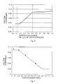
- the film thickness ratio in each combination determined by the expression (1) is shown in Table 2.
- Table 2 Surface roughness Ra ( ⁇ m) Film thickness ratio Friction coefficient 1.0 0.05 0.092 0.5 0.2 0.088 0.4 0.4 0.07 0.15 0.7 0.04
- Ra is the surface roughness Ra ( ⁇ m) of the distal end surface 28 of each test piece 27, and Ra' is the surface roughness of the columnar surface 30 of each roller 29, that is, 0.0945 ⁇ m.
- Table 2 shows a relation among the surface roughness Ra of the distal end surface 28 of each of the test pieces 27 as models of the tooth surfaces of the teeth of the worm wheel, the film thickness ratio determined by the expression (1) and the friction coefficient between the tooth surfaces of the two gear components, which was determined from the measurement.
- a relation between the film thickness ratio and the friction coefficient is plotted by a symbol ( ⁇ ) in FIG. 7 .
- a solid line shows a theoretical relation between the film thickness ratio and the friction coefficient. It has been confirmed that results of measurement shown in Table 2 substantially coincide with corresponding theoretical values.
Landscapes
- Engineering & Computer Science (AREA)
- Mechanical Engineering (AREA)
- General Engineering & Computer Science (AREA)
- Chemical & Material Sciences (AREA)
- Combustion & Propulsion (AREA)
- Transportation (AREA)
- Physics & Mathematics (AREA)
- Electromagnetism (AREA)
- Thermal Sciences (AREA)
- Gears, Cams (AREA)
- Power Steering Mechanism (AREA)
- Gear Transmission (AREA)
Applications Claiming Priority (1)
| Application Number | Priority Date | Filing Date | Title |
|---|---|---|---|
| JP2012148702A JP2014009789A (ja) | 2012-07-02 | 2012-07-02 | 電動パワーステアリング装置 |
Publications (2)
| Publication Number | Publication Date |
|---|---|
| EP2682327A2 true EP2682327A2 (de) | 2014-01-08 |
| EP2682327A3 EP2682327A3 (de) | 2015-04-22 |
Family
ID=48782878
Family Applications (1)
| Application Number | Title | Priority Date | Filing Date |
|---|---|---|---|
| EP20130174095 Withdrawn EP2682327A3 (de) | 2012-07-02 | 2013-06-27 | Elektrisches Servolenksystem |
Country Status (4)
| Country | Link |
|---|---|
| US (1) | US20140000401A1 (de) |
| EP (1) | EP2682327A3 (de) |
| JP (1) | JP2014009789A (de) |
| CN (1) | CN103523078A (de) |
Cited By (1)
| Publication number | Priority date | Publication date | Assignee | Title |
|---|---|---|---|---|
| DE102020104122B4 (de) | 2020-02-18 | 2026-01-29 | Audi Aktiengesellschaft | Verfahren zur Herstellung eines Getriebes |
Families Citing this family (4)
| Publication number | Priority date | Publication date | Assignee | Title |
|---|---|---|---|---|
| DE102013020599B4 (de) * | 2013-12-13 | 2020-06-10 | Thyssenkrupp Presta Ag | Verfahren zum Einlaufen eines Schneckenradgetriebes |
| BR112017013551B1 (pt) | 2014-12-26 | 2020-11-03 | Kyodo Yushi Co., Ltd. | Composição de graxa para resinas lubrificantes, mecanismo de engrenagem de redução, e, dispositivo de direção assistida elétrica |
| JP6566245B2 (ja) * | 2015-05-21 | 2019-08-28 | 株式会社ジェイテクト | ウォーム減速機およびステアリング装置 |
| JP7251118B2 (ja) * | 2018-11-28 | 2023-04-04 | セイコーエプソン株式会社 | 歯車装置およびロボット |
Citations (4)
| Publication number | Priority date | Publication date | Assignee | Title |
|---|---|---|---|---|
| US3311555A (en) * | 1961-09-29 | 1967-03-28 | Niemann | Method for running-in gear wheels and an agent therefor |
| JP2005214339A (ja) | 2004-01-30 | 2005-08-11 | Nsk Ltd | 減速機構及びそれを備えた電動パワーステアリング装置 |
| JP2006044306A (ja) * | 2004-07-30 | 2006-02-16 | Nsk Ltd | 電動パワーステアリング装置 |
| JP2009202754A (ja) * | 2008-02-28 | 2009-09-10 | Nsk Ltd | 電動パワーステアリング装置用減速ギヤ機構 |
Family Cites Families (14)
| Publication number | Priority date | Publication date | Assignee | Title |
|---|---|---|---|---|
| US4920703A (en) * | 1986-06-04 | 1990-05-01 | Koganei Seiki Seisakusho | Method and apparatus for finishing a tooth surface of a gear |
| DE3707664C1 (de) * | 1987-03-10 | 1988-10-13 | Liebherr Verzahntech Gmbh | Werkzeugmaschine zum Feinbearbeiten der Zahnflanken von vorverzahnten Zahnraedern |
| JP3765208B2 (ja) * | 1999-09-08 | 2006-04-12 | 株式会社ジェイテクト | 電動式舵取装置 |
| JP2001108024A (ja) * | 1999-10-06 | 2001-04-20 | Koyo Seiko Co Ltd | 電動パワーステアリング装置 |
| JP4331863B2 (ja) * | 2000-05-09 | 2009-09-16 | 株式会社ショーワ | 樹脂製歯車の製造方法 |
| US6732606B1 (en) * | 2000-06-30 | 2004-05-11 | Eaton Corporation | Polished gear surfaces |
| JP3650726B2 (ja) * | 2000-08-08 | 2005-05-25 | 光洋精工株式会社 | 電動パワーステアリング装置 |
| JP2002257211A (ja) * | 2001-02-28 | 2002-09-11 | Koyo Seiko Co Ltd | 歯車の製造方法及び歯車のなじみ運転装置 |
| JP2002213576A (ja) * | 2001-11-12 | 2002-07-31 | Honda Motor Co Ltd | 電動パワーステアリング装置 |
| US7360468B2 (en) * | 2003-03-19 | 2008-04-22 | Nsk Ltd. | Electric power steering device and resin gear used for the same |
| EP1646477B1 (de) * | 2003-05-30 | 2009-04-29 | REM Technologies, Inc. | Feinstbearbeitung von grossen planetengetriebesystemen |
| JP4902534B2 (ja) * | 2005-05-25 | 2012-03-21 | 旭有機材工業株式会社 | 電動パワーステアリング装置用樹脂歯車及びそれを備えた電動パワーステアリング装置 |
| US7686734B2 (en) * | 2007-02-12 | 2010-03-30 | Gm Global Technology Operations, Inc. | Apparatus and method of using a hardness differential and surface finish on mating hard gears |
| JP5305123B2 (ja) * | 2007-11-28 | 2013-10-02 | Ntn株式会社 | 歯車 |
-
2012
- 2012-07-02 JP JP2012148702A patent/JP2014009789A/ja active Pending
-
2013
- 2013-06-24 US US13/925,056 patent/US20140000401A1/en not_active Abandoned
- 2013-06-26 CN CN201310259540.7A patent/CN103523078A/zh active Pending
- 2013-06-27 EP EP20130174095 patent/EP2682327A3/de not_active Withdrawn
Patent Citations (4)
| Publication number | Priority date | Publication date | Assignee | Title |
|---|---|---|---|---|
| US3311555A (en) * | 1961-09-29 | 1967-03-28 | Niemann | Method for running-in gear wheels and an agent therefor |
| JP2005214339A (ja) | 2004-01-30 | 2005-08-11 | Nsk Ltd | 減速機構及びそれを備えた電動パワーステアリング装置 |
| JP2006044306A (ja) * | 2004-07-30 | 2006-02-16 | Nsk Ltd | 電動パワーステアリング装置 |
| JP2009202754A (ja) * | 2008-02-28 | 2009-09-10 | Nsk Ltd | 電動パワーステアリング装置用減速ギヤ機構 |
Cited By (1)
| Publication number | Priority date | Publication date | Assignee | Title |
|---|---|---|---|---|
| DE102020104122B4 (de) | 2020-02-18 | 2026-01-29 | Audi Aktiengesellschaft | Verfahren zur Herstellung eines Getriebes |
Also Published As
| Publication number | Publication date |
|---|---|
| JP2014009789A (ja) | 2014-01-20 |
| US20140000401A1 (en) | 2014-01-02 |
| EP2682327A3 (de) | 2015-04-22 |
| CN103523078A (zh) | 2014-01-22 |
Similar Documents
| Publication | Publication Date | Title |
|---|---|---|
| EP2682327A2 (de) | Elektrisches Servolenksystem | |
| JP5999423B2 (ja) | 電動パワーステアリング装置 | |
| EP2431634B1 (de) | Schneckenantrieb | |
| EP1207095B1 (de) | Elektrische Servolenkung und dafür benutztes Zahnradherstellungsverfahren | |
| WO2013122158A1 (ja) | 電動リニアアクチュエータ | |
| WO2005000662A1 (ja) | 電動パワーステアリング装置 | |
| WO2014058049A1 (ja) | 電動リニアアクチュエータ | |
| EP3441645B1 (de) | Schneckenreduktionsgetriebe | |
| US20200290113A1 (en) | Shaft for steering device, method of manufacturing shaft for steering device, and electric power steering device | |
| CN110650883B (zh) | 转向装置用轴、转向装置用轴的制造方法以及电动动力转向装置 | |
| JP2023108848A (ja) | ステアリング装置用ラック軸およびその製造方法、ならびにステアリング装置 | |
| JP2009051354A (ja) | 電動パワーステアリング装置 | |
| EP2626594B1 (de) | Schneckenrad | |
| CN102401108B (zh) | 齿轮装置及轴部件的制造方法 | |
| JP5557006B2 (ja) | 電動パワーステアリング装置の製造方法 | |
| CN111609113A (zh) | 用于转向系统蜗轮蜗杆减速装置的蜗轮及减速装置 | |
| JP2009228696A (ja) | 伝達機構、伝達機構の製造方法および車両用操舵装置 | |
| JP2013087796A (ja) | ウォーム減速機 | |
| JP5544281B2 (ja) | 減速ギヤの製造方法 | |
| JP2012117649A (ja) | 減速機、これを備える電動パワーステアリング装置、ならびに減速機の製造方法 | |
| CN106369041B (zh) | 一种精密减速机偏心轴及精密减速机 | |
| JP2012106560A (ja) | 電動パワーステアリング装置 | |
| JP2005240959A (ja) | 電動パワーステアリング装置及びその製造方法 | |
| JP5757100B2 (ja) | ウォームホイール及びその製造方法並びに電動パワーステアリング装置 | |
| JPS594848Y2 (ja) | リサ−キュレイテイングボ−ル式ステアリングギア装置用ウオ−ムシヤフト |
Legal Events
| Date | Code | Title | Description |
|---|---|---|---|
| PUAI | Public reference made under article 153(3) epc to a published international application that has entered the european phase |
Free format text: ORIGINAL CODE: 0009012 |
|
| AK | Designated contracting states |
Kind code of ref document: A2 Designated state(s): AL AT BE BG CH CY CZ DE DK EE ES FI FR GB GR HR HU IE IS IT LI LT LU LV MC MK MT NL NO PL PT RO RS SE SI SK SM TR |
|
| AX | Request for extension of the european patent |
Extension state: BA ME |
|
| PUAL | Search report despatched |
Free format text: ORIGINAL CODE: 0009013 |
|
| AK | Designated contracting states |
Kind code of ref document: A3 Designated state(s): AL AT BE BG CH CY CZ DE DK EE ES FI FR GB GR HR HU IE IS IT LI LT LU LV MC MK MT NL NO PL PT RO RS SE SI SK SM TR |
|
| AX | Request for extension of the european patent |
Extension state: BA ME |
|
| RIC1 | Information provided on ipc code assigned before grant |
Ipc: F16H 1/06 20060101ALI20150316BHEP Ipc: F16H 55/06 20060101ALI20150316BHEP Ipc: B62D 5/00 20060101ALI20150316BHEP Ipc: F16H 55/22 20060101ALI20150316BHEP Ipc: B62D 5/04 20060101AFI20150316BHEP |
|
| 17P | Request for examination filed |
Effective date: 20151009 |
|
| RBV | Designated contracting states (corrected) |
Designated state(s): AL AT BE BG CH CY CZ DE DK EE ES FI FR GB GR HR HU IE IS IT LI LT LU LV MC MK MT NL NO PL PT RO RS SE SI SK SM TR |
|
| 17Q | First examination report despatched |
Effective date: 20161108 |
|
| STAA | Information on the status of an ep patent application or granted ep patent |
Free format text: STATUS: THE APPLICATION IS DEEMED TO BE WITHDRAWN |
|
| 18D | Application deemed to be withdrawn |
Effective date: 20170321 |