EP2682328A1 - Radaufhängung für ein lenkbares Rad eines Fahrzeuges - Google Patents
Radaufhängung für ein lenkbares Rad eines Fahrzeuges Download PDFInfo
- Publication number
- EP2682328A1 EP2682328A1 EP13174974.9A EP13174974A EP2682328A1 EP 2682328 A1 EP2682328 A1 EP 2682328A1 EP 13174974 A EP13174974 A EP 13174974A EP 2682328 A1 EP2682328 A1 EP 2682328A1
- Authority
- EP
- European Patent Office
- Prior art keywords
- wheel
- hinge means
- swivel
- holder
- wheel holder
- Prior art date
- Legal status (The legal status is an assumption and is not a legal conclusion. Google has not performed a legal analysis and makes no representation as to the accuracy of the status listed.)
- Withdrawn
Links
Images



Classifications
-
- B—PERFORMING OPERATIONS; TRANSPORTING
- B60—VEHICLES IN GENERAL
- B60G—VEHICLE SUSPENSION ARRANGEMENTS
- B60G3/00—Resilient suspensions for a single wheel
- B60G3/18—Resilient suspensions for a single wheel with two or more pivoted arms, e.g. parallelogram
- B60G3/20—Resilient suspensions for a single wheel with two or more pivoted arms, e.g. parallelogram all arms being rigid
-
- B—PERFORMING OPERATIONS; TRANSPORTING
- B62—LAND VEHICLES FOR TRAVELLING OTHERWISE THAN ON RAILS
- B62D—MOTOR VEHICLES; TRAILERS
- B62D7/00—Steering linkage; Stub axles or their mountings
- B62D7/06—Steering linkage; Stub axles or their mountings for individually-pivoted wheels, e.g. on king-pins
- B62D7/08—Steering linkage; Stub axles or their mountings for individually-pivoted wheels, e.g. on king-pins the pivotal axes being situated in a single plane transverse to the longitudinal centre line of the vehicle
-
- B—PERFORMING OPERATIONS; TRANSPORTING
- B62—LAND VEHICLES FOR TRAVELLING OTHERWISE THAN ON RAILS
- B62D—MOTOR VEHICLES; TRAILERS
- B62D7/00—Steering linkage; Stub axles or their mountings
- B62D7/20—Links, e.g. track rods
-
- B—PERFORMING OPERATIONS; TRANSPORTING
- B60—VEHICLES IN GENERAL
- B60G—VEHICLE SUSPENSION ARRANGEMENTS
- B60G2200/00—Indexing codes relating to suspension types
- B60G2200/10—Independent suspensions
- B60G2200/14—Independent suspensions with lateral arms
-
- B—PERFORMING OPERATIONS; TRANSPORTING
- B60—VEHICLES IN GENERAL
- B60G—VEHICLE SUSPENSION ARRANGEMENTS
- B60G2200/00—Indexing codes relating to suspension types
- B60G2200/40—Indexing codes relating to the wheels in the suspensions
- B60G2200/422—Driving wheels or live axles
-
- B—PERFORMING OPERATIONS; TRANSPORTING
- B60—VEHICLES IN GENERAL
- B60G—VEHICLE SUSPENSION ARRANGEMENTS
- B60G2200/00—Indexing codes relating to suspension types
- B60G2200/40—Indexing codes relating to the wheels in the suspensions
- B60G2200/44—Indexing codes relating to the wheels in the suspensions steerable
-
- B—PERFORMING OPERATIONS; TRANSPORTING
- B60—VEHICLES IN GENERAL
- B60G—VEHICLE SUSPENSION ARRANGEMENTS
- B60G2204/00—Indexing codes related to suspensions per se or to auxiliary parts
- B60G2204/10—Mounting of suspension elements
- B60G2204/18—Mounting of vehicle engines
- B60G2204/182—Electric motor on wheel support
-
- B—PERFORMING OPERATIONS; TRANSPORTING
- B60—VEHICLES IN GENERAL
- B60G—VEHICLE SUSPENSION ARRANGEMENTS
- B60G2204/00—Indexing codes related to suspensions per se or to auxiliary parts
- B60G2204/40—Auxiliary suspension parts; Adjustment of suspensions
- B60G2204/421—Pivoted lever mechanisms for mounting suspension elements, e.g. Watt linkage
-
- B—PERFORMING OPERATIONS; TRANSPORTING
- B60—VEHICLES IN GENERAL
- B60G—VEHICLE SUSPENSION ARRANGEMENTS
- B60G2204/00—Indexing codes related to suspensions per se or to auxiliary parts
- B60G2204/40—Auxiliary suspension parts; Adjustment of suspensions
- B60G2204/422—Links for mounting suspension elements
- B60G2204/4222—Links for mounting suspension elements for movement on predefined locus of, e.g. the wheel center
-
- B—PERFORMING OPERATIONS; TRANSPORTING
- B60—VEHICLES IN GENERAL
- B60G—VEHICLE SUSPENSION ARRANGEMENTS
- B60G2300/00—Indexing codes relating to the type of vehicle
- B60G2300/14—Buses
-
- B—PERFORMING OPERATIONS; TRANSPORTING
- B60—VEHICLES IN GENERAL
- B60G—VEHICLE SUSPENSION ARRANGEMENTS
- B60G2300/00—Indexing codes relating to the type of vehicle
- B60G2300/50—Electric vehicles; Hybrid vehicles
Definitions
- the present invention relates to a wheel suspension of a steerable wheel, the wheel suspension comprising a wheel holder with which a wheel, at least during operation, is rotatably connected around a rotation axis, the wheel holder being connectable to the vehicle frame in a swiveling manner, at least one track body being coupled to the wheel holder, capable of and adapted to impose a deflection around a swivel axis to the wheel holder, when energized.
- Such a wheel suspension is, for example, known from American patent USP 4.799.703 and is used on a large scale in a steering assembly for motor vehicles, such as for example cars, vans, buses and lorries.
- the wheel is usually assembled on a wheel carrier, which extends from the wheel holder through the interposition of a suitable bearing.
- the wheel holder is connected to the vehicle frame in a swiveling manner to allow the wheel to adopt another position for cornering.
- This swivelable connection between the wheel holder and the vehicle frame arises in the known wheel suspension as a result of a connector, often in the form of a so-called spindle piece with a ball joint which accordingly is heavily sized to be able to resist a drive load.
- the present invention aims, amongst other things, to provide for a wheel suspension which leaves space free within a wheel space of the wheel holder, so that this space is available, for example, for the driving of the wheel.
- a wheel suspension of the type described in the opening paragraph according to the invention is characterized in that the at least one track body comprises a first track body and a second track body, which are, through the interposition of first hinge means, each rotatably connected to respectively a first swivel body, a second swivel body and the wheel holder, that the first swivel body and the second swivel body are rotatably connectable to the vehicle frame through the interposition of respective further hinge means, that the first hinge means and the further hinge means are at least substantially in a first direction, at least in projection, at least substantially in alignment with one another, that the hinge means of or with each of both swivel bodies and of or with the wheel holder are at least substantially in a second direction, at least in projection, at least substantially in alignment with one another, that a supporting point of the wheel and the further hinge means are at least substantially in the first direction, at least in projection, at least substantially in alignment with one another and that the supporting point of the wheel and the further hinge means
- This wheel suspension allows actuation of the swivel bodies with the track bodies articulated thereto. This actuation is imposed, via the track bodies, on the wheel holder, to which the wheel is fixed, which turns, as it were, around a virtual king pin axis.
- the wheel suspension according to the invention thereby allows the track bodies to engage with the wheel holder outside a wheel space, so that space remains available inside the wheel for say a driving of the wheel.
- the first hinge means comprise ball hinge means.
- Ball hinge means allow a free rotation in space around three imaginary mutually orthogonal rotation axes.
- the first hinge means connect the track bodies to the swivel bodies and thus provide freedom of movement in all directions. This freedom of movement is particularly provided outside a plane spanned by the swivel bodies and track bodies, such that the whole, perpendicular to that plane, retains a degree of freedom.
- a further particular embodiment of the wheel suspension according to the invention is characterized in that the second hinge means comprise line hinge means.
- Such line hinge means allow a rotation of the first swivel body in a flat plane around an imaginary hinge axis, which is translated into a corresponding swiveling of the wheel around the first swivel axis. Apart from this swiveling the line hinges provide, save for a certain clearance, a rigid connection which leads to stability of the whole.
- a preferred embodiment of the wheel suspension according to the invention is characterized in that the first hinge means comprise ball hinge means with the first swivel body, that the further hinge means of the first swivel body comprise a line hinge with a substantially vertical swivel axis, and that the second swivel body is connected to the vehicle frame by guide means which impose on the further hinge means of the second swivel body a trajectory at least almost in accordance with a circular arc.
- the vertically orientated line hinge of the first swivel body only allows the first swivel body to swivel in a substantially horizontal plane.
- the trajectory into which the further hinge means of the second swivel body are thus forced is located in a plane that at least by approximation is perpendicular to the driving direction.
- a centre of the circular arc at least by approximation coincides with the further hinge means of the first swivel body.
- the wheel suspension according to the invention is characterized in that the guide means comprise a stabilization body, which is connected to the second swivel body through the interposition of first ball hinge means and is connectable to the vehicle frame through the interposition of second ball hinge means, the first and second ball hinge means, viewed in a driving direction, and at least in projection, being in alignment with each other.
- the first ball hinge means can trace at least almost a circular movement around the connecting line between the further hinge means of the first swivel body and the second hinge means of the stabilization body, the circular movement at least almost coinciding with a vertical, linear movement during small wheel deflections.
- the stabilization body is further tasked with transferring brake- and drive forces from the wheels via the wheel holders, the track bodies and the second swivel body to the vehicle frame, and vice versa.
- a preferred embodiment of the wheel suspension according to the invention is characterized in that the wheel holder comprises a first wheel holder part on a first side of a wheel space, as well as a second wheel holder part on a second, viewed in a driving direction, facing side of the wheel space, and that the first and the second track body are rotatably connected on both sides of the wheel space through the interposition of ball hinge means to respectively the first wheel holder part and the second wheel holder part of the wheel holder.
- the wheel suspension thus leaves a wheel space completely free at the location of the wheel, so that, for example, a driving of the wheel or vehicle components otherwise connected to the wheel can be advantageously provided for, such as for instance a braking device.
- a further particular embodiment of the wheel suspension according to the invention is characterized in that the wheel holder comprises a central part with which the wheel is rotatably connectable around a rotation axis, that the first wheel holder piece and the second wheel holder piece each comprise an angulated wheel holder arm which on the one hand extends radially from the central part of the wheel holder and on the other hand reaches around the wheel space with a distal end, where a track body is connected to it.
- the wheel suspension according to the invention is characterized in that the wheel holder comprises a third wheel holder part between the first wheel holder part and the second wheel holder part, which extends above the wheel space and is connectable to the vehicle frame through the interposition of ball hinge means and guide means, the ball hinge means being located at least almost in a vertical plane through the supporting point of the wheel, and that the guide means impose upon the wheel holder at least substantially a linear trajectory.
- the third wheel holder part which is connectable to the vehicle frame through the interposition of a ball hinge, is forced by the guide means into an at least by approximation straight, substantially vertical line which goes through the supporting point of the wheel with the road.
- Said guide means may advantageously comprise a so-called Mc Pherson wheel strut. This consists of a mainly vertically placed guiding which is connected to the vehicle frame via ball hinge means.
- the guide means comprise as an alternative that the guide means of the wheel holder can be carried out as an at least by approximation horizontally placed stabilization body which is connected to the third wheel holder piece through interposition of a ball hinge means and is connected to the vehicle frame through the interposition of a line hinge, of which a hinge line is located at least by approximation in the driving direction.
- the weight of the frame and the other vehicle parts are transferred to the wheel carrier and the wheel via spring and damping means.
- the wheel holder is connectable in an axially movable manner to the vehicle frame through the interposition of spring means.
- spring means comprise, for example, a helical spring with a shock absorber or air suspension and provide for a significant increase in riding comfort, which is particularly advantageous for passenger transport, besides a relieving of the whole construction if the wheel is subjected to vertically directed forces.
- a special embodiment of the wheel suspension according to the invention in this context is characterized in that the wheel holder comprises a wheel motor, which at least during operation drives the wheel, whereby the wheel is directly driven by a satellite motor. Not only does this avoid the construction of a driving line from a central motor of the vehicle, it also thus keeps driving loss to a minimum.
- the wheel suspension according to the invention is characterized in that the wheel motor comprises an electric motor. Due to the enormous torque at low speeds an electric motor is eminently suited to drive a wheel of a vehicle. Moreover, the feeding of an electric motor can be realized elegantly by means of an electric cable connection from a battery (pack) or generator elsewhere on board the vehicle. In a further special embodiment such a compact electric motor is used that the wheel motor is at least partly located in the wheel.
- a further special preferred embodiment of the wheel suspension according to the invention is characterized in that the wheel holder comprises a central part with which the wheel is rotatably connectable around a rotation axis, as well as a set of angulated wheel holder arms which extend radially from the central part of the wheel holder and reach around a wheel space with a distal end, the track bodies each being connected to a distal end of a wheel holder arm.
- the track bodies thus engage with the wheel holder outside the wheel space, so that at the level of the central part thereof no space is occupied by the wheel suspension.
- This space can thus advantageously be used for the placement of, for example, the previously described satellite motor.
- a further special embodiment of the wheel suspension according to the invention comprises for this purpose a second corresponding wheel holder which is connectable to the vehicle frame in a swivelable manner on a facing side of the vehicle frame.
- a further special preferred embodiment of the wheel suspension according to the invention is characterized in that both wheel holders are coupled to a common swivel body. Thus an extra swivel body is avoided and it is ensured that both wheels have a deflection imposed upon them synchronously.
- An alternative embodiment of the wheel suspension according to the invention is, however, characterized in that both wheel holders are each connected to an own swivel body and that the swivel bodies of both wheel holders are coupled to each other by means of a coupling body, the coupling body being rotatably connected to each of the swivel bodies outside the line of the first hinge means of or to the swivel body.
- the coupling between both swivel bodies outside a line of the hinge connections with the swivel bodies provides for a coordinated uneven deflection of both wheels, which will benefit the curve behavior of the vehicle.
- An outer wheel can thus have a greater turning circle imposed upon it than an inner wheel, taking into account the mutual distance between the wheels, so that the vehicle will not "wrench" as much in a turn.
- a further special embodiment of the wheel suspension in this respect is characterized in that the swivel bodies extend with a steered wheel from a wheel axle of the vehicle and that the vehicle comprises a further wheel axle, from which a set of non-steered wheels extends and that respective rotation axes of the steered wheels, when inclined, intersect each other at least almost in the prolongation of the further wheel axle of the vehicle. Accordingly the wheel suspension is conducive to satisfying the so-called Ackermann-principle, which demonstrates on theoretical grounds that wrenching in a turn is kept to a minimum.
- a further special embodiment of the wheel suspension according to the invention in this context is characterized in that the swivel bodies extend with a steered wheel from a wheel axle of the vehicle and that the vehicle comprises a further wheel axle from which a corresponding further set of steered wheels extends and that respective rotation axes of the steered wheels, when inclined, intersect each other at least almost on an imaginary axis halfway between both wheel axes of the vehicle. Also in the case of a thus simultaneously steered further wheel axle a wrenching in the turns can in this way be limited and moreover the turning circle is reduced.
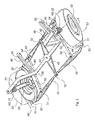
- FIG. 1 shows an example of an embodiment of a wheel suspension according to the invention.
- the wheel suspension is used doubly for both shown, steered wheels 10 of a vehicle of which a part 20 of a vehicle frame is represented in the figure.
- This example concerns a part of an electric bus, but the wheel suspension can also be used on other vehicles, either electrically driven or not.
- the wheels 10 are each rotatably assembled around a rotation axis on a wheel holder 30 which is connected to the vehicle frame 20 in a swivelable manner around an imaginary swivel axes through the interposition of the wheel suspension.
- the wheel holder 30 comprises a central part 35 from which a set of angulated arms 31, 32, 33 extends radially.
- the wheel holder arms 31, 32, 33 each reach with an end around the wheel which is free to rotate in a wheel space falling therein.
- the wheel suspension comprises on either side of the wheel axle shown in the figure a first track body 41 and a second track body 42, which through the interposition of hinge means in the form of ball hinges 51, 52 is rotatably connected on one hand to an end of one of the wheel holder arms 31, 32 and on the other hand are coupled to a first swivel body 43.
- the swivel body 43 is articulated to the vehicle frame 20 through the interposition of further hinge means in the form of a line hinge 53.
- the first swivel body 43 in this example of an embodiment is shared by the wheel suspensions of both wheels, so that a deflection thereof will be evenly transferred to both wheels.
- the wheel suspension further comprises a second swivel body 44 which extends between both track bodies 41, 42 and through the interposition of hinge means in the form of further line hinges 54 are rotatably connected to them.
- the further swivel bodies 44 are each coupled to the vehicle frame through the interposition of a stabilization body 45.
- the stabilization body 45 is on the one hand connected at a point of rotation to the swivel body 44 through the interposition of further hinge means in the form of ball hinges 55, 56, so that that will thus be rotatable there, and on the other hand coupled rotatably to a part of the vehicle frame 20.
- the stabilization body deprives the whole of a degree of freedom of movement around a rotation axis of the wheel, which particularly benefits a (torsion) stability when accelerating or slowing down.
- the individual hinge means 51..55 are positioned and the different parts of the suspension sized in such a manner that the hinge means 51, 52, 54 of or with both track bodies 41, 42 mutually are at least almost in alignment in substantially a first direction.
- the hinge means 52, 53, 54, 55 of or with each of both swivel bodies 43, 44 of each suspension are substantially in a second direction also at least almost in alignment with each other.
- a supporting point S of the wheel is substantially in the first direction R1 at least almost in alignment with the hinge means 51, 52 of or with the wheel holders and substantially in the second direction R2 at least almost in alignment with the hinge means 53, 55 between the swivel bodies 43, 44 and the vehicle frame 20.
- the hinge means lie at the vertices of imaginary parallelograms with in pairs mutually almost parallel sides, which are stretched or enclosed by one or more of the track bodies 41, 42 and the swivel bodies 43, 44 together with an imaginary line through the rotation points 51, 52 and the supporting point S of the wheel.
- the first and second direction of the hinge means within the individual parts, such as the track bodies and swivel bodies are indicated schematically with interrupted centre lines. Although these lines are not completely parallel to each other, due to a king pin inclination and Ackermann principle which are also pursued, nevertheless a first direction in a width of the vehicle and second direction in a driving direction of the vehicle can substantially be distinguished in them.
- wheel suspension mainly behaves like a normal king pin axis suspension with king pin axis connection on the inside of the wheel near the supporting point S, a substantial space is kept free in the shown wheel suspension on the inside of the wheel.
- This space can be used advantageously, for example for a wheel motor 80 such as represented in the figure.
- This example concerns an electric motor which drives the wheel 10 directly and is assembled inside the wheel to a large extent.
- the motor 80 receives power via connection cables not shown in further detail from a battery storage , which is placed elsewhere in the vehicle frame, also not shown in more detail.
- the motor 80 is connected to an electronic steering connection to receive control signals from it.
- space is available on location to potentially place braking means directly at the wheel.
- a third arm 33 of the wheel holder is connected to the vehicle frame 20 in an axially moveable manner through the interposition of suitable spring means.
- the spring means may consist of a shock absorber 60, usually with a helical spring 61 around or next to it (see also figure 3 ) or else are formed by air suspension with in that case bellows between the third wheel holder arm and the vehicle frame.
- the wheel suspension can also be equipped with a separate first swivel body.
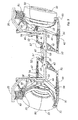
- An example of such an embodiment is displayed in figure 3-5 .
- the coupling body is rotatably connected to both swivel bodies through the interposition of further hinge means 57 in the form of ball hinges.
- the ball hinges 57 are located outside the line which is stretched by the remaining hinge means 51, 52, 53 of or with the swivel bodies, see also figure 4 .
- the effect of this is shown in figure 5 and results in the rotation axes of both wheels at least almost intersecting each other in a turn at the level of a point P on or in the prolongation of a further wheel axle of the vehicle, from which a set of non-steered wheels extends.
- the wheel suspension complies with the so-called Ackermann-principle that aims to counteract a "wrenching" of the wheels in a turn.
- the coupling body 47 is sized and assembled in such a way that the aforementioned intersection P is positioned centrally under the vehicle about halfway between both wheel axles.
- the various hinge means with or of the track bodies, swivel bodies and wheel holder mutually are at least almost in alignment with each other in this embodiment, such as is schematically shown in the top view of figure 4 with centre lines.
- a first direction in a width of the vehicle can be substantially distinguished from a second direction mainly directed in a driving direction, whereby the hinge means of or with the swivel bodies and wheel holder are at least almost substantially in alignment with each other.
- the hinge means with the track bodies are substantially in the first direction almost mutually in alignment with each other.
Landscapes
- Engineering & Computer Science (AREA)
- Mechanical Engineering (AREA)
- Chemical & Material Sciences (AREA)
- Combustion & Propulsion (AREA)
- Transportation (AREA)
- Vehicle Body Suspensions (AREA)
Applications Claiming Priority (1)
| Application Number | Priority Date | Filing Date | Title |
|---|---|---|---|
| NL2009111A NL2009111C2 (nl) | 2012-07-03 | 2012-07-03 | Wielophanging voor een sturend wiel van een voertuig. |
Publications (1)
| Publication Number | Publication Date |
|---|---|
| EP2682328A1 true EP2682328A1 (de) | 2014-01-08 |
Family
ID=46939949
Family Applications (1)
| Application Number | Title | Priority Date | Filing Date |
|---|---|---|---|
| EP13174974.9A Withdrawn EP2682328A1 (de) | 2012-07-03 | 2013-07-03 | Radaufhängung für ein lenkbares Rad eines Fahrzeuges |
Country Status (2)
| Country | Link |
|---|---|
| EP (1) | EP2682328A1 (de) |
| NL (1) | NL2009111C2 (de) |
Cited By (1)
| Publication number | Priority date | Publication date | Assignee | Title |
|---|---|---|---|---|
| CN110546060A (zh) * | 2017-05-08 | 2019-12-06 | 宝马股份公司 | 用于机动车的转向组件和机动车 |
Citations (15)
| Publication number | Priority date | Publication date | Assignee | Title |
|---|---|---|---|---|
| DE868117C (de) * | 1951-05-11 | 1953-02-23 | Bayerische Motoren Werke Ag | Unabhaengige Aufhaengung der gelenkten Vorderraeder von Kraftfahrzeugen |
| US2863518A (en) * | 1957-06-25 | 1958-12-09 | Pellizzetti Italo | Motor vehicle equipped with wheels capable of steering substantially through 90 deg.from their straight drive position |
| US3302739A (en) * | 1963-11-19 | 1967-02-07 | Goodman Mfg Co | Shuttle cars with six driven wheels |
| US3587767A (en) * | 1968-12-19 | 1971-06-28 | Lockheed Aircraft Corp | Steering assembly for a vehicle |
| DE2535670A1 (de) * | 1975-08-09 | 1977-02-17 | Porsche Ag | Radaufhaengung fuer die gelenkten raeder von kraftfahrzeugen |
| DE3703198C1 (de) * | 1987-02-03 | 1988-05-11 | Bayerische Motoren Werke Ag | Radaufhaengung fuer lenkbare Hinterraeder von mit Vorderradlenkung ausgestatteten Kraftfahrzeugen,insbesondere Personenkraftwagen |
| DE19840135A1 (de) * | 1998-09-03 | 2000-03-09 | Volkswagen Ag | Aufhängung einer Starrachse für ein Kraftfahrzeug |
| EP1426203A1 (de) * | 2002-12-03 | 2004-06-09 | Ford Global Technologies, Inc. | Radaufhängungs-Anordnung, Lenkgestänge-Anordnung und Verfahren zum Bereitstellen eines veränderlichen Radstandes |
| EP1500575A2 (de) * | 2003-07-23 | 2005-01-26 | Nissan Motor Company, Limited | Fahrzeuglenksystem |
| US20060027986A1 (en) * | 2004-08-03 | 2006-02-09 | Ziech James F | Method and apparatus for a rear wheel steer system for a vehicle |
| US20060214408A1 (en) * | 2003-01-28 | 2006-09-28 | Davey Garth B | Steerable single wheel unit for trailers |
| JP2007008285A (ja) * | 2005-06-29 | 2007-01-18 | Toyota Motor Corp | 車両のステアリング装置 |
| JP2008174056A (ja) * | 2007-01-17 | 2008-07-31 | Toyota Motor Corp | 操舵輪用車輪懸架装置 |
| FR2940191A1 (fr) * | 2008-12-23 | 2010-06-25 | Peugeot Citroen Automobiles Sa | Essieu destine au support d'une roue directrice relie a la structure d'un vehicule par une pluralite de bras. |
| US20110089657A1 (en) * | 2007-11-22 | 2011-04-21 | Toyota Jidosha Kabushiki Kaisha | Vehicle steering device |
-
2012
- 2012-07-03 NL NL2009111A patent/NL2009111C2/nl not_active IP Right Cessation
-
2013
- 2013-07-03 EP EP13174974.9A patent/EP2682328A1/de not_active Withdrawn
Patent Citations (16)
| Publication number | Priority date | Publication date | Assignee | Title |
|---|---|---|---|---|
| DE868117C (de) * | 1951-05-11 | 1953-02-23 | Bayerische Motoren Werke Ag | Unabhaengige Aufhaengung der gelenkten Vorderraeder von Kraftfahrzeugen |
| US2863518A (en) * | 1957-06-25 | 1958-12-09 | Pellizzetti Italo | Motor vehicle equipped with wheels capable of steering substantially through 90 deg.from their straight drive position |
| US3302739A (en) * | 1963-11-19 | 1967-02-07 | Goodman Mfg Co | Shuttle cars with six driven wheels |
| US3587767A (en) * | 1968-12-19 | 1971-06-28 | Lockheed Aircraft Corp | Steering assembly for a vehicle |
| DE2535670A1 (de) * | 1975-08-09 | 1977-02-17 | Porsche Ag | Radaufhaengung fuer die gelenkten raeder von kraftfahrzeugen |
| DE3703198C1 (de) * | 1987-02-03 | 1988-05-11 | Bayerische Motoren Werke Ag | Radaufhaengung fuer lenkbare Hinterraeder von mit Vorderradlenkung ausgestatteten Kraftfahrzeugen,insbesondere Personenkraftwagen |
| US4799703A (en) | 1987-02-03 | 1989-01-24 | Bayerische Motoren Werke Aktiengesellschaft | Wheel suspension for rear wheels of motor vehicles equipped with front wheel steering, especially passenger motor vehicles |
| DE19840135A1 (de) * | 1998-09-03 | 2000-03-09 | Volkswagen Ag | Aufhängung einer Starrachse für ein Kraftfahrzeug |
| EP1426203A1 (de) * | 2002-12-03 | 2004-06-09 | Ford Global Technologies, Inc. | Radaufhängungs-Anordnung, Lenkgestänge-Anordnung und Verfahren zum Bereitstellen eines veränderlichen Radstandes |
| US20060214408A1 (en) * | 2003-01-28 | 2006-09-28 | Davey Garth B | Steerable single wheel unit for trailers |
| EP1500575A2 (de) * | 2003-07-23 | 2005-01-26 | Nissan Motor Company, Limited | Fahrzeuglenksystem |
| US20060027986A1 (en) * | 2004-08-03 | 2006-02-09 | Ziech James F | Method and apparatus for a rear wheel steer system for a vehicle |
| JP2007008285A (ja) * | 2005-06-29 | 2007-01-18 | Toyota Motor Corp | 車両のステアリング装置 |
| JP2008174056A (ja) * | 2007-01-17 | 2008-07-31 | Toyota Motor Corp | 操舵輪用車輪懸架装置 |
| US20110089657A1 (en) * | 2007-11-22 | 2011-04-21 | Toyota Jidosha Kabushiki Kaisha | Vehicle steering device |
| FR2940191A1 (fr) * | 2008-12-23 | 2010-06-25 | Peugeot Citroen Automobiles Sa | Essieu destine au support d'une roue directrice relie a la structure d'un vehicule par une pluralite de bras. |
Cited By (2)
| Publication number | Priority date | Publication date | Assignee | Title |
|---|---|---|---|---|
| CN110546060A (zh) * | 2017-05-08 | 2019-12-06 | 宝马股份公司 | 用于机动车的转向组件和机动车 |
| CN110546060B (zh) * | 2017-05-08 | 2022-04-05 | 宝马股份公司 | 用于机动车的转向组件和机动车 |
Also Published As
| Publication number | Publication date |
|---|---|
| NL2009111C2 (nl) | 2014-01-06 |
Similar Documents
| Publication | Publication Date | Title |
|---|---|---|
| US8950763B2 (en) | Vehicle independent wheel suspension for a slightly steerable rear wheel of a double-track vehicle | |
| CN102717696B (zh) | 独立驱动、转向和悬架系统 | |
| US11117434B2 (en) | Vehicle suspension system | |
| CN101631711B (zh) | 独立悬挂转向系统 | |
| JP4541201B2 (ja) | 自動車 | |
| WO2022134087A1 (zh) | 一种悬架结构、角模块系统及汽车 | |
| JP4966273B2 (ja) | リヤサスペンション装置 | |
| US11827069B2 (en) | Sliding pillar suspension system | |
| KR101859436B1 (ko) | 차량 서스펜션 시스템 | |
| US12252199B2 (en) | Independent corner module | |
| US12291294B2 (en) | Steering systems for vehicles | |
| JP7398454B2 (ja) | 車両用サスペンション、及び仮想ステアリングピボットを用いた駆動機構 | |
| CN112172921B (zh) | 车辆侧倾驱动机构及应用该机构的主动侧倾车辆 | |
| CN110936784B (zh) | 车身侧倾控制机构及应用该机构的主动侧倾车辆 | |
| CN114206636A (zh) | 具有可移动转向轴线的轮子悬架系统 | |
| GB2192843A (en) | Trailing arm/fluid spring suspension | |
| US5979919A (en) | Independent wheel suspension for steered wheels of passenger motor vehicles and the like | |
| WO2020145166A1 (ja) | サスペンションユニット及び車両 | |
| EP2682328A1 (de) | Radaufhängung für ein lenkbares Rad eines Fahrzeuges | |
| US7052024B2 (en) | Suspension assembly applicable to both manual and power steering systems | |
| US20150191065A1 (en) | Control arm base | |
| JP2014008784A (ja) | ステアリング装置 | |
| JP4624151B2 (ja) | 自動車の操舵装置 | |
| KR20250065857A (ko) | 조타 장치 | |
| EP2729346B1 (de) | Lenksystem für ein fahrzeug |
Legal Events
| Date | Code | Title | Description |
|---|---|---|---|
| PUAI | Public reference made under article 153(3) epc to a published international application that has entered the european phase |
Free format text: ORIGINAL CODE: 0009012 |
|
| AK | Designated contracting states |
Kind code of ref document: A1 Designated state(s): AL AT BE BG CH CY CZ DE DK EE ES FI FR GB GR HR HU IE IS IT LI LT LU LV MC MK MT NL NO PL PT RO RS SE SI SK SM TR |
|
| AX | Request for extension of the european patent |
Extension state: BA ME |
|
| 17P | Request for examination filed |
Effective date: 20140721 |
|
| RBV | Designated contracting states (corrected) |
Designated state(s): AL AT BE BG CH CY CZ DE DK EE ES FI FR GB GR HR HU IE IS IT LI LT LU LV MC MK MT NL NO PL PT RO RS SE SI SK SM TR |
|
| GRAP | Despatch of communication of intention to grant a patent |
Free format text: ORIGINAL CODE: EPIDOSNIGR1 |
|
| RIC1 | Information provided on ipc code assigned before grant |
Ipc: B60G 3/20 20060101ALI20141205BHEP Ipc: B62D 7/20 20060101AFI20141205BHEP Ipc: B62D 7/08 20060101ALI20141205BHEP |
|
| INTG | Intention to grant announced |
Effective date: 20150107 |
|
| GRAJ | Information related to disapproval of communication of intention to grant by the applicant or resumption of examination proceedings by the epo deleted |
Free format text: ORIGINAL CODE: EPIDOSDIGR1 |
|
| GRAP | Despatch of communication of intention to grant a patent |
Free format text: ORIGINAL CODE: EPIDOSNIGR1 |
|
| INTG | Intention to grant announced |
Effective date: 20150624 |
|
| GRAS | Grant fee paid |
Free format text: ORIGINAL CODE: EPIDOSNIGR3 |
|
| STAA | Information on the status of an ep patent application or granted ep patent |
Free format text: STATUS: THE APPLICATION IS DEEMED TO BE WITHDRAWN |
|
| 18D | Application deemed to be withdrawn |
Effective date: 20151106 |