EP2682338A2 - Installation de collecte d'énergie adaptée à l'hiver - Google Patents
Installation de collecte d'énergie adaptée à l'hiver Download PDFInfo
- Publication number
- EP2682338A2 EP2682338A2 EP13003383.0A EP13003383A EP2682338A2 EP 2682338 A2 EP2682338 A2 EP 2682338A2 EP 13003383 A EP13003383 A EP 13003383A EP 2682338 A2 EP2682338 A2 EP 2682338A2
- Authority
- EP
- European Patent Office
- Prior art keywords
- floating
- photovoltaic system
- photovoltaic
- float
- floating photovoltaic
- Prior art date
- Legal status (The legal status is an assumption and is not a legal conclusion. Google has not performed a legal analysis and makes no representation as to the accuracy of the status listed.)
- Ceased
Links
- 238000007667 floating Methods 0.000 claims abstract description 49
- XLYOFNOQVPJJNP-UHFFFAOYSA-N water Substances O XLYOFNOQVPJJNP-UHFFFAOYSA-N 0.000 claims description 23
- 230000005484 gravity Effects 0.000 claims description 8
- 230000008014 freezing Effects 0.000 claims description 3
- 238000007710 freezing Methods 0.000 claims description 3
- 238000010438 heat treatment Methods 0.000 claims description 3
- 230000009182 swimming Effects 0.000 claims description 3
- 108010053481 Antifreeze Proteins Proteins 0.000 claims description 2
- 230000002528 anti-freeze Effects 0.000 claims description 2
- 238000010276 construction Methods 0.000 description 8
- 230000005611 electricity Effects 0.000 description 8
- 238000004519 manufacturing process Methods 0.000 description 8
- 230000005855 radiation Effects 0.000 description 3
- 238000004873 anchoring Methods 0.000 description 2
- 230000008901 benefit Effects 0.000 description 2
- 230000001066 destructive effect Effects 0.000 description 2
- 230000009189 diving Effects 0.000 description 2
- 238000012423 maintenance Methods 0.000 description 2
- 238000010248 power generation Methods 0.000 description 2
- 239000003643 water by type Substances 0.000 description 2
- 230000006978 adaptation Effects 0.000 description 1
- 230000015572 biosynthetic process Effects 0.000 description 1
- 230000006378 damage Effects 0.000 description 1
- 238000005265 energy consumption Methods 0.000 description 1
- 238000005516 engineering process Methods 0.000 description 1
- 230000007613 environmental effect Effects 0.000 description 1
- 239000012530 fluid Substances 0.000 description 1
- 238000011010 flushing procedure Methods 0.000 description 1
- 230000006872 improvement Effects 0.000 description 1
- 238000007689 inspection Methods 0.000 description 1
- 238000009434 installation Methods 0.000 description 1
- 230000003993 interaction Effects 0.000 description 1
- 230000007774 longterm Effects 0.000 description 1
- 238000005259 measurement Methods 0.000 description 1
- 230000007246 mechanism Effects 0.000 description 1
- 238000012821 model calculation Methods 0.000 description 1
- 238000013082 photovoltaic technology Methods 0.000 description 1
- 238000011084 recovery Methods 0.000 description 1
- 230000033764 rhythmic process Effects 0.000 description 1
- 230000001932 seasonal effect Effects 0.000 description 1
- 230000003068 static effect Effects 0.000 description 1
- 239000013589 supplement Substances 0.000 description 1
- 230000031068 symbiosis, encompassing mutualism through parasitism Effects 0.000 description 1
- 230000007704 transition Effects 0.000 description 1
Images


Classifications
-
- B—PERFORMING OPERATIONS; TRANSPORTING
- B63—SHIPS OR OTHER WATERBORNE VESSELS; RELATED EQUIPMENT
- B63B—SHIPS OR OTHER WATERBORNE VESSELS; EQUIPMENT FOR SHIPPING
- B63B35/00—Vessels or similar floating structures specially adapted for specific purposes and not otherwise provided for
- B63B35/44—Floating buildings, stores, drilling platforms, or workshops, e.g. carrying water-oil separating devices
-
- B—PERFORMING OPERATIONS; TRANSPORTING
- B63—SHIPS OR OTHER WATERBORNE VESSELS; RELATED EQUIPMENT
- B63B—SHIPS OR OTHER WATERBORNE VESSELS; EQUIPMENT FOR SHIPPING
- B63B1/00—Hydrodynamic or hydrostatic features of hulls or of hydrofoils
- B63B1/02—Hydrodynamic or hydrostatic features of hulls or of hydrofoils deriving lift mainly from water displacement
- B63B1/04—Hydrodynamic or hydrostatic features of hulls or of hydrofoils deriving lift mainly from water displacement with single hull
- B63B2001/044—Hydrodynamic or hydrostatic features of hulls or of hydrofoils deriving lift mainly from water displacement with single hull with a small waterline area compared to total displacement, e.g. of semi-submersible type
-
- B—PERFORMING OPERATIONS; TRANSPORTING
- B63—SHIPS OR OTHER WATERBORNE VESSELS; RELATED EQUIPMENT
- B63B—SHIPS OR OTHER WATERBORNE VESSELS; EQUIPMENT FOR SHIPPING
- B63B35/00—Vessels or similar floating structures specially adapted for specific purposes and not otherwise provided for
- B63B35/44—Floating buildings, stores, drilling platforms, or workshops, e.g. carrying water-oil separating devices
- B63B2035/4433—Floating structures carrying electric power plants
- B63B2035/4453—Floating structures carrying electric power plants for converting solar energy into electric energy
-
- Y—GENERAL TAGGING OF NEW TECHNOLOGICAL DEVELOPMENTS; GENERAL TAGGING OF CROSS-SECTIONAL TECHNOLOGIES SPANNING OVER SEVERAL SECTIONS OF THE IPC; TECHNICAL SUBJECTS COVERED BY FORMER USPC CROSS-REFERENCE ART COLLECTIONS [XRACs] AND DIGESTS
- Y02—TECHNOLOGIES OR APPLICATIONS FOR MITIGATION OR ADAPTATION AGAINST CLIMATE CHANGE
- Y02E—REDUCTION OF GREENHOUSE GAS [GHG] EMISSIONS, RELATED TO ENERGY GENERATION, TRANSMISSION OR DISTRIBUTION
- Y02E10/00—Energy generation through renewable energy sources
- Y02E10/50—Photovoltaic [PV] energy
Definitions
- the present invention relates to a floating power generation plant, in particular a floating photovoltaic system with a photovoltaic structure and a floating body structure according to the preamble of claim 1.
- Floating PV systems which can be rotated according to the position of the sun, are also well known, for example. From the US 4'786'795 , These systems float directly on the water surface and are not protected against icing and their destructive forces. In addition, in all known PV systems, the flat solar radiation in winter leads to an undesirably low energy production.
- this object is achieved according to the invention with a floating photovoltaic system, which has the features of claim 1.
- this system uses a structure with a floating mast, as he, for example, from the WO 20099068712 is known.
- This known construction comprises a floating body structure with at least one underwater float (diving float) and a photovoltaic system.
- the photovoltaic system comprises a photovoltaic structure with at least one photovoltaic module.
- the photovoltaic structure has a freeboard of at least 1 m, preferably man-high, resp. 7 m.
- freeboard is understood to mean the distance between the water level and the lowest flooded edge of the PV structure.
- the PV system according to the invention is equipped with bifacial modules.
- the indirect, i. Solar radiation reflected from the ice and / or snow surface can additionally be used.
- the increased radiation in alpine areas should be able to be used.
- the PV system according to the invention is dimensioned such that the center of gravity of the entire photovoltaic system is below the center of buoyancy (form or displacement center of gravity) of the floating body structure as stated in the above WO-2009068712 is known for the energy production in floating wind turbines.
- Particularly suitable for the present invention are vertically standing, spar buoy-like underwater floating bodies, as they are known from US Pat WO-2009068712 are known, but also horizontally lying, tubular (submarine-like) underwater swimming body, as they are known from the submarine technology.
- this is provided with an anchoring which adapts itself to the water level in order to keep the structure stationary above ground.
- anchoring Such devices are known for buoys in waters with strong tidal range and, for example, in the JP-7081669 described.
- the floating body structure of the photovoltaic system according to the invention is provided with a device for preventing freezing (anti-freeze system).
- a device for preventing freezing (anti-freeze system) has, in particular, means for heating at least the region of the float structure lying in the vicinity of the water surface, and / or for flushing it with a, preferably warm, water or air stream, and / or for forming this region in an ice-breaking manner, in particular oscillatable in the vertical direction and / or form axially rotatable.
- the photovoltaic structure (in particular a half-timbered construction) of the photovoltaic system according to the invention is pivotable in order to align it with the respective elevation angle of the position of the sun.
- the photovoltaic structure according to the invention is rotatable about a vertical axis in order to align the PV modules with the respective horizontal angle (azimuth) of the position of the sun.
- the photovoltaic structure can be tilted such that the individual modules are substantially vertical, in particular in order to be able to discharge snow loads.
- the photovoltaic structure is to be understood as a construction carrying a large number of individual photovoltaic modules.
- the floating body structure is to be understood here as meaning a construction which comprises the part of the installation according to the invention which is under water and at least one mast carrying the photovoltaic structure.
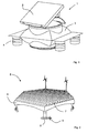
- Fig. 1 shows a floating photovoltaic element 1 with a photovoltaic module 2, which is mounted on a floss-like float 3 with several floats 4 and, for example, from the WO-2010144955 is known.
- This element shown can be coupled with other such PV elements 1, so as to make a whole solar field.
- photovoltaic system 5 includes a floating platform 6, on which a plurality of rows 7 are mounted with photovoltaic modules.
- the entire platform 6 has several underwater swimmers 8 and can be rotated by means of underwater drives 9 about a central axis.
- the underwater floats 8 can be flooded controlled or filled with air to compensate for a different load distribution and to better stabilize the platform in rough seas. It is understood that this example. In the WO-2009000249 described construction is not suitable for winter conditions with frost formation.
- the buoyancy point AP sometimes called the center of gravity FP, above the center of gravity SP of the entire wind turbine 10.
- the center of gravity AP is thus the point at which the static buoyancy attacks.
- Such plants are, for example, from the WO-2009068712 (closest prior art) known and not the subject of the present invention.
- complex control devices 11 are required. These are not suitable for use in alpine areas. It is understood that the present photovoltaic structure can also be combined with such a wind turbine. In particular, the energy yield can be significantly increased by the inventive use of bifacial modules.
- This in Fig. 4 illustrated hybrid power plant 12 includes a floating in the reservoir 13 of a hydroelectric power plant 14 photovoltaic system 5. It is used by the PV plant the same power infrastructure of the hydroelectric power plant. Such an arrangement is already out of the EP-2299499 known. Unfortunately, the concrete allows Construction of this floating PV system 5 No use in an alpine environment.
- Fig. 5 and Fig. 6 each show a spatial view of and under an inventive photovoltaic structure 20.
- This structure preferably has a diameter of about 30 m.
- this structure is equipped with bifacial modules 21. 21 '.
- the construction used has in a particular embodiment, a mast 22 of about 1 m in diameter and can withstand extreme environmental conditions, such as ice pressure, swell, alluvial, wind or snow loads in a simple manner.
- the modules 21. 21 ' can thus easily adapt to the fluctuating water level 23 without losing their position over ground.
- the underwater swimmers also known as diving swimmers, are a few meters under water and carry the photovoltaic system.
- Fig. 7 and Fig. 8 show views of an inventive photovoltaic park 31 respectively with umbrella-shaped photovoltaic structures 24 respectively. with band-shaped photovoltaic structures 25.
- the advantages of the photovoltaic system according to the invention with photovoltaic modules, which are held above the water surface, are in particular also to be seen in the fact that the modules are air-washed and thus have on average lower module temperatures and thus achieve a higher efficiency.
- the reflection of the daylight and the direct sunlight on the lake surface with used. is called the albedo gain. With closed ice and snow-covered surface, this proportion increases further. Measurements in comparable situations show an albedo gain of 30-50%.
- the floating structures can be advantageously tracked one or two axes of the sun orbit to further increase the yield.
- the arrangement of the photovoltaic systems in the alpine area changes the relationship between summer and winter in favor of the winter share.
- the hybrid power plants according to the invention can also produce electricity under diffuse sky light and ideally supplement the storable current from hydropower.
- the interaction of the two energy production plants increases the security of supply.
- the performance of the hybrid power plants according to the invention can be more than doubled.
- the load curve of long-term consumption can be optimally supplied on nice days.
- the solar-generated electricity reduces the water consumption of the hybrid power plant so that the accumulated volume of water is available for days when the sun is low and for the night.
- the fact that the existing hydropower plants can be used without significant structural changes and their electrical feed infrastructure proves to be particularly advantageous.
- a model calculation using the example of a 11 km 2 reservoir in Switzerland shows surprising findings.
- a net cell area of only 1.7 km 2 is needed.
- a pilot plant at about 1600 m above sea level. and in a reservoir with a water level of more than 60 m and a 1 m thick ice cover in winter with an active module area of about 400 m 2 , about 60 to 90 MWh / a of electricity can be generated. This corresponds to a share of electricity production of 40% and more in the winter half-year.
- Photovoltaic modules in parallel operation and with their own inverters, 3-phase and with 380 V guided. These values can be significantly increased with the use according to the invention of bifacial modules.
- the supply of the generated electricity to the local network of the hydroelectric power plant is bundled via an underwater cable. Swiss reservoirs are normally filled and emptied 2 to 5 times a year.
Landscapes
- Engineering & Computer Science (AREA)
- Architecture (AREA)
- Civil Engineering (AREA)
- Structural Engineering (AREA)
- Chemical & Material Sciences (AREA)
- Combustion & Propulsion (AREA)
- Mechanical Engineering (AREA)
- Ocean & Marine Engineering (AREA)
- Photovoltaic Devices (AREA)
Applications Claiming Priority (1)
| Application Number | Priority Date | Filing Date | Title |
|---|---|---|---|
| CH01037/12A CH706737A2 (de) | 2012-07-04 | 2012-07-04 | Wintertaugliche Energiegewinnungsanlage, insbesondere schwimmende Photovoltaik-Anlage. |
Publications (2)
| Publication Number | Publication Date |
|---|---|
| EP2682338A2 true EP2682338A2 (fr) | 2014-01-08 |
| EP2682338A3 EP2682338A3 (fr) | 2018-02-21 |
Family
ID=48874744
Family Applications (1)
| Application Number | Title | Priority Date | Filing Date |
|---|---|---|---|
| EP13003383.0A Ceased EP2682338A3 (fr) | 2012-07-04 | 2013-07-04 | Installation de collecte d'énergie adaptée à l'hiver |
Country Status (2)
| Country | Link |
|---|---|
| EP (1) | EP2682338A3 (fr) |
| CH (1) | CH706737A2 (fr) |
Citations (7)
| Publication number | Priority date | Publication date | Assignee | Title |
|---|---|---|---|---|
| US4786795A (en) | 1985-03-29 | 1988-11-22 | Kyocera Corporation | Sun tracking device floating upon liquid surface |
| JPH0781669A (ja) | 1993-09-16 | 1995-03-28 | Zeniraito V:Kk | 灯浮標の係留装置 |
| US20050084418A1 (en) | 2003-10-20 | 2005-04-21 | Hill David E. | Freeze resistant buoy system |
| WO2009000249A2 (fr) | 2007-06-28 | 2008-12-31 | Peter Nowak | Dispositif de génération d'énergie et d'eau douce en mer |
| WO2009068712A1 (fr) | 2007-11-29 | 2009-06-04 | Acciona Energia, S.A. | Système marin de production d'énergie électrique et procédé d'installation |
| WO2010144955A1 (fr) | 2009-06-17 | 2010-12-23 | Water Innovations Power And Technology Holdings Pty Ltd | Générateurs solaires flottants |
| EP2299499A1 (fr) | 2009-09-17 | 2011-03-23 | TNC Consulting AG | Agencement photovoltaïque flottant |
Family Cites Families (4)
| Publication number | Priority date | Publication date | Assignee | Title |
|---|---|---|---|---|
| WO2010101468A1 (fr) * | 2009-03-02 | 2010-09-10 | Hans Gude Gudesen | Dispositif à multiples éléments |
| KR101938589B1 (ko) * | 2010-07-08 | 2019-01-15 | 아이티알이씨 비. 브이. | 반잠수식 선박 및 작업 방법 |
| JP5736133B2 (ja) * | 2010-07-23 | 2015-06-17 | ジャパンマリンユナイテッド株式会社 | 浮体構造物作業システム、作業船及び浮体構造物作業方法 |
| WO2014005626A1 (fr) * | 2012-07-03 | 2014-01-09 | Staubli, Kurath & Partner Ag | Module d'installation solaire flottant et installation solaire correspondante |
-
2012
- 2012-07-04 CH CH01037/12A patent/CH706737A2/de not_active Application Discontinuation
-
2013
- 2013-07-04 EP EP13003383.0A patent/EP2682338A3/fr not_active Ceased
Patent Citations (7)
| Publication number | Priority date | Publication date | Assignee | Title |
|---|---|---|---|---|
| US4786795A (en) | 1985-03-29 | 1988-11-22 | Kyocera Corporation | Sun tracking device floating upon liquid surface |
| JPH0781669A (ja) | 1993-09-16 | 1995-03-28 | Zeniraito V:Kk | 灯浮標の係留装置 |
| US20050084418A1 (en) | 2003-10-20 | 2005-04-21 | Hill David E. | Freeze resistant buoy system |
| WO2009000249A2 (fr) | 2007-06-28 | 2008-12-31 | Peter Nowak | Dispositif de génération d'énergie et d'eau douce en mer |
| WO2009068712A1 (fr) | 2007-11-29 | 2009-06-04 | Acciona Energia, S.A. | Système marin de production d'énergie électrique et procédé d'installation |
| WO2010144955A1 (fr) | 2009-06-17 | 2010-12-23 | Water Innovations Power And Technology Holdings Pty Ltd | Générateurs solaires flottants |
| EP2299499A1 (fr) | 2009-09-17 | 2011-03-23 | TNC Consulting AG | Agencement photovoltaïque flottant |
Also Published As
| Publication number | Publication date |
|---|---|
| EP2682338A3 (fr) | 2018-02-21 |
| CH706737A2 (de) | 2014-01-15 |
Similar Documents
| Publication | Publication Date | Title |
|---|---|---|
| EP2299499B1 (fr) | Agencement photovoltaïque flottant | |
| EP3019740B1 (fr) | Éolienne flottante à base flottante et procédé d'installation d'une éolienne flottante de ce type | |
| EP2776705B1 (fr) | Installation de stockage d'énergie par pompage | |
| DE19714512C2 (de) | Maritime Kraftwerksanlage mit Herstellungsprozeß zur Gewinnung, Speicherung und zum Verbrauch von regenerativer Energie | |
| WO2009000249A2 (fr) | Dispositif de génération d'énergie et d'eau douce en mer | |
| DE102009008211B4 (de) | Energiegewinnung aus Wellen oder Impulsen | |
| EP3253649A1 (fr) | Dispositif de plate-forme | |
| DE10055973A1 (de) | Verfahren und Vorrichtung zur bedarfsabhängigen Regelung der Ausgangsleistung eines küstennahen Hochsee-Kraftwerks | |
| DE102012110662A1 (de) | Pumpspeicher-Wasserkraftwerk und Energieerzeugungs- und Speichersystem mit einem solchen Kraftwerk | |
| WO2014005626A1 (fr) | Module d'installation solaire flottant et installation solaire correspondante | |
| DE102012021697A1 (de) | Tragsystem für die Stabilisierung von mindestens einem Mast | |
| EP4283016A1 (fr) | Module de génération de l'hydrogène, ainsi qu'installation dotée d'une pluralité de tels modules | |
| DE202008013954U1 (de) | Wasserkraftanlage mit Wasserrädern, Schwimmkörpern, automatischer Höhenregulierung, Kleinwindkraftanlagen und Photovoltaik | |
| DE102021108107A1 (de) | Photovoltaik-Einheit für Gewässer | |
| DE202008006347U1 (de) | Tragsystem für eine Photovoltaikanlage | |
| DE102012017707A1 (de) | Energieröhrenkraftwerk | |
| EP2682338A2 (fr) | Installation de collecte d'énergie adaptée à l'hiver | |
| DE10156184A1 (de) | Schwimmfähige Solarzellenanlage mit Sonnenstandausrichtung, Hinterlüftung und biologischer Klärstufe | |
| DE3300049A1 (de) | Windkreisel, ein windenergiekonverter mit vertikaler achse fuer alle groessen bis in den 100 mw-bereich | |
| DE202008010364U1 (de) | Modular erweiterbares Gebäude | |
| DE3049331A1 (de) | Solarkraftwerk auf der erde | |
| WO1987005078A1 (fr) | Dispositif pour exploiter l'energie de la houle de l'eau de surface, et centrale houlomotrice contenant au moins un tel dispositif | |
| DE102013019229B4 (de) | Gezeitengenerator | |
| DE102011109117A1 (de) | Wasserkraftwerk (ohne Mast) | |
| DE202010016041U1 (de) | Windkraftanlage und Windpark |
Legal Events
| Date | Code | Title | Description |
|---|---|---|---|
| PUAI | Public reference made under article 153(3) epc to a published international application that has entered the european phase |
Free format text: ORIGINAL CODE: 0009012 |
|
| AK | Designated contracting states |
Kind code of ref document: A2 Designated state(s): AL AT BE BG CH CY CZ DE DK EE ES FI FR GB GR HR HU IE IS IT LI LT LU LV MC MK MT NL NO PL PT RO RS SE SI SK SM TR |
|
| AX | Request for extension of the european patent |
Extension state: BA ME |
|
| PUAL | Search report despatched |
Free format text: ORIGINAL CODE: 0009013 |
|
| AK | Designated contracting states |
Kind code of ref document: A3 Designated state(s): AL AT BE BG CH CY CZ DE DK EE ES FI FR GB GR HR HU IE IS IT LI LT LU LV MC MK MT NL NO PL PT RO RS SE SI SK SM TR |
|
| AX | Request for extension of the european patent |
Extension state: BA ME |
|
| RIC1 | Information provided on ipc code assigned before grant |
Ipc: B63B 35/08 20060101AFI20180118BHEP Ipc: B63B 35/44 20060101ALI20180118BHEP |
|
| 17P | Request for examination filed |
Effective date: 20180816 |
|
| 17Q | First examination report despatched |
Effective date: 20181128 |
|
| STAA | Information on the status of an ep patent application or granted ep patent |
Free format text: STATUS: THE APPLICATION HAS BEEN REFUSED |
|
| 18R | Application refused |
Effective date: 20200208 |