EP2682509A2 - Banc d'étirage pour un métier à tisser - Google Patents
Banc d'étirage pour un métier à tisser Download PDFInfo
- Publication number
- EP2682509A2 EP2682509A2 EP13003034.9A EP13003034A EP2682509A2 EP 2682509 A2 EP2682509 A2 EP 2682509A2 EP 13003034 A EP13003034 A EP 13003034A EP 2682509 A2 EP2682509 A2 EP 2682509A2
- Authority
- EP
- European Patent Office
- Prior art keywords
- rollers
- pair
- drafting
- drawframe according
- roller
- Prior art date
- Legal status (The legal status is an assumption and is not a legal conclusion. Google has not performed a legal analysis and makes no representation as to the accuracy of the status listed.)
- Granted
Links
- 238000009987 spinning Methods 0.000 title claims description 10
- 239000000835 fiber Substances 0.000 claims abstract description 7
- 230000006835 compression Effects 0.000 claims description 26
- 238000007906 compression Methods 0.000 claims description 26
- 238000007599 discharging Methods 0.000 claims description 5
- 238000012545 processing Methods 0.000 claims description 2
- 238000005056 compaction Methods 0.000 abstract description 4
- 230000002093 peripheral effect Effects 0.000 abstract 2
- 238000007378 ring spinning Methods 0.000 description 18
- 239000004753 textile Substances 0.000 description 4
- 238000013461 design Methods 0.000 description 3
- 239000000463 material Substances 0.000 description 3
- 239000002657 fibrous material Substances 0.000 description 2
- 239000003063 flame retardant Substances 0.000 description 2
- NJPPVKZQTLUDBO-UHFFFAOYSA-N novaluron Chemical compound C1=C(Cl)C(OC(F)(F)C(OC(F)(F)F)F)=CC=C1NC(=O)NC(=O)C1=C(F)C=CC=C1F NJPPVKZQTLUDBO-UHFFFAOYSA-N 0.000 description 2
- 238000005299 abrasion Methods 0.000 description 1
- 239000000969 carrier Substances 0.000 description 1
- 238000004140 cleaning Methods 0.000 description 1
- 238000010276 construction Methods 0.000 description 1
- 230000001419 dependent effect Effects 0.000 description 1
- 238000009826 distribution Methods 0.000 description 1
- 238000007786 electrostatic charging Methods 0.000 description 1
- 238000002474 experimental method Methods 0.000 description 1
- 238000009434 installation Methods 0.000 description 1
- 238000004519 manufacturing process Methods 0.000 description 1
- 238000000034 method Methods 0.000 description 1
- 230000000284 resting effect Effects 0.000 description 1
- 238000003860 storage Methods 0.000 description 1
- 238000012549 training Methods 0.000 description 1
Images


Classifications
-
- D—TEXTILES; PAPER
- D01—NATURAL OR MAN-MADE THREADS OR FIBRES; SPINNING
- D01H—SPINNING OR TWISTING
- D01H5/00—Drafting machines or arrangements ; Threading of roving into drafting machine
- D01H5/18—Drafting machines or arrangements without fallers or like pinned bars
- D01H5/22—Drafting machines or arrangements without fallers or like pinned bars in which fibres are controlled by rollers only
-
- D—TEXTILES; PAPER
- D01—NATURAL OR MAN-MADE THREADS OR FIBRES; SPINNING
- D01H—SPINNING OR TWISTING
- D01H5/00—Drafting machines or arrangements ; Threading of roving into drafting machine
- D01H5/18—Drafting machines or arrangements without fallers or like pinned bars
- D01H5/70—Constructional features of drafting elements
- D01H5/72—Fibre-condensing guides
Definitions
- the invention relates to a drafting system for a spinning machine according to the preamble of claim 1.
- Draw frames in various embodiments are known in connection with spinning machines, for example ring spinning machines, and are described in detail in numerous patent applications.
- Such drafting systems differ, for example, in terms of the number of pairs of rollers and / or in relation to the structural design of the pendulum carrier, which receive the top rollers. Also with regard to the exact training or the equipment of the different pairs of rollers considerable differences are sometimes known.
- the lower rollers are formed as machine-length components, which are composed of a plurality of roller segments.
- These machine-length lower rollers are usually driven by a strong, machine end side arranged in a drive frame of the textile machine drafting motor, which ensures via an intermediate reduction gear that rotate the input, the center and output lower rollers at different speeds and thereby distort the submitted fiber material properly ,
- the middle roller pair is equipped with so-called drafting straps. That is, in these modern drafting systems, both the middle upper roll and the lower middle roll each have such a delay strip, which secures the sliver to be distorted in the region of the so-called main drafting zone.
- a modern Riemchenstrecktechnik, in particular for warping of fire-retardant and heat-resistant yarn is for example in the US 7, 937, 924 B2 described.
- the input sub-roller is mounted on a carriage which is defined slidably mounted on a punch so that the default range of the so-called default zone is adjustable.
- both the middle lower roller, and the middle upper roller are stored, as usual in Riemchenstreckwerken, each equipped with a delay straps.
- the invention has for its object to provide a drafting system for a ring spinning machine, which is designed so that an existing filament template material can be processed reliably and quickly. That is, on the drafting system according to the invention, for example, fire-retardant and heat-resistant filaments should be able to be processed so that they can be spun on a downstream ring spinning device to a fiber material from which later garments can be made, which provide a comfortable wearing behavior.
- a compacting device In the conveying direction behind the pair of output rollers, a compacting device is further installed, which then ensures bundling of the resulting through the tearing open filament strand and thus ensures that this filament strand are spun by the spindle of a workstation of a spinning machine, preferably by a ring spinning spindle to a yarn can be further processed in subsequent work steps.
- a device for discharging electrostatic charges is connected to the drafting system (Anspr.2).
- the top rollers are each provided with a cover having a hardness of 60 to 90 Shore, that is, 60 to 70 Shore for the top rollers and 80 to 90 Shore for the input and middle top rollers.
- a cover having a hardness of 60 to 90 Shore allows the use of pendulum carriers, which allow a high loading force of the top rollers. That is, it can be used a pendulum carrier in which a high clamping force is adjustable between the top rollers and the associated corrugated bottom rollers.
- the loading force of the input and center rollers is greater than 25 daN.
- the top rollers have a diameter of 40-60 mm and the bottom rollers have a diameter of 30-40 mm.
- roller diameters are optimal both in the upper and in the area of the lower roller. That is, as a lower rollers, structured shaft segments having a diameter of 38 mm, which are connected to a continuous, machine-end driven component, have proven to be very advantageous.
- the top rollers each mounted in a pendulum carrier preferably have a diameter of 50 mm, which has also proved to be very advantageous in combination with the above-described, structured bottom rollers with a diameter of 38 mm.
- the drafting device on a compression device which is connected to a vacuum source.
- the compacting device ensures that the separated filament strand is bundled in the region of a so-called compaction zone to form a structure, which can then be spun onto a thread on a ring spinning spindle.
- a circumferential perforated belt is used.
- This perforated belt comprises, for example, a driven lower roller and a guide housing, which is connected via a pneumatic line to the vacuum source.
- Such trained and working compression devices are not fundamentally new in connection with ring spinning machine drafting systems, but work very reliably and are also very advantageous for the purpose of the invention. That is, in a compacting device, as used in the drafting device according to the invention, a separate filament strand leaving the pair of outfeed rollers is still untwisted, that is, with filamentary pieces substantially parallel to each other, pneumatically in a so-called compression zone by a vacuum-pressurized transport - And compacting contacted.
- the pending in this transport and compression means Saugluftströmung ensures that the filament pieces are positioned in the transport direction and thus bundled and compacted into a fiber structure.
- the compacting device as described in claim 10 may also have a circumferential perforated hollow roller connected to a vacuum source.
- the filament pieces can be positioned in the transport direction and thus bundled and compacted into a fiber structure.
- the pair of input rollers and the center roller pair form a so-called Vorverzugsfeld in which there is a 1.8 to 2.5 times the predilection of the filaments. That is, the default value of the default is increased compared to the usual Langstapeln Vorverzugswert, resulting in a better distortion distribution between main and Vorverzugsfeld.
- Such a design has the particular advantage that the forces to be expended are placed more on the preliminary delay and thus the main delay is relieved.
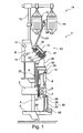
- the Fig.1 schematically shows a half-side cross-section of a ring spinning machine whose unillustrated side is mirror-inverted.
- the ring spinning machine 1 on a pedestal 2, from which vertical uprights 3 extend upward, which carry suction ducts 4, which are preferably rectangular in cross-section.
- bridge pieces 5 are fixed, which in turn support two extending in the machine longitudinal direction, parallel support tubes 6, where the bearing housing 7 are fixed for a variety of ring spindles.
- Fig.1 is shown schematically one of these ring spinning spindle, which is supported during the spinning operation with a spinning cop 8.
- punches 9 Resting on the suction channels 4 are so-called punches 9, which are each part of a drafting device 10 according to the invention.
- the punches 9 are also attached to two extending in the machine longitudinal support tubes 11.
- the ring spinning machine 1 further has vertically arranged support columns 13 for an original material gate 14.
- filament feed bobbins 15, whose original material is drawn off via a deflection bar 24 or the like, are suspended in the feedstock gate 14.
- the lifting devices for the ring rail 18, the balloon constriction rings 19 and the vertically displaceably mounted thread guide 20 are arranged.
- a bobbin changing device 33 On a boom 32 of the pedestal 2 of the ring spinning machine 1, a bobbin changing device 33 is further arranged, which consists essentially of a plurality of shear systems with scissor arms 34 and 35, a gripper bar 36 and arranged on the gripper bar 36 tube grippers 37.
- the scissors systems are actuated by means of a push / pull tube 38 which extends along the ring spinning machine 1.
- the Fig.2 shows a first advantageous embodiment of a drafting system 10 according to the invention in detail.
- Such drafting units 10 have, as is known, inter alia machine-length drivable lower rollers 21 u, 22u and 23u and upper rollers 21o, 22o and 23o, the rest during the spinning operation on the lower rollers 21 u, 22u and 23u and frictionally from these get picked up.
- the machine-length, drivable lower rollers 21u, 22u and 23u are mounted on slides 41 on punches 9, wherein the installation position of the lower rollers 21u, 22u and 23u, that is, the distance of the carriage 41 to each other, by means of corresponding bolts 42 or the like. Is adjustable.
- the machine-length lower rollers 21 u, 22u and 23u are generally each composed of a plurality of roller segment pieces with a diameter of between 30 and 40 mm, wherein the roller segment pieces are provided with a structuring 40 in the region of their working surfaces.
- such lower rollers 21 u, 22u and 23u are also, for example via a (not shown) reduction gear, connected to a machine end side arranged electromotive drive, that the speed of the lower roller 21u, 22u and 23u can be predetermined.
- both the warp value in a pre-drafting field 43 lying between the pair of input rollers 21 and the center roller pair 22, and the warp value in a main drafting field 44 are disposed between the intermediate roller pair 22 and the pair of output rollers 23 defined adjustable.
- a support 45 of the drafting system 10 is fixed to the punch 9 via a support rod 16, wherein on the support 45 via a rotation axis 46 each have a pendulum carrier 12 and a loading arm 17 of the drafting system 10 are stored.
- the pendulum carrier 12 is limited movable attached to the axis of rotation 46 and can by means of the load arm 17 in three possible positions a) "loaded", b) “relieved” and c) "folded” positioned.
- pendulum carrier 12 On pendulum carrier 12 are also, as known, mounted on corresponding (not shown) retaining elements in a paired arrangement, the top rollers 21o, 22o and 23o of the drafting system 10.
- the loading force that is, the force with which the upper rollers 21o to 23o rest on their associated lower rollers 21u to 23u, by the construction of the pendulum carrier 12 (spring-loaded instead of pneumatically tensioned top rollers) and the adjustable pressure force of the top rollers can be predetermined and is for the Output top rollers of the pendulum carrier 12 greater than 35 daN and set for the input and middle top rollers 21o and 22o to 25 daN
- the upper rollers 21o, 22o and 23o preferably each have a diameter between 40 and 60 mm and are provided with a relatively abrasion resistant cover 30, whose hardness is between 60 to 70 Shore for the top rollers and 80 to 90 Shore for the input and middle top rollers ,
- the drafting arrangement 10 also has a compacting device 28 for bundling separated and drawn filaments 27 and a device 29 for discharging the electrostatic charges generated during the stretching operation of the filaments 27.
- the means 29 for discharging electrostatic charges for example, connected to one of the punches 9 of the drafting system 10 and grounded Such means for discharging electrostatic charges are not fundamentally new in connection with textile machines and, for example in the DE 1 229 426 C described in detail using a route.
- compacting devices are basically known in connection with drafting systems of textile machines and described in detail in numerous patent applications in various embodiments.
- a mechanical compression device for a drafting system is shown while in the DE 199 32 099 A1 a compression device is described, which has a pressurizable, circumferential, roller as the compression element.
- a compression device 28 is installed, which is connected via a pneumatic line 50 to a vacuum source 52 and forms a compression zone 39, in the region of the separate filament strand 27 is pneumatically bundled.
- the punch 9 is provided with a bearing means 47 for a carriage 41, in which a preferably machine-length, machine-end driven
- Compression bottom roller 48 is mounted, which drives a compression top roller 49 frictionally via a rotatably mounted intermediate roller 48a and a drivable, perforated belt 51.
- the perforated belt 51 in this case comprises a guide housing 60 installed in the region of the bearing device 47, which is connected via a pneumatic line 50 to a vacuum source 52.
- an airflow 53 entering the vacuum-pressurized guide housing 60 via the circumferential, perforated belt 51 ensures that the separated filament pieces 27 are bundled substantially parallel in the region of the compression zone 39, so that they are arranged by means of a subsequently arranged Ring spinning spindle to a thread 26 are spinnable.
- the drafting system 10 may also have some mechanical guiding and compacting devices.
- the drafting system 10 may, for example, a so-called input compressor 56, an apron compressor 57 and a main field compressor 58, wherein in the region of the main drafting zone 44 also a guide rail 55 may be installed, which is so spaced from the pair of output rollers 23 that fibers in the cleaning process by a Wanderbläser Do not be jammed here and lead to thread breaks.
- a compression device 28 is installed following the pair of output rollers 23, which has a druckdruckaufeaufschlagbare, rotatably mounted compression top roller 59.
- the compression top roller 59 is connected via a pneumatic line 50 to a vacuum source 52 and processed during the spinning operation the separate (not shown here) filament strand 27 pneumatically.
- the punch 9 is equipped with a bearing device 47 in which a preferably machine-length, machine-end-driven compression bottom roller 48 is mounted, on which the compacting upper roller 59 druckallonsaufschlagbarbar.
- the compression top roller 59 is mounted for example on the pendulum carrier 12 and connected via a pneumatic line 50 to a vacuum source 52.
- the compaction top roller 59 is equipped with a perforation 31, which ensures that the separated filament pieces 27 are bundled in parallel, so that they can be spun on a subsequently arranged ring spinning spindle to form a thread.
Landscapes
- Engineering & Computer Science (AREA)
- Mechanical Engineering (AREA)
- Textile Engineering (AREA)
- Spinning Or Twisting Of Yarns (AREA)
- Preliminary Treatment Of Fibers (AREA)
Applications Claiming Priority (1)
| Application Number | Priority Date | Filing Date | Title |
|---|---|---|---|
| DE201210013574 DE102012013574A1 (de) | 2012-07-06 | 2012-07-06 | Streckwerk für eine Spinnmaschine |
Related Parent Applications (1)
| Application Number | Title | Priority Date | Filing Date |
|---|---|---|---|
| DE102012013574 Previously-Filed-Application | 2012-07-06 |
Publications (3)
| Publication Number | Publication Date |
|---|---|
| EP2682509A2 true EP2682509A2 (fr) | 2014-01-08 |
| EP2682509A3 EP2682509A3 (fr) | 2015-05-06 |
| EP2682509B1 EP2682509B1 (fr) | 2017-02-01 |
Family
ID=48669745
Family Applications (1)
| Application Number | Title | Priority Date | Filing Date |
|---|---|---|---|
| EP13003034.9A Not-in-force EP2682509B1 (fr) | 2012-07-06 | 2013-06-13 | Banc d'étirage pour un métier à tisser |
Country Status (4)
| Country | Link |
|---|---|
| EP (1) | EP2682509B1 (fr) |
| CN (1) | CN103526352A (fr) |
| DE (1) | DE102012013574A1 (fr) |
| ES (1) | ES2614476T3 (fr) |
Cited By (1)
| Publication number | Priority date | Publication date | Assignee | Title |
|---|---|---|---|---|
| CH714445A1 (de) * | 2017-12-15 | 2019-06-28 | Rieter Ag Maschf | Streckwerk für eine Spinnmaschine mit einer Verdichtungsvorrichtung. |
Families Citing this family (4)
| Publication number | Priority date | Publication date | Assignee | Title |
|---|---|---|---|---|
| DE102015014421A1 (de) * | 2015-10-22 | 2017-04-27 | Saurer Germany Gmbh & Co. Kg | Streckwerk und Lager für eine Welle eines Streckwerkes |
| CN108589022B (zh) * | 2018-07-02 | 2023-12-05 | 海安国洋机械科技有限公司 | 金属纤维拉断喷射装置 |
| CN110067059B (zh) * | 2019-05-22 | 2021-10-29 | 安徽翰联色纺股份有限公司 | 复合混纺纱的生产方法 |
| DE102020131090A1 (de) * | 2020-11-24 | 2022-05-25 | Maschinenfabrik Rieter Ag | Verfahren zur Durchführung eines automatischen Kannenwechselvorgangs an einer Spinnstelle einer Spinnmaschine sowie Spinnmaschine und verfahrbarer Kannenwechsler |
Citations (8)
| Publication number | Priority date | Publication date | Assignee | Title |
|---|---|---|---|---|
| DE1229426B (de) | 1960-02-05 | 1966-11-24 | Howa Machinery Ltd | Strecke zum Mischen von Fasern |
| DE2846065A1 (de) | 1978-10-23 | 1980-04-30 | Schlafhorst & Co W | Walzenstreckwerk |
| DE3016409A1 (de) | 1980-04-29 | 1981-11-05 | W. Schlafhorst & Co, 4050 Mönchengladbach | Walzenstreckwerk mit einer faserfuehrungsvorrichtung im hauptverzugsfeld |
| DE3128870A1 (de) | 1981-07-22 | 1983-02-10 | Fritjof Dipl.-Ing. Dr.-Ing. 6233 Kelkheim Maag | Streckwerk fuer das verziehen von spinnfaserbaendern |
| DE19932099A1 (de) | 1999-07-09 | 2001-01-11 | Rieter Ag Maschf | Spinnmaschine mit Verdichtungseinrichtung getrennt vom Streckwerk |
| DE10008610A1 (de) | 2000-02-24 | 2001-08-30 | Zinser Textilmaschinen Gmbh | Streckwerk für eine Spinnereimaschine |
| US7937924B2 (en) | 2005-11-16 | 2011-05-10 | Lorica International, Inc. | Fire retardant compositions and methods and apparatuses for making the same |
| DE102010054850A1 (de) | 2009-12-28 | 2011-06-30 | Rotorcraft Ag | Mehrteilige Verdichtereinrichtung zum Verdichten eines Faserbandes und Spinnereimaschine mit einer solchen Verdichtereinrichtung |
Family Cites Families (15)
| Publication number | Priority date | Publication date | Assignee | Title |
|---|---|---|---|---|
| GB424830A (en) * | 1933-05-22 | 1935-02-22 | British Celanese | Improvements in the manufacture of yarns containing staple fibre from continuous filaments |
| US2077320A (en) * | 1933-09-05 | 1937-04-13 | Celanese Corp | Manufacture of staple fiber yarns from continuous filaments |
| GB484192A (en) * | 1936-07-31 | 1938-05-02 | William Pool | Improvements in and relating to the conversion of continuous filaments into staple fibres |
| CH242571A (de) * | 1943-11-05 | 1946-05-31 | Onderzoekings Inst Res | Verfahren und Vorrichtung zur Herstellung von Zellwollgarnen durch Zerreissen von endlos gesponnenen Bündeln Kunstseidefäden und unmittelbar anschliessendes Zusammendrehen der zerrissenen Fadenstücke. |
| CH256210A (de) * | 1947-06-20 | 1948-08-15 | Rieter Joh Jacob & Cie Ag | Verfahren zur Herstellung eines aus kurzen Fasern bestehenden Garnes und Einrichtung zur Ausführung des Verfahrens. |
| FR1114964A (fr) * | 1954-10-28 | 1956-04-18 | Const Mecaniques De Stains Soc | Méthode et dispositif pour la fabrication de filés mixtes |
| GB1524145A (en) * | 1976-08-05 | 1978-09-06 | Dayco Corp | Textile cot assembly |
| DE19824078C2 (de) * | 1998-05-29 | 2001-05-31 | Zinser Textilmaschinen Gmbh | Verfahren beim Herstellen von verdichtetem Garn und Einrichtung hierfür |
| EP1205587A3 (fr) * | 2000-11-10 | 2002-12-11 | Maschinenfabrik Rieter Ag | Procédé et dispositif pour filer un fil en filaments déchirables |
| DE10214339A1 (de) * | 2002-03-28 | 2003-10-16 | Rieter Ingolstadt Spinnerei | Streckwerk für eine Spinnereimaschine |
| DE10317430B4 (de) * | 2003-04-15 | 2011-05-12 | Rieter Ingolstadt Gmbh | Textilmaschine mit einem Streckwerk |
| DE102004052177B4 (de) * | 2004-10-27 | 2013-10-31 | Rieter Ingolstadt Gmbh | Spinnereivorbereitungsmaschine sowie Gehäuse für ein Streckwerk einer Spinnereivorbereitungsmaschine |
| CN101092766A (zh) * | 2006-06-19 | 2007-12-26 | 天津宏大纺织机械有限公司 | 粗纱机的牵伸装置及控制方法 |
| DE102007039522B4 (de) * | 2007-08-21 | 2019-10-02 | Trützschler GmbH & Co Kommanditgesellschaft | Vorrichtung an einem Streckwerk einer Strecke für Textilfaserbänder |
| DE202007013020U1 (de) * | 2007-09-17 | 2007-11-22 | Sefar Ag | Siebriemchen für ein Streckwerk einer Spinnmaschine sowie Streckvorrichtung mit einem Siebriemchen |
-
2012
- 2012-07-06 DE DE201210013574 patent/DE102012013574A1/de not_active Withdrawn
-
2013
- 2013-06-13 EP EP13003034.9A patent/EP2682509B1/fr not_active Not-in-force
- 2013-06-13 ES ES13003034.9T patent/ES2614476T3/es active Active
- 2013-07-03 CN CN201310350247.1A patent/CN103526352A/zh active Pending
Patent Citations (8)
| Publication number | Priority date | Publication date | Assignee | Title |
|---|---|---|---|---|
| DE1229426B (de) | 1960-02-05 | 1966-11-24 | Howa Machinery Ltd | Strecke zum Mischen von Fasern |
| DE2846065A1 (de) | 1978-10-23 | 1980-04-30 | Schlafhorst & Co W | Walzenstreckwerk |
| DE3016409A1 (de) | 1980-04-29 | 1981-11-05 | W. Schlafhorst & Co, 4050 Mönchengladbach | Walzenstreckwerk mit einer faserfuehrungsvorrichtung im hauptverzugsfeld |
| DE3128870A1 (de) | 1981-07-22 | 1983-02-10 | Fritjof Dipl.-Ing. Dr.-Ing. 6233 Kelkheim Maag | Streckwerk fuer das verziehen von spinnfaserbaendern |
| DE19932099A1 (de) | 1999-07-09 | 2001-01-11 | Rieter Ag Maschf | Spinnmaschine mit Verdichtungseinrichtung getrennt vom Streckwerk |
| DE10008610A1 (de) | 2000-02-24 | 2001-08-30 | Zinser Textilmaschinen Gmbh | Streckwerk für eine Spinnereimaschine |
| US7937924B2 (en) | 2005-11-16 | 2011-05-10 | Lorica International, Inc. | Fire retardant compositions and methods and apparatuses for making the same |
| DE102010054850A1 (de) | 2009-12-28 | 2011-06-30 | Rotorcraft Ag | Mehrteilige Verdichtereinrichtung zum Verdichten eines Faserbandes und Spinnereimaschine mit einer solchen Verdichtereinrichtung |
Cited By (1)
| Publication number | Priority date | Publication date | Assignee | Title |
|---|---|---|---|---|
| CH714445A1 (de) * | 2017-12-15 | 2019-06-28 | Rieter Ag Maschf | Streckwerk für eine Spinnmaschine mit einer Verdichtungsvorrichtung. |
Also Published As
| Publication number | Publication date |
|---|---|
| EP2682509B1 (fr) | 2017-02-01 |
| EP2682509A3 (fr) | 2015-05-06 |
| ES2614476T3 (es) | 2017-05-31 |
| CN103526352A (zh) | 2014-01-22 |
| DE102012013574A1 (de) | 2014-05-22 |
Similar Documents
| Publication | Publication Date | Title |
|---|---|---|
| DE19708410B4 (de) | Streckwerk für Spinnmaschinen mit einer Faserbündelungszone | |
| DE19815053B4 (de) | Verfahren zum Herstellen eines Scheinzwirnes und Spinnmaschine hierfür | |
| DE102005036485A1 (de) | Offenend-Rotorspinnmaschine | |
| EP2682509B1 (fr) | Banc d'étirage pour un métier à tisser | |
| EP2966201A2 (fr) | Métier à tisser à rotor semi-automatique à extrémité ouverte | |
| EP2740821B1 (fr) | Dispositif de filage pneumatique | |
| DE10236450A1 (de) | Spinnmaschine mit einem Mehrstufen-Verdichtungs-Streckwerk | |
| DE68925017T2 (de) | Automatisches Ansetzen eines Faserbandes in einer Textilmaschine. | |
| DE3926227C2 (fr) | ||
| DE3611050A1 (de) | Verfahren und vorrichtung an einem spinnaggregat | |
| EP1573098B1 (fr) | Dispositif pour fabriquer une fibre filee | |
| EP2980284B1 (fr) | Procede de fabrication d'un fil produit par jet d'air | |
| EP0924323B2 (fr) | Dispositif d'étirage pour des métiers à filer | |
| DE4123205C2 (de) | Faserbandtrennung an Spinnereivorbereitungsmaschinen | |
| EP3149229B1 (fr) | Machine de préparation de filature | |
| EP3724383A1 (fr) | Dispositif d'étirage pour un métier à filer comprenant un dispositif de compactage | |
| DE2541572C3 (de) | Vorrichtung zum Aufwickeln eines Vorgarnes oder Faserbandes zu einem Wickelkörper auf einem Spulenröhrchen | |
| EP3149230A1 (fr) | Machine de préparation de filature | |
| DE102007023488B4 (de) | Luftspinnmaschine | |
| EP3140233B1 (fr) | Machine textile pour la production d'une meche et procede de demarrage d'une telle machine pour produire une meche | |
| DE19516414A1 (de) | Spinnmaschine mit Fadenführer am Streckwerk | |
| EP4567170A1 (fr) | Dispositif compresseur | |
| EP3580379A1 (fr) | Procédé et installation de traitement de fibres | |
| DE4037834A1 (de) | Vorrichtung zum pneumatischen falschdrallspinnen | |
| DE4140669A1 (de) | Spinnmaschine |
Legal Events
| Date | Code | Title | Description |
|---|---|---|---|
| PUAI | Public reference made under article 153(3) epc to a published international application that has entered the european phase |
Free format text: ORIGINAL CODE: 0009012 |
|
| AK | Designated contracting states |
Kind code of ref document: A2 Designated state(s): AL AT BE BG CH CY CZ DE DK EE ES FI FR GB GR HR HU IE IS IT LI LT LU LV MC MK MT NL NO PL PT RO RS SE SI SK SM TR |
|
| AX | Request for extension of the european patent |
Extension state: BA ME |
|
| PUAL | Search report despatched |
Free format text: ORIGINAL CODE: 0009013 |
|
| AK | Designated contracting states |
Kind code of ref document: A3 Designated state(s): AL AT BE BG CH CY CZ DE DK EE ES FI FR GB GR HR HU IE IS IT LI LT LU LV MC MK MT NL NO PL PT RO RS SE SI SK SM TR |
|
| AX | Request for extension of the european patent |
Extension state: BA ME |
|
| RIC1 | Information provided on ipc code assigned before grant |
Ipc: D01H 5/72 20060101ALI20150331BHEP Ipc: D01H 5/22 20060101AFI20150331BHEP |
|
| 17P | Request for examination filed |
Effective date: 20151106 |
|
| RBV | Designated contracting states (corrected) |
Designated state(s): AL AT BE BG CH CY CZ DE DK EE ES FI FR GB GR HR HU IE IS IT LI LT LU LV MC MK MT NL NO PL PT RO RS SE SI SK SM TR |
|
| 17Q | First examination report despatched |
Effective date: 20151223 |
|
| GRAP | Despatch of communication of intention to grant a patent |
Free format text: ORIGINAL CODE: EPIDOSNIGR1 |
|
| INTG | Intention to grant announced |
Effective date: 20160816 |
|
| GRAJ | Information related to disapproval of communication of intention to grant by the applicant or resumption of examination proceedings by the epo deleted |
Free format text: ORIGINAL CODE: EPIDOSDIGR1 |
|
| GRAP | Despatch of communication of intention to grant a patent |
Free format text: ORIGINAL CODE: EPIDOSNIGR1 |
|
| GRAS | Grant fee paid |
Free format text: ORIGINAL CODE: EPIDOSNIGR3 |
|
| INTC | Intention to grant announced (deleted) | ||
| GRAA | (expected) grant |
Free format text: ORIGINAL CODE: 0009210 |
|
| INTG | Intention to grant announced |
Effective date: 20161206 |
|
| AK | Designated contracting states |
Kind code of ref document: B1 Designated state(s): AL AT BE BG CH CY CZ DE DK EE ES FI FR GB GR HR HU IE IS IT LI LT LU LV MC MK MT NL NO PL PT RO RS SE SI SK SM TR |
|
| REG | Reference to a national code |
Ref country code: GB Ref legal event code: FG4D Free format text: NOT ENGLISH |
|
| REG | Reference to a national code |
Ref country code: CH Ref legal event code: EP Ref country code: AT Ref legal event code: REF Ref document number: 865692 Country of ref document: AT Kind code of ref document: T Effective date: 20170215 |
|
| REG | Reference to a national code |
Ref country code: IE Ref legal event code: FG4D Free format text: LANGUAGE OF EP DOCUMENT: GERMAN |
|
| REG | Reference to a national code |
Ref country code: DE Ref legal event code: R096 Ref document number: 502013006193 Country of ref document: DE |
|
| REG | Reference to a national code |
Ref country code: ES Ref legal event code: FG2A Ref document number: 2614476 Country of ref document: ES Kind code of ref document: T3 Effective date: 20170531 |
|
| REG | Reference to a national code |
Ref country code: NL Ref legal event code: MP Effective date: 20170201 |
|
| REG | Reference to a national code |
Ref country code: LT Ref legal event code: MG4D |
|
| PG25 | Lapsed in a contracting state [announced via postgrant information from national office to epo] |
Ref country code: IS Free format text: LAPSE BECAUSE OF FAILURE TO SUBMIT A TRANSLATION OF THE DESCRIPTION OR TO PAY THE FEE WITHIN THE PRESCRIBED TIME-LIMIT Effective date: 20170601 Ref country code: LT Free format text: LAPSE BECAUSE OF FAILURE TO SUBMIT A TRANSLATION OF THE DESCRIPTION OR TO PAY THE FEE WITHIN THE PRESCRIBED TIME-LIMIT Effective date: 20170201 Ref country code: FI Free format text: LAPSE BECAUSE OF FAILURE TO SUBMIT A TRANSLATION OF THE DESCRIPTION OR TO PAY THE FEE WITHIN THE PRESCRIBED TIME-LIMIT Effective date: 20170201 Ref country code: NO Free format text: LAPSE BECAUSE OF FAILURE TO SUBMIT A TRANSLATION OF THE DESCRIPTION OR TO PAY THE FEE WITHIN THE PRESCRIBED TIME-LIMIT Effective date: 20170501 Ref country code: HR Free format text: LAPSE BECAUSE OF FAILURE TO SUBMIT A TRANSLATION OF THE DESCRIPTION OR TO PAY THE FEE WITHIN THE PRESCRIBED TIME-LIMIT Effective date: 20170201 Ref country code: GR Free format text: LAPSE BECAUSE OF FAILURE TO SUBMIT A TRANSLATION OF THE DESCRIPTION OR TO PAY THE FEE WITHIN THE PRESCRIBED TIME-LIMIT Effective date: 20170502 |
|
| PGFP | Annual fee paid to national office [announced via postgrant information from national office to epo] |
Ref country code: CZ Payment date: 20170522 Year of fee payment: 5 |
|
| PG25 | Lapsed in a contracting state [announced via postgrant information from national office to epo] |
Ref country code: LV Free format text: LAPSE BECAUSE OF FAILURE TO SUBMIT A TRANSLATION OF THE DESCRIPTION OR TO PAY THE FEE WITHIN THE PRESCRIBED TIME-LIMIT Effective date: 20170201 Ref country code: RS Free format text: LAPSE BECAUSE OF FAILURE TO SUBMIT A TRANSLATION OF THE DESCRIPTION OR TO PAY THE FEE WITHIN THE PRESCRIBED TIME-LIMIT Effective date: 20170201 Ref country code: NL Free format text: LAPSE BECAUSE OF FAILURE TO SUBMIT A TRANSLATION OF THE DESCRIPTION OR TO PAY THE FEE WITHIN THE PRESCRIBED TIME-LIMIT Effective date: 20170201 Ref country code: PL Free format text: LAPSE BECAUSE OF FAILURE TO SUBMIT A TRANSLATION OF THE DESCRIPTION OR TO PAY THE FEE WITHIN THE PRESCRIBED TIME-LIMIT Effective date: 20170201 Ref country code: BG Free format text: LAPSE BECAUSE OF FAILURE TO SUBMIT A TRANSLATION OF THE DESCRIPTION OR TO PAY THE FEE WITHIN THE PRESCRIBED TIME-LIMIT Effective date: 20170501 Ref country code: SE Free format text: LAPSE BECAUSE OF FAILURE TO SUBMIT A TRANSLATION OF THE DESCRIPTION OR TO PAY THE FEE WITHIN THE PRESCRIBED TIME-LIMIT Effective date: 20170201 Ref country code: PT Free format text: LAPSE BECAUSE OF FAILURE TO SUBMIT A TRANSLATION OF THE DESCRIPTION OR TO PAY THE FEE WITHIN THE PRESCRIBED TIME-LIMIT Effective date: 20170601 |
|
| PGFP | Annual fee paid to national office [announced via postgrant information from national office to epo] |
Ref country code: TR Payment date: 20170606 Year of fee payment: 5 |
|
| PG25 | Lapsed in a contracting state [announced via postgrant information from national office to epo] |
Ref country code: RO Free format text: LAPSE BECAUSE OF FAILURE TO SUBMIT A TRANSLATION OF THE DESCRIPTION OR TO PAY THE FEE WITHIN THE PRESCRIBED TIME-LIMIT Effective date: 20170201 Ref country code: EE Free format text: LAPSE BECAUSE OF FAILURE TO SUBMIT A TRANSLATION OF THE DESCRIPTION OR TO PAY THE FEE WITHIN THE PRESCRIBED TIME-LIMIT Effective date: 20170201 Ref country code: SK Free format text: LAPSE BECAUSE OF FAILURE TO SUBMIT A TRANSLATION OF THE DESCRIPTION OR TO PAY THE FEE WITHIN THE PRESCRIBED TIME-LIMIT Effective date: 20170201 |
|
| REG | Reference to a national code |
Ref country code: DE Ref legal event code: R097 Ref document number: 502013006193 Country of ref document: DE |
|
| PG25 | Lapsed in a contracting state [announced via postgrant information from national office to epo] |
Ref country code: DK Free format text: LAPSE BECAUSE OF FAILURE TO SUBMIT A TRANSLATION OF THE DESCRIPTION OR TO PAY THE FEE WITHIN THE PRESCRIBED TIME-LIMIT Effective date: 20170201 Ref country code: SM Free format text: LAPSE BECAUSE OF FAILURE TO SUBMIT A TRANSLATION OF THE DESCRIPTION OR TO PAY THE FEE WITHIN THE PRESCRIBED TIME-LIMIT Effective date: 20170201 |
|
| PLBE | No opposition filed within time limit |
Free format text: ORIGINAL CODE: 0009261 |
|
| STAA | Information on the status of an ep patent application or granted ep patent |
Free format text: STATUS: NO OPPOSITION FILED WITHIN TIME LIMIT |
|
| REG | Reference to a national code |
Ref country code: DE Ref legal event code: R119 Ref document number: 502013006193 Country of ref document: DE |
|
| 26N | No opposition filed |
Effective date: 20171103 |
|
| PG25 | Lapsed in a contracting state [announced via postgrant information from national office to epo] |
Ref country code: MC Free format text: LAPSE BECAUSE OF FAILURE TO SUBMIT A TRANSLATION OF THE DESCRIPTION OR TO PAY THE FEE WITHIN THE PRESCRIBED TIME-LIMIT Effective date: 20170201 |
|
| REG | Reference to a national code |
Ref country code: CH Ref legal event code: PL |
|
| GBPC | Gb: european patent ceased through non-payment of renewal fee |
Effective date: 20170613 |
|
| PG25 | Lapsed in a contracting state [announced via postgrant information from national office to epo] |
Ref country code: SI Free format text: LAPSE BECAUSE OF FAILURE TO SUBMIT A TRANSLATION OF THE DESCRIPTION OR TO PAY THE FEE WITHIN THE PRESCRIBED TIME-LIMIT Effective date: 20170201 |
|
| REG | Reference to a national code |
Ref country code: IE Ref legal event code: MM4A |
|
| REG | Reference to a national code |
Ref country code: FR Ref legal event code: ST Effective date: 20180228 |
|
| PG25 | Lapsed in a contracting state [announced via postgrant information from national office to epo] |
Ref country code: LI Free format text: LAPSE BECAUSE OF NON-PAYMENT OF DUE FEES Effective date: 20170630 Ref country code: IE Free format text: LAPSE BECAUSE OF NON-PAYMENT OF DUE FEES Effective date: 20170613 Ref country code: DE Free format text: LAPSE BECAUSE OF NON-PAYMENT OF DUE FEES Effective date: 20180103 Ref country code: GB Free format text: LAPSE BECAUSE OF NON-PAYMENT OF DUE FEES Effective date: 20170613 Ref country code: LU Free format text: LAPSE BECAUSE OF NON-PAYMENT OF DUE FEES Effective date: 20170613 Ref country code: CH Free format text: LAPSE BECAUSE OF NON-PAYMENT OF DUE FEES Effective date: 20170630 |
|
| PG25 | Lapsed in a contracting state [announced via postgrant information from national office to epo] |
Ref country code: FR Free format text: LAPSE BECAUSE OF NON-PAYMENT OF DUE FEES Effective date: 20170630 Ref country code: IT Free format text: LAPSE BECAUSE OF NON-PAYMENT OF DUE FEES Effective date: 20170613 |
|
| REG | Reference to a national code |
Ref country code: BE Ref legal event code: MM Effective date: 20170630 |
|
| PG25 | Lapsed in a contracting state [announced via postgrant information from national office to epo] |
Ref country code: BE Free format text: LAPSE BECAUSE OF NON-PAYMENT OF DUE FEES Effective date: 20170630 |
|
| PG25 | Lapsed in a contracting state [announced via postgrant information from national office to epo] |
Ref country code: MT Free format text: LAPSE BECAUSE OF FAILURE TO SUBMIT A TRANSLATION OF THE DESCRIPTION OR TO PAY THE FEE WITHIN THE PRESCRIBED TIME-LIMIT Effective date: 20170201 |
|
| REG | Reference to a national code |
Ref country code: ES Ref legal event code: FD2A Effective date: 20181017 |
|
| PG25 | Lapsed in a contracting state [announced via postgrant information from national office to epo] |
Ref country code: CZ Free format text: LAPSE BECAUSE OF NON-PAYMENT OF DUE FEES Effective date: 20180613 |
|
| PG25 | Lapsed in a contracting state [announced via postgrant information from national office to epo] |
Ref country code: ES Free format text: LAPSE BECAUSE OF NON-PAYMENT OF DUE FEES Effective date: 20170614 |
|
| PG25 | Lapsed in a contracting state [announced via postgrant information from national office to epo] |
Ref country code: HU Free format text: LAPSE BECAUSE OF FAILURE TO SUBMIT A TRANSLATION OF THE DESCRIPTION OR TO PAY THE FEE WITHIN THE PRESCRIBED TIME-LIMIT; INVALID AB INITIO Effective date: 20130613 |
|
| REG | Reference to a national code |
Ref country code: AT Ref legal event code: MM01 Ref document number: 865692 Country of ref document: AT Kind code of ref document: T Effective date: 20180613 |
|
| PG25 | Lapsed in a contracting state [announced via postgrant information from national office to epo] |
Ref country code: CY Free format text: LAPSE BECAUSE OF NON-PAYMENT OF DUE FEES Effective date: 20170201 |
|
| PG25 | Lapsed in a contracting state [announced via postgrant information from national office to epo] |
Ref country code: MK Free format text: LAPSE BECAUSE OF FAILURE TO SUBMIT A TRANSLATION OF THE DESCRIPTION OR TO PAY THE FEE WITHIN THE PRESCRIBED TIME-LIMIT Effective date: 20170201 |
|
| PG25 | Lapsed in a contracting state [announced via postgrant information from national office to epo] |
Ref country code: AT Free format text: LAPSE BECAUSE OF NON-PAYMENT OF DUE FEES Effective date: 20180613 |
|
| PG25 | Lapsed in a contracting state [announced via postgrant information from national office to epo] |
Ref country code: AL Free format text: LAPSE BECAUSE OF FAILURE TO SUBMIT A TRANSLATION OF THE DESCRIPTION OR TO PAY THE FEE WITHIN THE PRESCRIBED TIME-LIMIT Effective date: 20170201 |
|
| PG25 | Lapsed in a contracting state [announced via postgrant information from national office to epo] |
Ref country code: TR Free format text: LAPSE BECAUSE OF NON-PAYMENT OF DUE FEES Effective date: 20180613 |