EP2682512A2 - Waschmaschine - Google Patents
Waschmaschine Download PDFInfo
- Publication number
- EP2682512A2 EP2682512A2 EP13174876.6A EP13174876A EP2682512A2 EP 2682512 A2 EP2682512 A2 EP 2682512A2 EP 13174876 A EP13174876 A EP 13174876A EP 2682512 A2 EP2682512 A2 EP 2682512A2
- Authority
- EP
- European Patent Office
- Prior art keywords
- hinge
- arm
- door
- washing machine
- stopper
- Prior art date
- Legal status (The legal status is an assumption and is not a legal conclusion. Google has not performed a legal analysis and makes no representation as to the accuracy of the status listed.)
- Withdrawn
Links
Images


Classifications
-
- D—TEXTILES; PAPER
- D06—TREATMENT OF TEXTILES OR THE LIKE; LAUNDERING; FLEXIBLE MATERIALS NOT OTHERWISE PROVIDED FOR
- D06F—LAUNDERING, DRYING, IRONING, PRESSING OR FOLDING TEXTILE ARTICLES
- D06F37/00—Details specific to washing machines covered by groups D06F21/00 - D06F25/00
- D06F37/26—Casings; Tubs
- D06F37/28—Doors; Security means therefor
-
- D—TEXTILES; PAPER
- D06—TREATMENT OF TEXTILES OR THE LIKE; LAUNDERING; FLEXIBLE MATERIALS NOT OTHERWISE PROVIDED FOR
- D06F—LAUNDERING, DRYING, IRONING, PRESSING OR FOLDING TEXTILE ARTICLES
- D06F37/00—Details specific to washing machines covered by groups D06F21/00 - D06F25/00
- D06F37/02—Rotary receptacles, e.g. drums
- D06F37/04—Rotary receptacles, e.g. drums adapted for rotation or oscillation about a horizontal or inclined axis
- D06F37/10—Doors; Securing means therefor
-
- D—TEXTILES; PAPER
- D06—TREATMENT OF TEXTILES OR THE LIKE; LAUNDERING; FLEXIBLE MATERIALS NOT OTHERWISE PROVIDED FOR
- D06F—LAUNDERING, DRYING, IRONING, PRESSING OR FOLDING TEXTILE ARTICLES
- D06F37/00—Details specific to washing machines covered by groups D06F21/00 - D06F25/00
- D06F37/26—Casings; Tubs
-
- D—TEXTILES; PAPER
- D06—TREATMENT OF TEXTILES OR THE LIKE; LAUNDERING; FLEXIBLE MATERIALS NOT OTHERWISE PROVIDED FOR
- D06F—LAUNDERING, DRYING, IRONING, PRESSING OR FOLDING TEXTILE ARTICLES
- D06F39/00—Details of washing machines not specific to a single type of machines covered by groups D06F9/00 - D06F27/00
- D06F39/12—Casings; Tubs
- D06F39/14—Doors or covers; Securing means therefor
-
- E—FIXED CONSTRUCTIONS
- E05—LOCKS; KEYS; WINDOW OR DOOR FITTINGS; SAFES
- E05D—HINGES OR SUSPENSION DEVICES FOR DOORS, WINDOWS OR WINGS
- E05D11/00—Additional features or accessories of hinges
- E05D11/0054—Covers, e.g. for protection
-
- E—FIXED CONSTRUCTIONS
- E05—LOCKS; KEYS; WINDOW OR DOOR FITTINGS; SAFES
- E05D—HINGES OR SUSPENSION DEVICES FOR DOORS, WINDOWS OR WINGS
- E05D3/00—Hinges with pins
-
- E—FIXED CONSTRUCTIONS
- E05—LOCKS; KEYS; WINDOW OR DOOR FITTINGS; SAFES
- E05Y—INDEXING SCHEME ASSOCIATED WITH SUBCLASSES E05D AND E05F, RELATING TO CONSTRUCTION ELEMENTS, ELECTRIC CONTROL, POWER SUPPLY, POWER SIGNAL OR TRANSMISSION, USER INTERFACES, MOUNTING OR COUPLING, DETAILS, ACCESSORIES, AUXILIARY OPERATIONS NOT OTHERWISE PROVIDED FOR, APPLICATION THEREOF
- E05Y2900/00—Application of doors, windows, wings or fittings thereof
- E05Y2900/30—Application of doors, windows, wings or fittings thereof for domestic appliances
- E05Y2900/312—Application of doors, windows, wings or fittings thereof for domestic appliances for washing machines or laundry dryers
Definitions
- Embodiments relate to a combination structure of a door that opens/closes a laundry port of a washing machine.
- a drum washing machine as a machine that washes clothes using power generally includes a tub in which washing water is stored, a drum that is rotatably installed in the tub, and a driving motor for rotating the drum.
- a tub in which washing water is stored
- a drum that is rotatably installed in the tub
- a driving motor for rotating the drum.
- An opening through which laundry is put into or taken out, is formed in a front side of the drum washing machine, and a door that opens/closes the opening is rotatably coupled to the front side of the drum washing machine using a hinge member.
- the hinge member When a user opens/closes the door repeatedly for a long term during the usage of the drum washing machine, the hinge member may be damaged due to the weight of the door or shock applied when the door is opened/closed, Damage of the hinge member causes sagging of the door, which gives much inconvenience to the user in using the drum washing machine.
- a washing machine having an improved structure in which a door may be firmly supported not to sag even though the door is repeatedly opened/closed for a long term while a user uses the washing machine.
- a washing machine including: a main body; an opening formed in a front side of the main body; a door that opens/closes the opening; and a hinge member that allows the door to be rotatably coupled to the front side of the main body, wherein the hinge member includes: a hinge body coupled to the front side of the main body; at least one hinge arm that extends from the hinge body; and at least one stopper that protrudes from an outer side of the at least one hinge arm, wherein the door includes: a transparent member through which a user sees an inner side of a drum a holder member to which the transparent member is coupled and which has at least one accommodation groove in which at least a portion of the at least one hinge arm is accommodated; and a cover plate that covers the at least one accommodation groove to support the at least one hinge arm and has at least one protrusion that protrudes from an inner side of the cover plate toward the at least one hinge arm, and wherein when the door opens the opening, the at
- a first contact side may be provided at one end of the at least one protrusion
- a second contact side may be provided at one end of the at least one stopper and may contact the first contact side
- an angle between a direction that is perpendicular to the first contact side and the second contact side and a direction in which the cover plate covers the at least one accommodation groove may be greater than 0° and less than 90°.
- the cover plate may include at least one protrusion formation hole for forming the at least one protrusion.
- the hinge member may be manufactured using injection molding, and a material for the hinge member may be engineering plastic including glass fiber.
- the at least one hinge arm may include a first arm that extends from the hinge body, a second arm that slantingly extends from one end of the first arm, and a hinge shaft that extends from the second arm in a vertical direction, and a distance from a rotational center of the hinge shaft to one end of the at least one stopper may be longer than a distance from the rotational center of the hinge shaft to one end of the at least one protrusion.
- a washing machine including: a main body; a drum that is rotatably installed in the main body; a laundry port which is formed at a front side of the main body and through which laundry is put into the drum; a hinge plate including a hinge body coupled to the front side of the main body toward an outer side of the laundry port and at least one hinge arm that extends from the hinge body; a door that is rotatably coupled to the at least one hinge arm so as to open/close the laundry port and includes an accommodation part accommodating at least a portion of the at least one hinge arm; and a stopper that protrudes from an outer side of the at least one hinge arm and is in contact with at least a portion of the accommodation part so as to limit rotation of the door when the door opens the laundry port.
- the accommodation part may include a rotation limitation protrusion that protrudes from an inner side of the accommodation part toward the at least one hinge arm, and the rotation limitation protrusion may be in contact with the stopper and may limit rotation of the door.
- the rotation limitation protrusion may pressurize the stopper in a direction toward the drum.
- the door may include: a transparent member through which a user sees an inner side of the drum; a holder member to which the transparent member is coupled and which has an accommodation groove in which at least a portion of the at least one hinge arm is accommodated, the accommodating groove being formed in one side of the holder member; and a covey plate that covers the accommodation groove and constitutes the accommodation part together with the accommodation groove.
- the hinge arm may include a first arm that extends from the hinge body, a second arm that slantingly extends from one end of the first arm, and a hinge shaft that extends from the second arm in a vertical direction and is a rotational center of the door, and the accommodation groove may include a first accommodation groove in which the second arm is accommodated and a second accommodation groove which crosses the first accommodation groove and in which the hinge shaft is accommodated.
- the stopper may protrude from an outer side of the second arm, and the cover plate may include a rotation limitation protrusion that protrudes from an inner side of the cover plate toward the hinge arm, is in contact with the stopper and limits rotation of the door.
- An angle between a virtual, first straight line that connects a rotational center of the hinge shaft and one end of the stopper and a virtual, second straight line that connects the rotational center of the hinge shaft and one end of the second arm connected to the first arm may be equal to or greater than 90° and equal to or less than 180°.
- An angle between a direction in which the stopper pressurizes the rotation limitation protrusion and a direction in which the cover plate is coupled to the holder member, may be greater than 0° and less than 90°.
- the stopper and the second arm may be disposed at both sides of a virtual, third straight line based on the virtual, third straight line that is parallel to a rotational center of the drum and passes the rotational center of the hinge shaft in a state in which the door closes the laundry port.
- a first contact side may be provided at one end of the rotation limitation protrusion
- a second contact side may be provided at one end of the stopper, may contact the first contact side, and may pressurize the first contact side, and an angle between a direction that is parallel to the first contact side and the second contact side and a direction in which the cover plate is coupled to the holder member, may be greater than 0° and less than 90°.
- a distance from a rotational center of the at least one hinge arm to one end of the protrusion may be shorter than a distance from the rotational center of the hinge arm to one end of the stopper.
- a material for the hinge plate may be engineering plastic.
- the hinge plate may include glass fiber (GF) having a content of 60% or more.
- GF glass fiber
- a washing machine including a main body having an opening; a door that opens/closes the opening: and a hinge member rotatably coupling the door to the main body, wherein the hinge member includes a hinge body coupled to the main body; a hinge arm that extends from the hinge body; and a stopper that protrudes from an outer side of the hinge arm, wherein the door includes a transparent member through which a user sees an inner side of a drum; a holder member to which the transparent member is coupled and which has an accommodation groove in which at least a portion of the hinge arm is accommodated; and a cover plate that covers the accommodation groove to support the hinge arm and has a protrusion that protrudes from an inner side of the accommodation groove toward the hinge arm, and wherein when the door opens the opening, the stopper and the protrusion are in contact with each other so that rotation of the door is limited.
- FIG. 1 is a perspective view illustrating the exterior of a washing machine according to an embodiment.
- the washing machine includes a main body 10 that constitutes the exterior, a tub (not shown) which is disposed in the main body 10 and in which washing water is stored, and a drum 12 that is rotatably disposed in the tub (not shown) so as to wash laundry.
- a control panel assembly 14 is disposed at a front upper part of the main body 10 so that a user may control an operation of the washing machine.
- a laundry port 16 through which laundry may be put into the drum 12 is disposed at a front side of the main body 10, and a door 100 is installed at the front side of the main body 10 so as to open/close the laundry port 16.
- the door 100 is rotatably coupled to a hinge member 200 installed at the front side of the main body 10.
- FIG. 2 is an exploded view illustrating some elements of the door 100 in a state in which the door 100 closes the laundry port 16
- FIG. 3 is an exploded perspective view illustrating the door 100 of the washing machine
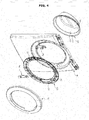
- FIG. 4 is an exploded perspective view illustrating a combination relationship between the door 100 and the hinge member 200 of the washing machine
- FIG. 5 is an exploded view illustrating a cover plate 140 in a state in which the door 100 and the hinge member 200 are coupled to each other
- FIG. 6 is an exploded perspective view illustrating the combination relationship between the door 100 and the hinge member 200
- FIG. 7 is a view illustrating FIG. 3 at a different angle.
- the door 100 includes a transparent member 110 through which the user may check an inner side of the drum 12, a holder member 120 to which the transparent member 110 is coupled and which has an accommodation groove 128, which is formed in one side of the holder member 120 and in which at least a portion of the hinge member 200 is accommodated and coupled, a cover member 130 that covers the entire surface of the holder member 120, and the cover plate 140 that is disposed between the holder member 120 and the cover member 130 and has an accommodation part (see 125 of FIG. 9 ) that covers the accommodation groove 128 and accommodates at least a portion of the hinge member 200 together with the accommodation groove 128.
- the transparent member 110 is formed of transparent glass or plastic so that the user may know a washing operation.
- the transparent member 110 includes a cylindrical transparent body 112, of which the front is opened, a flange 114 that is formed along an outer circumferential surface of the transparent body 112 so that the transparent member 110 may be coupled to the holder member 120, and a guide 116 that is inclined at the rear of the transparent body 112 and guides washing water used in the washing operation toward the drum 12.
- the holder member 120 includes a disc-shaped holder body 122, of which a center is hollow, a handle 124 that is formed at a front side of the holder body 122 along a circumferential direction of the holder body 122, and a hinge coupling part 126 that is formed at a front side of the holder body 122 along the circumferential direction of the holder body 122 in an opposite position to the handle 124.
- the hinge coupling part 126 includes at least one accommodation groove 128 in which at least a portion of the hinge member 200 is accommodated and coupled, and a coupling rib 129 that protrudes from the front side of the holder body 122 to a predetermined length so that the cover plate 140 may be coupled to the coupling rib 129.
- the accommodation groove 128 includes a first accommodation groove 128a that accommodates a second arm 220 of the hinge member 200 in a state in which the door 100 closes the laundry port 16, and a second accommodation groove 128b in which a hinge shaft 230 of the hinge member 200 is accommodated.
- the first accommodation groove 128a is formed when a portion of the holder body 122 is cut from its outer side to its inner side to a predetermined length, and the second accommodation groove 128b crosses and communicates with the first accommodation groove 128a,
- the first accommodation groove 128a is disposed in a direction that is approximately horizontal with the ground, and the second accommodation groove 128b is disposed in a direction that is approximately perpendicular to the first accommodation groove 128a.
- the coupling rib 129 is formed long along the circumferential direction of the holder body 122 and protrudes from the front side of the holder body 122 to a predetermined length so that the cover plate 140 may be coupled to the coupling rib 129. Also, the coupling rib 129 protrudes from the front side of the holder body 122 to a predetermined length so that rigidity of the hinge coupling part 126 on which a load of the door 100 is concentrated, when the door 100 is rotated, may be reinforced. Thus, the door 100 may be stably rotated without sagging or being damaged.
- the cover member 130 constitutes the exterior of the door 100 and is coupled to the holder member 120 so as to cover the entire surface of the holder member 120.
- the transparent member 110, the holder member 120, and the cover member 130 may be injection-molded using a plastic material that is light and has a predetermined strength.
- the cover plate 140 is disposed in a shape corresponding to the coupling rib 129 and is coupled to the hinge coupling part 126 in a direction parallel to an axial direction of the drum 12.
- the cover plate 140 includes a plurality of bending parts 142, of which outer ends are bent so as to cover the hinge coupling part 126, a third accommodation groove 144 in which the second arm 220 and a portion of the hinge shaft 230 are accommodated in positions corresponding to the first accommodation groove 128a and the second accommodation groove 128b so that the cover plate 140 may not be interfered with the second arm 220 and the hinge shaft 230 of the hinge member 200 in a state in which the door 100 closes the laundry port 16, and at least one rotation limitation protrusion 146 that protrudes from an inner side of the third accommodation groove 144 toward the hinge coupling part 126 to a predetermined length.
- the third accommodation groove 144 constitutes an accommodation part (see 125 of FIG. 9 ) that accommodates at least a portion of the hinge member 200 together with the first accommodation groove 128a and the second accommodation groove 128b, in detail, accommodates the second arm 220 together with the first accommodation groove 128a so that the cover plate 140 may not be interfered with the second arm 220, and accommodates and supports the hinge shaft 230 together with the second accommodation groove 128b so that the door 100 may be rotated on the hinge shaft 230.
- the rotation limitation protrusion 146 is in contact with a stopper 240 formed at the second arm 220 of the hinge member 200 and limits rotation of the door 100, and a first contact side (see 146a of FIG. 9 ) that contacts an end 242 of the stopper 240 is provided at one end 146b of the rotation limitation protrusion 146.
- a direction in which the first contact side 146a is to be formed has the relationship for forming a predetermined angle with a direction in which the cover plate 140 covers the hinge coupling part 126. A detailed description thereof will be provided later.
- the rotation limitation protrusion 146 may be formed by a protrusion formation hole 148.
- a portion of the third accommodation groove 144 may be cut, the cut portion may be bent toward an inner side of the third accommodation groove 144, thereby forming the rotation limitation protrusion 146.
- the hinge member 200 includes a hinge body 202 that is coupled to the front side of the main body 10 toward an outer side of the laundry port 16, and at least one hinge arm 204 that extends from the hinge body 202.
- the hinge body 202 is provided as a plate that is formed long along approximately a circumferential direction of the door 100.
- the hinge body 202 includes a plurality of fixing holes 202a through which the hinge body 202 may be fixed to the front side of the main body 10.
- At least two hinge arms 204 may be disposed above and below the hinge body 202.
- the hinge arms 204 include a first arm 210 that extends from the front side of the hinge body 202 to a predetermined length, the second arm 220 that slantingly extends from one end of the first arm 210, and the hinge shaft 230 that extends from the second arm 220 in a vertical direction and is a rotational center (see C1 of FIG. 9 ) of the door 100.
- a strength reinforcement rib 232 may be further disposed between the first arm 210 and the hinge body 202 so as to reinforce the strength of the hinge member 200.
- the stopper 240 is disposed at one end 220a of the second arm 220.
- the stopper 240 extends from an outer circumferential surface of one end 220a of the second arm 220 to a predetermined length.
- a distance (see D1 of FIG. 9 ) from the rotational center C1 of the door 100, i.e., the rotational center C1 of the hinge shaft 230 to one end 242 of the stopper 240 is longer than a distance (see D2 of FIG. 9 ) from the rotational center C1 of the hinge shaft 230 to one end 146b of the rotation limitation protrusion 146.
- the stopper 240 is in contact with the rotation limitation protrusion 146 formed at an inner side of the third accommodation groove 144 and limits rotation of the door 100, and a second contact side (see 240a of FIG. 9 ) is provided at one end (see 242 of FIG. 9 ) of the stopper 240 and is in contact with the first contact side 146a of the rotation limitation protrusion 146.
- a direction in which the second contact side 240a is to be formed is parallel to a direction in which the first contact side 146a is formed.
- the direction in which the second contract side 240a is to be formed has the relationship for forming a predetermined angle with the direction in which the cover plate 140 covers the hinge coupling part 126, and a detailed description thereof will be provided later.
- the hinge member 200 is a component that rotatably supports the door 100.
- the hinge member 200 should not be easily deformed or damaged by shock that occurs when the washing machine is distributed, by shock that occurs while the door 100 is repeatedly rotated when the washing machine is used, or by force that is continuously applied due to the weight of the door 100.
- the hinge member 200 should not be easily deformed or damaged by an environment in which the washing machine is installed, i.e., variations in temperature and humidity.
- the hinge member 200 need to be formed of material having predetermined rigidity and may be formed of an engineering plastic material by using injection molding in consideration of physical and chemical characteristics and productivity.
- the engineering plastic material is used to form the hinge member 200, the material is light and may satisfy physical and chemical characteristics required for the hinge member 200, and the hinge member 200 may be manufactured using injection molding.
- the hinge member 200 of the door 100 installed at the washing machine is always exposed to moisture.
- a material for the hinge member 200 is engineering plastic
- rigidity may decline due to absorption of moisture.
- glass fiber (GF) may be included in engineering plastic.
- the content of the glass fiber (GF) may be 60% or more.
- the hinge member 200 is formed of the engineering plastic material including the GF in this manner so that the hinge member 200 may not be deformed or damaged due to an operation condition or installation environment of the washing machine. Thus, sagging or deviation of the door 100 is prevented so that stability and reliability of a product may be improved, and the hinge member 200 is manufactured using injection molding so that costs may be reduced and productivity may be improved.
- FIG. 8 is a partial cross-sectional view illustrating the combination relationship between the door 100 and the hinge member 200 in a state in which the door 100 closes the laundry port 16
- FIG. 9 is an enlarged view of a portion A of FIG. 8
- FIG. 10 is a partial cross-sectional view illustrating the combination relationship between the door 100 and the hinge member 200 in a state in which the door 100 fully opens the laundry port 16
- FIG. 11 is an enlarged view of a portion B of FIG. 10 .
- the stopper 240 and the second arm 220 may be disposed at both sides of a virtual, third straight line L3 based on the virtual, third straight line L3 that is parallel to the rotational center (see C2 of FIG. 1 ) of the drum 12 and passes the rotational center C1 of the hinge shaft 230 in a state in which the door 100 closes the laundry port 16.
- An angle ⁇ between a virtual, first straight line L1 that connects the rotational center C1 of the hinge shaft 230 and one end 242 of the stopper 240 and a virtual, second straight line L2 that connects the rotational center C1 of the hinge shaft 230 and one end 220b of the second arm 220 connected to the first arm 210 may be equal to or greater than 90° and equal to or less than 180°.
- the rotation limitation protrusion 146 and the stopper 240 contact each other, thereby limiting rotation of the door 100.
- the first contact side 146a of the rotation limitation protrusion 146 and the second contact side 240a of the stopper 240 contact each other, and an angle ⁇ between a direction in which the first contact side 146a and the second contact side 240a contact each other, i.e., a direction W1 that is parallel to the first contact side 146a and the second contact side 240a and a direction W2 in which the cover plate 140 is coupled to the holder member 130, may be greater than 0° and less than 90°.
- an angle ⁇ between the direction of force F1 in which the stopper 240 pressurizes the rotation limitation protrusion 146 and the direction W2 in which the cover plate 140 is coupled to the holder member 130 may be greater than 0° and less than 90°.
- a direction of shock applied to the cover plate 140 by the rotation limitation protrusion 146 is the same as the direction of force F1 in which the stopper 240 pressurizes the rotation limitation protrusion 146, and a partial component force F in the direction of force F1 in which the stopper 240 pressurizes the rotation limitation protrusion 146 is parallel to the direction W2 in which the cover plate 140 is coupled to the holder member 130.
- a phenomenon that the cover plate 140 may be deformed or deviated from the holder member 130 due to a contact pressure between the rotation limitation protrusion 146 and the stopper 240 while rotation of the door 100 is limited may be prevented in advance.
- force F2 in which the rotation limitation protrusion 146 pressurizes the stopper 240 is generated with the same amount of force F1 in which the stopper 240 pressurizes the rotation limitation protrusion 146, in an opposite direction to the direction of force F1, and is exerted on the second arm 220.
- the hinge member 200 is formed of the engineering plastic material having sufficient rigidity and is formed using injection molding, the phenomenon that the hinge member 200 may be deviated from the front side of the main body 10 or deformed by force F2 in which the rotation limitation protrusion 146 pressurizes the stopper 240, does not occur.
- the hinge member that rotatably supports the door has a structure in which the hinge member is not damaged by the weight of the door and shock applied when the door is repeatedly opened/closed for a long term, so that durability and reliability of a product can be improved.
Landscapes
- Engineering & Computer Science (AREA)
- Textile Engineering (AREA)
- Mechanical Engineering (AREA)
- Main Body Construction Of Washing Machines And Laundry Dryers (AREA)
Applications Claiming Priority (1)
| Application Number | Priority Date | Filing Date | Title |
|---|---|---|---|
| KR1020120074120A KR20140006647A (ko) | 2012-07-06 | 2012-07-06 | 세탁기 |
Publications (2)
| Publication Number | Publication Date |
|---|---|
| EP2682512A2 true EP2682512A2 (de) | 2014-01-08 |
| EP2682512A3 EP2682512A3 (de) | 2015-07-15 |
Family
ID=48703285
Family Applications (1)
| Application Number | Title | Priority Date | Filing Date |
|---|---|---|---|
| EP13174876.6A Withdrawn EP2682512A3 (de) | 2012-07-06 | 2013-07-03 | Waschmaschine |
Country Status (4)
| Country | Link |
|---|---|
| US (1) | US20140009049A1 (de) |
| EP (1) | EP2682512A3 (de) |
| KR (1) | KR20140006647A (de) |
| CN (1) | CN103526508A (de) |
Cited By (4)
| Publication number | Priority date | Publication date | Assignee | Title |
|---|---|---|---|---|
| WO2016177424A1 (en) * | 2015-05-06 | 2016-11-10 | Arcelik Anonim Sirketi | Laundry machine with a front door handle mounting mechanism |
| EP3358068A1 (de) * | 2017-02-02 | 2018-08-08 | LG Electronics Inc. | Vorrichtung zur behandlung von wäsche |
| ES2735806A1 (es) * | 2018-06-20 | 2019-12-20 | Bsh Electrodomesticos Espana Sa | Puerta de máquina lavadora y máquina para el tratamiento de ropa con dicha puerta |
| CN112095303A (zh) * | 2019-06-18 | 2020-12-18 | 青岛海尔滚筒洗衣机有限公司 | 衣物处理设备的门体组件、组装方法及衣物处理设备 |
Families Citing this family (31)
| Publication number | Priority date | Publication date | Assignee | Title |
|---|---|---|---|---|
| KR102127517B1 (ko) * | 2013-07-01 | 2020-06-29 | 삼성전자주식회사 | 도어 및 이를 가지는 의류처리장치 |
| US20160017530A1 (en) * | 2014-07-15 | 2016-01-21 | Samsung Electronics Co., Ltd. | Washing machine |
| USD773763S1 (en) * | 2015-02-24 | 2016-12-06 | Samsung Electronics Co., Ltd. | Drum lifter for drum washing machine |
| USD789630S1 (en) * | 2015-02-24 | 2017-06-13 | Samsung Electronics Co., Ltd. | Drum lifter for drum washing machine |
| KR102202721B1 (ko) | 2015-02-25 | 2021-01-13 | 삼성전자주식회사 | 세탁기 |
| KR101890260B1 (ko) | 2015-08-27 | 2018-09-28 | 삼성전자주식회사 | 세탁기 |
| CN106988089B (zh) * | 2016-01-20 | 2020-09-04 | 青岛海尔滚筒洗衣机有限公司 | 一种门体轴套的固定结构及滚筒洗衣机 |
| CN107304515A (zh) * | 2016-04-21 | 2017-10-31 | 青岛海尔洗衣机有限公司 | 洗衣机上盖止挡结构及全自动洗衣机 |
| CN107761326A (zh) * | 2016-08-16 | 2018-03-06 | 青岛海尔滚筒洗衣机有限公司 | 一种滚筒洗衣机门体铰链装置及滚筒洗衣机 |
| CN106120256A (zh) * | 2016-08-31 | 2016-11-16 | 苏州艾克夫电子有限公司 | 洗衣机用高稳定性的铰链组件 |
| US10132021B2 (en) * | 2016-09-02 | 2018-11-20 | Whirlpool Corporation | Laundry treating appliance door assembly comprising a plastic fishbowl |
| CN107815822A (zh) * | 2016-09-12 | 2018-03-20 | 青岛海尔洗衣机有限公司 | 一种门铰链组件及洗衣机 |
| CN106758031B (zh) * | 2016-11-10 | 2021-12-31 | 青岛海尔洗涤电器有限公司 | 一种洗衣机铰链套及洗衣机 |
| WO2019107857A1 (ko) * | 2017-11-28 | 2019-06-06 | 엘지전자 주식회사 | 의류 처리 장치 |
| CN109898299A (zh) * | 2017-12-11 | 2019-06-18 | 青岛海尔滚筒洗衣机有限公司 | 门组件以及包括该门组件的衣物处理设备 |
| WO2019192776A1 (en) | 2018-04-02 | 2019-10-10 | Arcelik Anonim Sirketi | A laundry washer-dryer comprising a door |
| CN110952288B (zh) * | 2018-09-27 | 2023-09-05 | 青岛海尔洗衣机有限公司 | 壁挂式衣物处理设备 |
| CN111485395B (zh) * | 2019-01-29 | 2022-06-03 | 重庆海尔滚筒洗衣机有限公司 | 一种观察窗安装结构 |
| CN111519412B (zh) | 2019-02-01 | 2023-01-03 | Lg电子株式会社 | 衣物处理装置 |
| CN111519406A (zh) | 2019-02-01 | 2020-08-11 | Lg电子株式会社 | 衣物处理装置 |
| CN111519410B (zh) | 2019-02-01 | 2022-09-27 | Lg电子株式会社 | 衣物处理装置 |
| CN111519416B (zh) | 2019-02-01 | 2023-05-30 | Lg电子株式会社 | 衣物处理装置 |
| CN111519411B (zh) | 2019-02-01 | 2022-09-27 | Lg电子株式会社 | 衣物处理装置 |
| US12338568B2 (en) | 2019-02-01 | 2025-06-24 | Lg Electronics Inc. | Clothes processing apparatus |
| CN111519408B (zh) * | 2019-02-01 | 2022-09-27 | Lg电子株式会社 | 衣物处理装置 |
| CN111519407B (zh) | 2019-02-01 | 2022-10-21 | Lg电子株式会社 | 衣物处理装置 |
| DE102020100945B4 (de) | 2019-02-01 | 2022-12-08 | Lg Electronics Inc. | Wäschebehandlungsvorrichtung |
| CN111519409B (zh) | 2019-02-01 | 2022-09-09 | Lg电子株式会社 | 衣物处理装置 |
| US11939717B2 (en) | 2021-04-22 | 2024-03-26 | Haier Us Appliance Solutions, Inc. | Hinge assembly for an appliance |
| US11965280B2 (en) | 2021-07-02 | 2024-04-23 | Whirlpool Corporation | Door hinge for a laundry appliance having a sheet metal hinge and an integrated rotation limiting device |
| US12065865B2 (en) | 2021-11-29 | 2024-08-20 | Whirlpool Corporation | Hinge assembly for washing or laundry machine |
Family Cites Families (5)
| Publication number | Priority date | Publication date | Assignee | Title |
|---|---|---|---|---|
| IT1290335B1 (it) * | 1997-02-17 | 1998-10-22 | Candy Spa | Cerniera per sportello di elettrodomestico,particolarmente per macchina di lavaggio e/o ascigatura di biancheria |
| EP1654411B1 (de) * | 2003-08-11 | 2010-04-07 | Arcelik Anonim Sirketi | Waschtrockner |
| US20080017655A1 (en) * | 2006-07-19 | 2008-01-24 | Martel Shelly A | Food container assembly |
| JP5583499B2 (ja) * | 2010-07-02 | 2014-09-03 | パナソニック株式会社 | 衣類処理装置 |
| EP2439324B1 (de) * | 2010-10-07 | 2013-12-04 | Electrolux Home Products Corporation N.V. | Tür für Wäschereimaschine |
-
2012
- 2012-07-06 KR KR1020120074120A patent/KR20140006647A/ko not_active Withdrawn
-
2013
- 2013-07-03 EP EP13174876.6A patent/EP2682512A3/de not_active Withdrawn
- 2013-07-05 US US13/935,780 patent/US20140009049A1/en not_active Abandoned
- 2013-07-08 CN CN201310284654.7A patent/CN103526508A/zh active Pending
Non-Patent Citations (1)
| Title |
|---|
| None |
Cited By (6)
| Publication number | Priority date | Publication date | Assignee | Title |
|---|---|---|---|---|
| WO2016177424A1 (en) * | 2015-05-06 | 2016-11-10 | Arcelik Anonim Sirketi | Laundry machine with a front door handle mounting mechanism |
| EP3358068A1 (de) * | 2017-02-02 | 2018-08-08 | LG Electronics Inc. | Vorrichtung zur behandlung von wäsche |
| US11060234B2 (en) | 2017-02-02 | 2021-07-13 | Lg Electronics Inc. | Apparatus for treating laundry |
| ES2735806A1 (es) * | 2018-06-20 | 2019-12-20 | Bsh Electrodomesticos Espana Sa | Puerta de máquina lavadora y máquina para el tratamiento de ropa con dicha puerta |
| CN112095303A (zh) * | 2019-06-18 | 2020-12-18 | 青岛海尔滚筒洗衣机有限公司 | 衣物处理设备的门体组件、组装方法及衣物处理设备 |
| CN112095303B (zh) * | 2019-06-18 | 2023-12-19 | 佛山市顺德海尔电器有限公司 | 衣物处理设备的门体组件、组装方法及衣物处理设备 |
Also Published As
| Publication number | Publication date |
|---|---|
| EP2682512A3 (de) | 2015-07-15 |
| KR20140006647A (ko) | 2014-01-16 |
| CN103526508A (zh) | 2014-01-22 |
| US20140009049A1 (en) | 2014-01-09 |
Similar Documents
| Publication | Publication Date | Title |
|---|---|---|
| EP2682512A2 (de) | Waschmaschine | |
| US8151603B2 (en) | Door for washing machine | |
| CN103451893B (zh) | 具有上盖的洗衣机 | |
| US9752272B2 (en) | Reversible door | |
| EP2821541B1 (de) | Tür und Wäschebehandlungsgerät mit derselben | |
| US9650737B2 (en) | Laundry treating apparatus | |
| US8511115B2 (en) | Washing machine | |
| US20140157676A1 (en) | Door apparatus for drum type washing machine | |
| US9790633B2 (en) | Laundry treating apparatus | |
| ITMI970326A1 (it) | Cerniera per sportello di elettrodomestico particolarmente per macchina di lavaggio e/o ascigatura di biancheria | |
| JP6543805B2 (ja) | ドラム式洗濯機 | |
| CN110337510B (zh) | 洗衣机 | |
| KR20070070780A (ko) | 세탁기의 도어 핸들 | |
| CN111195113B (zh) | 用于洗碗机的门铰链和洗碗机 | |
| US8596097B2 (en) | Washing machine | |
| US10258219B2 (en) | Household appliance comprising a lock | |
| KR102257624B1 (ko) | 의류처리장치 | |
| US20070180867A1 (en) | Washing machine | |
| JP2023009778A (ja) | ドラム式洗濯機 | |
| EP4567181A1 (de) | Waschmaschine | |
| KR101073905B1 (ko) | 건조기의 도어구조 | |
| RU2689515C1 (ru) | Устройство для обработки одежды | |
| WO2023281828A1 (ja) | ドラム式洗濯機 | |
| KR101050097B1 (ko) | 드럼 세탁기의 세제통 결합구조 | |
| KR200232024Y1 (ko) | 세탁기 |
Legal Events
| Date | Code | Title | Description |
|---|---|---|---|
| PUAI | Public reference made under article 153(3) epc to a published international application that has entered the european phase |
Free format text: ORIGINAL CODE: 0009012 |
|
| AK | Designated contracting states |
Kind code of ref document: A2 Designated state(s): AL AT BE BG CH CY CZ DE DK EE ES FI FR GB GR HR HU IE IS IT LI LT LU LV MC MK MT NL NO PL PT RO RS SE SI SK SM TR |
|
| AX | Request for extension of the european patent |
Extension state: BA ME |
|
| PUAL | Search report despatched |
Free format text: ORIGINAL CODE: 0009013 |
|
| AK | Designated contracting states |
Kind code of ref document: A3 Designated state(s): AL AT BE BG CH CY CZ DE DK EE ES FI FR GB GR HR HU IE IS IT LI LT LU LV MC MK MT NL NO PL PT RO RS SE SI SK SM TR |
|
| AX | Request for extension of the european patent |
Extension state: BA ME |
|
| RIC1 | Information provided on ipc code assigned before grant |
Ipc: D06F 39/14 20060101AFI20150611BHEP |
|
| 17P | Request for examination filed |
Effective date: 20160115 |
|
| RBV | Designated contracting states (corrected) |
Designated state(s): AL AT BE BG CH CY CZ DE DK EE ES FI FR GB GR HR HU IE IS IT LI LT LU LV MC MK MT NL NO PL PT RO RS SE SI SK SM TR |
|
| 17Q | First examination report despatched |
Effective date: 20160603 |
|
| STAA | Information on the status of an ep patent application or granted ep patent |
Free format text: STATUS: THE APPLICATION IS DEEMED TO BE WITHDRAWN |
|
| 18D | Application deemed to be withdrawn |
Effective date: 20161014 |