EP2682549B1 - Fangverriegelungsanordnung - Google Patents
Fangverriegelungsanordnung Download PDFInfo
- Publication number
- EP2682549B1 EP2682549B1 EP12174757.0A EP12174757A EP2682549B1 EP 2682549 B1 EP2682549 B1 EP 2682549B1 EP 12174757 A EP12174757 A EP 12174757A EP 2682549 B1 EP2682549 B1 EP 2682549B1
- Authority
- EP
- European Patent Office
- Prior art keywords
- slot
- latch assembly
- coupling
- cam
- strike plate
- Prior art date
- Legal status (The legal status is an assumption and is not a legal conclusion. Google has not performed a legal analysis and makes no representation as to the accuracy of the status listed.)
- Active
Links
Images
Classifications
-
- E—FIXED CONSTRUCTIONS
- E05—LOCKS; KEYS; WINDOW OR DOOR FITTINGS; SAFES
- E05C—BOLTS OR FASTENING DEVICES FOR WINGS, SPECIALLY FOR DOORS OR WINDOWS
- E05C19/00—Other devices specially designed for securing wings, e.g. with suction cups
- E05C19/10—Hook fastenings; Fastenings in which a link engages a fixed hook-like member
- E05C19/105—Butterfly latches
-
- Y—GENERAL TAGGING OF NEW TECHNOLOGICAL DEVELOPMENTS; GENERAL TAGGING OF CROSS-SECTIONAL TECHNOLOGIES SPANNING OVER SEVERAL SECTIONS OF THE IPC; TECHNICAL SUBJECTS COVERED BY FORMER USPC CROSS-REFERENCE ART COLLECTIONS [XRACs] AND DIGESTS
- Y10—TECHNICAL SUBJECTS COVERED BY FORMER USPC
- Y10T—TECHNICAL SUBJECTS COVERED BY FORMER US CLASSIFICATION
- Y10T292/00—Closure fasteners
- Y10T292/08—Bolts
- Y10T292/0886—Sliding and swinging
- Y10T292/0887—Operating means
- Y10T292/0889—Cam
Definitions
- Case latches for securing the lid and body of a case together are well known and typically comprise first and second parts of a split dish, each part being externally mounted respectively on the body and lid of a case.
- the first part is typically provided with a rotatably mounted hinge plate comprising a slider element moveably mounted on the hinge plate.
- the slider element comprises a latch hook and is arranged to move by means of an actuator.
- the actuator in prior art case latches typically comprises a figure eight shaped cam and cam slot, as described for example in US5511834 .
- a catch plate is provided on the second part of the split dish, and the latch hook is adapted to hook onto the catch plate, and hold the case closed.
- a case latch assembly comprising:
- a cam slot and a coupling slot may enable the coupling pin to pass through the strike plate engagement member for connection with the lock nut without interfering with the motion of the strike plate engagement member when it is being moved between its closed and extended positions. This may allow the case latch assembly to have a slimmer construction than that of prior art case latches which use a figure of eight shaped cam and cam slot based latch actuation mechanism.
- the coupling slot has a curved shape. This may constrain the path of the coupling pin without interfering with the motion of the strike plate engagement member, which may ensure smooth movement of the strike plate engagement member between the closed and extended positions.
- the cam slot extends generally from a central region of the coupling slot. This may maximise the range of movement of the coupling pin.
- the coupling slot and the cam slot are provided together as a generally T-shaped slot or a generally mushroom-shaped slot. This may minimise the size of the strike plate engagement member and therefore the size of the case latch assembly.
- the cam slot has a retaining element provided towards its end closest to the coupling slot.
- the retaining element is arranged to retain the cam pin at said end.
- the strike plate engagement member may therefore be retained in its closed position and the latch may be prevented from opening accidentally, such as due to vibration or through being knocked.
- the retaining element is a nodule extending from a wall of the cam slot. In operation the cam pin rides up and over the nodule into a retained position at the said end of the cam slot.
- a generally circular retaining aperture is provided in the hinge member and the cam pin and the coupling pin are located through the retaining aperture.
- the retaining aperture may constrain the movement of the cam pin and the coupling pin, which may ensure smooth movement of the strike plate engagement member between the closed and extended positions.
- the cam pin and the coupling pin each comprise a coupling collar at one end configured to couple with one side of the strike plate engagement member and the locking nut is provided generally at the other side of the strike plate engagement member.
- the cam pin and the coupling pin each comprise a rivet.
- the hinge member is mounted on at least one resilient member which is configured to bias the strike plate engagement member into the closed position. This may assist in retaining the cam pin in the retained position and may thereby assist in retaining the strike plate engagement member in the closed position.
- the at least one resilient member comprises a spring configured to apply tension to the hinge member, to thereby bias the strike plate engagement member into the closed position.
- the first and second lock mounting parts comprise respective first and second mounting dishes, the first and second mounting dishes together comprising a latch dish. This may enable the first and second mounting dishes to be received by respective recesses in a case so that the case latch assembly is mounted substantially flush with a surface of the case.
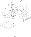
- a first embodiment of the invention provides a case latch assembly 10 comprising a first lock mounting part 12, a second lock mounting part 14, a hinge member 16, a strike plate member 18, a strike plate engagement member 20, a lock nut 22, a cam pin 24 and a coupling pin 26.
- first 12 and second 14 lock mounting parts comprise respective first and second mounting dishes.
- the mounting dishes 12, 14 together form a latch dish and are arranged to be respectively located on the lid and body of a case.
- Each mounting dish 12, 14 is arranged to be located in a respective aperture (not shown) in the case (not shown) so that the mounting dishes 12, 14 may be mounted substantially flush with a surface of the case.
- the strike plate member 18 is mounted on the first mounting dish 12 and defines a strike plate aperture 28.
- the case latch 10 further comprises a mounting element 30 and mounting pins 32.
- the mounting element 30 is provided on the second mounting dish 14 and is configured to receive the mounting pins 32.
- the hinge member 16 is provided with a mounting hook 34 at one end and an aperture 36. The mounting hook 34 is located around the mounting pins 32 such that the hinge member 16 is mounted for pivotable movement.
- the strike plate engagement member 20 is mounted for reciprocal linear movement on the hinge member 16.
- the strike plate engagement member 20 has a coupling slot 38 and a cam slot 40 provided in it.
- the coupling slot 38 extends generally lengthways and the cam slot 40 extends generally crossways.
- the strike plate engagement member 20 is provided with a strike plate hook 44 at the opposite end to the mounting hook 34.
- the hook 44 is configured to engage the strike plate member 18, through its aperture 28, when the strike plate engagement member 20 is in a closed, locked position.
- the lock nut 22 is rotatably mounted and is provided with an actuation key 42 for manual rotation of the lock nut 22 by a user.
- the cam pin 24 is connected to the lock nut 22 at an off-centre position and is located through and engaged with the cam slot 40.
- the coupling pin 26 is connected to the lock nut 22 at a second position and is located through the coupling slot 38. Both pins 24, 26 extend through the aperture 36 in the hinge member 36.
- the case latch assembly 10 is further provided with a number of fixing rivets 46.
- the case latch assembly 10 is operated by a user manually rotating the lock nut 22 with the actuation key 42.
- the rotation of the lock nut is translated by movement of the cam pin 24 within the cam slot 40 into linear movement of the strike plate engagement member 20 between a closed position and an extended position.
- the coupling pin 26 moves along the coupling slot 38.
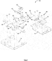
- a second embodiment of the invention provides a case latch assembly 50 as shown in Figures 2 and 3 .
- the case latch assembly 50 of this embodiment is similar to the latch assembly 10 of the first embodiment, with the following modifications.
- the same reference numbers are retained for corresponding features.
- a circular retaining aperture 52 is provided in the hinge member 16.
- the cam pin 24 and the coupling pin 26 are located through the retaining aperture which constrains their movement.
- the coupling slot 54 of this embodiment has a curved shaped, to more closely match the curved path of the coupling pin 26 during actuation of the case latch 50.
- the curved shape may constrain the path of the coupling pin without interfering with the motion of the strike plate engagement member 20, which may ensure smooth movement of the strike plate engagement member between the closed and extended positions.
- the cam slot 56 extends generally from the central region of the coupling slot 54.
- the coupling slot 54 and the cam slot 56 are provided together as a single generally mushroom-shaped slot.
- the hinge member 16 is mounted for pivotable movement on a pair of spring 58. The springs are configured to apply tension to the hinge member to thereby bias the strike plate engagement member 20 into the closed position.
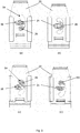
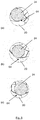
- Figure 3 illustrates movement of the strike plate engagement member 20 from the extended position ( Figure 3a ) through intermediate positions ( Figures 3b and 3c ) to the closed position ( Figure 3d ).
- the coupling pin 26 In the extended position the coupling pin 26 is located at one end of the coupling slot 54 and the cam pin 24 is located at the end of the cam slot 56 adjacent the coupling slot 54.
- the cam pin 24 As the lock nut 22 is rotated the cam pin 24 is moved to the distal end of the cam slot and the position of the coupling pin 26 moves along the coupling slot to the mid-point ( Figure 3b ).
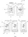
- a third embodiment of the invention provides a case latch assembly 60 part of which is shown in Figures 4 and 5 .
- the case latch assembly 60 of this embodiment is similar to the case latch assembly 50 shown in Figures 2 and 3 , with the following modifications.
- the same reference numbers are retained for corresponding features.
- the cam slot 62 has a retaining element 64 provided towards its end closest to the coupling slot 54.
- the retaining element is a nodule 64 extending from a wall of the cam slot 62.
- the retaining element is arranged to retain the cam pin at the end of the cam slot and therefore retains the strike plate engagement member in its closed position.
- the retaining element 64 may prevent the case latch 60 from opening accidentally, such as due to vibration or through being knocked.
- the cam pin 24 rides up and over the nodule 64 into and out of a retained position at the end of the cam slot 62.
- the strike plate engagement member 20 moves from the extended position ( Figure 4a ) into the closed position ( Figure 4e and 5c ) the cam pin 24 rides up one side of the nodule 64 ( Figure 5a ), over the nodule ( Figure 5b ) and down the other side of the nodule ( Figure 5c ) into the retained position. Movement out of the retained position is the reverse, i.e. Figures 5c to 5a .
Landscapes
- Engineering & Computer Science (AREA)
- Mechanical Engineering (AREA)
- Closures For Containers (AREA)
- Hinges (AREA)
Claims (12)
- Fangverriegelungsanordnung (10,50,60), umfassend:Ein Schließblechelement (18), das auf einem ersten Schlossmontageteil (12) versehen ist;ein Scharnierelement (16), das zur Drehbewegung auf einem zweiten Schlossmontageteil (14) befestigt ist;ein Eingriffselement (20) für das Schließblech, das am Scharnierelement für hin- und hergehende lineare Bewegung darauf befestigt ist und einen darin bereitgestellten Kupplungsschlitz (38, 54) aufweisend, der sich generell längs erstreckt und einen darin bereitgestellten Nockenschlitz (40, 56, 62) aufweist, der sich generell quer erstreckt;eine Sicherungsmutter (22), die drehbar zum Scharnierelement (16) montiert ist;einen Nockenstift (24), der mit der Sicherungsmutter (22) in einer exzentrischen Position verbunden und mit dem Nockenschlitz (40,56,62) in Eingriff ist; undeinen Kupplungsstift (26), der mit der Sicherungsmutter (22) in einer zweiten Position verbunden ist und durch den Kupplungsschlitz hindurch fixiert wird, wobei Drehung der Sicherungsmutter (22) durch Bewegung des Nockenstifts (24) innerhalb des Nockenschlitzes (40,56,62) in lineare Bewegung des Eingriffselements (20) des Schließblechs zwischen einer geschlossenen Position und einer erweiterten Position übersetzt wird und, wobei sich der Kupplungsstift (26), während der Drehung der Sicherungsmutter (22), dem Kupplungsschlitz (38,54) entlang bewegt.
- Fangverriegelungsanordnung wie in Anspruch 1 beansprucht, wobei der Kupplungsschlitz (54) eine gekrümmte Form aufweist.
- Fangverriegelungsanordnung wie in Anspruch 1 oder Anspruch 2 beansprucht, wobei sich der Nockenschlitz (40,56, 62) generell ab einem mittigen Bereich des Kupplungsschlitzes erstreckt.
- Fangverriegelungsanordnung wie in irgendeinem vorhergehenden Anspruch beansprucht, wobei der Kupplungsschlitz (54) und der Nockenschlitz (56, 62) zusammen als ein generell T-förmiger Schlitz oder ein generell pilzförmiger Schlitz bereitgestellt werden.
- Fangverriegelungsanordnung wie in irgendeinem vorhergehenden Anspruch beansprucht, wobei der Nockenschlitz (62) ein Halteelement (64) aufweist, das in Richtung seines dem Kupplungsschlitz am nächsten gelegenen Endes bereitgestellt ist.
- Fangverriegelungsanordnung wie in Anspruch 5 beansprucht, wobei das Halteelement (64) ein Knötchen ist, das sich ab einer Wand des Nockenschlitzes (62) erstreckt.
- Fangverriegelungsanordnung wie in irgendeinem vorhergehenden Anspruch beansprucht, wobei, eine generell runde Rückhalteöffnung (52) im Scharnierelement bereitgestellt ist und der Nockenstift
(24) und der Kupplungsstift (26) werden durch die Rückhalteöffnung hindurch fixiert. - Fangverriegelungsanordnung wie in irgendeinem vorhergehenden Anspruch beansprucht, wobei der Nockenstift
(24) und der Kupplungsstift (26) jeweils einen Kupplungsbund an einem Ende umfassen, der konfiguriert ist, sich mit einer Seite des Eingriffselements des Schließblechs zu kuppeln und die Sicherungsmutter (22) wird generell auf der anderen Seite des Eingriffselements (20 des Schließblechs bereitgestellt. - Fangverriegelungsanordnung wie in Anspruch 5 beansprucht, wobei der Nockenstift (24) und der Kupplungsstift (26) jeweils eine Niete umfassen.
- Fangverriegelungsanordnung wie in irgendeinem vorhergehenden Anspruch beansprucht, wobei das Scharnierelement (16) auf wenigstens einem Federelement (58) montiert ist, das konfiguriert ist, das Eingriffselement (20) des Schließblechs in die geschlossene Position vorzuspannen.
- Fangverriegelungsanordnung wie in Anspruch 10 beansprucht, wobei das wenigstens eine Federelement (58) eine Feder umfasst, die konfiguriert ist, Spannung auf das Scharnierelement (16) anzuwenden, um dadurch das Eingriffselement (20) des Schließblechs in die geschlossene Position vorzuspannen.
- Fangverriegelungsanordnung wie in irgendeinem vorhergehenden Anspruch beansprucht, wobei die ersten und zweite Schlossmontageteile jeweilige ersten und zweite Montageschalen (12, 14) umfassen, wobei die ersten und zweien Montageschalen ferner eine Schlossschale umfassen.
Priority Applications (2)
| Application Number | Priority Date | Filing Date | Title |
|---|---|---|---|
| EP12174757.0A EP2682549B1 (de) | 2012-07-03 | 2012-07-03 | Fangverriegelungsanordnung |
| US13/935,045 US20140042755A1 (en) | 2012-07-03 | 2013-07-03 | Case latch assembly |
Applications Claiming Priority (1)
| Application Number | Priority Date | Filing Date | Title |
|---|---|---|---|
| EP12174757.0A EP2682549B1 (de) | 2012-07-03 | 2012-07-03 | Fangverriegelungsanordnung |
Publications (2)
| Publication Number | Publication Date |
|---|---|
| EP2682549A1 EP2682549A1 (de) | 2014-01-08 |
| EP2682549B1 true EP2682549B1 (de) | 2016-05-25 |
Family
ID=46456408
Family Applications (1)
| Application Number | Title | Priority Date | Filing Date |
|---|---|---|---|
| EP12174757.0A Active EP2682549B1 (de) | 2012-07-03 | 2012-07-03 | Fangverriegelungsanordnung |
Country Status (2)
| Country | Link |
|---|---|
| US (1) | US20140042755A1 (de) |
| EP (1) | EP2682549B1 (de) |
Families Citing this family (7)
| Publication number | Priority date | Publication date | Assignee | Title |
|---|---|---|---|---|
| EP2907948B1 (de) | 2014-02-18 | 2016-11-09 | Penn Elcom Limited | Behälterverriegelungsanordnung |
| USD759457S1 (en) * | 2015-03-19 | 2016-06-21 | Hansen International, Inc. | Cable eye paddle handle element |
| US9512636B2 (en) | 2015-03-19 | 2016-12-06 | Hansen International, Inc. | Paddle handle with cable eye |
| US12006732B2 (en) | 2016-11-29 | 2024-06-11 | Fivetech Technology Inc. | Pull handle structure |
| TWM541180U (zh) * | 2016-11-29 | 2017-05-01 | 伍鐌科技股份有限公司 | 拉把結構 |
| US11840865B2 (en) | 2016-11-29 | 2023-12-12 | Fivetech Technology Inc. | Pull handle structure |
| DE102018101061B3 (de) * | 2018-01-18 | 2019-03-21 | Penn Elcom Ltd. | Montageschale, Riegelschloss, Deckel-Aufsteller mit verbesserter Dichtigkeit |
Family Cites Families (35)
| Publication number | Priority date | Publication date | Assignee | Title |
|---|---|---|---|---|
| US539030A (en) * | 1895-05-14 | Sash-lock | ||
| US309988A (en) * | 1884-12-30 | smith | ||
| US659069A (en) * | 1900-03-29 | 1900-10-02 | Hobart B Ives | Sash-lock. |
| DE420434C (de) * | 1923-10-07 | 1925-10-24 | Rheinische Tuerschliesserfabri | Tuerschloss |
| US1677825A (en) * | 1927-11-30 | 1928-07-17 | Alpheus M Hilty | Sash fastener |
| US2151219A (en) * | 1937-12-14 | 1939-03-21 | Curtis Companies Inc | Window sash lock |
| US2853751A (en) * | 1952-02-05 | 1958-09-30 | Simmons Fastener Corp | Link lock fastener |
| US2853752A (en) * | 1952-12-17 | 1958-09-30 | Simmons Fastener Corp | Positively locked link lock fastener |
| US2820995A (en) * | 1955-10-04 | 1958-01-28 | Schlueter Ernest | Spring loaded link lock fastener |
| US2873134A (en) * | 1957-04-25 | 1959-02-10 | Amerock Corp | Sash lock |
| US2997323A (en) * | 1959-12-08 | 1961-08-22 | Lawrence Brothers | Sash fastener |
| US3295877A (en) * | 1962-01-31 | 1967-01-03 | Gunnar E Swanson | Catch for packing case or the like |
| US3150893A (en) * | 1962-10-29 | 1964-09-29 | Hartwell Corp | Draw latch |
| US3204993A (en) * | 1963-04-12 | 1965-09-07 | Gunnar E Swanson | Spring loaded turn catch for packing case or the like |
| US4090727A (en) * | 1977-05-25 | 1978-05-23 | Simmons Fastener Corporation | Half-turn actuated member |
| US4560190A (en) * | 1983-02-25 | 1985-12-24 | J. H. Sessions & Son | Fastening assembly |
| US4522436A (en) * | 1983-04-06 | 1985-06-11 | Simmons Fastener Corporation | Spring-loaded toggle latch |
| US4746151A (en) * | 1985-08-12 | 1988-05-24 | Simmons Fastener Corporation | Half-turn industrial fastener |
| US4758031A (en) * | 1986-09-25 | 1988-07-19 | Thermodyne International Ltd. | Retractable safety latch for cases |
| US4958865A (en) * | 1988-08-18 | 1990-09-25 | Cheng Jin J | Clamping system |
| FR2641567B1 (fr) * | 1989-01-12 | 1995-07-21 | Zaoui Charles | Dispositif de serrure a entrainement de pene dormant perfectionne |
| US5511834A (en) | 1994-04-06 | 1996-04-30 | Penn Fabrication (U.S.A.) Inc. | Automatically positioned latch assembly |
| US5669638A (en) * | 1996-02-01 | 1997-09-23 | Southco, Inc. | Fastening device |
| GB9620065D0 (en) * | 1996-09-26 | 1996-11-13 | Protex Fasteners Ltd | Case catches |
| US5797635A (en) * | 1997-02-05 | 1998-08-25 | Penn Fabrication (U.S.A.) Inc. | Latch |
| USD457801S1 (en) * | 2001-04-16 | 2002-05-28 | Paul Zamberg | Surface mount latch |
| US20020149208A1 (en) * | 2001-04-16 | 2002-10-17 | Paul Zamberg | Latch mechanism |
| USD454478S1 (en) * | 2001-08-10 | 2002-03-19 | Penn Fabrication (U.S.A.) Inc. | Surface mount latch |
| USD576017S1 (en) * | 2005-08-22 | 2008-09-02 | Penn Fabrication Limited | Case latch |
| US20070252058A1 (en) * | 2006-03-27 | 2007-11-01 | Martin Drumm | Fastener for a transport container |
| EP1975354A1 (de) * | 2007-03-27 | 2008-10-01 | Penn Fabrication Limited | Behälterverriegelungsanordnung |
| WO2009047780A2 (en) * | 2007-05-25 | 2009-04-16 | Hegde Krishnaprasad S | A recessed mounting latch for a case |
| US8104802B2 (en) * | 2007-11-15 | 2012-01-31 | T.C.H. Sales, Inc. | Integrated recessed latch assembly |
| EP2063051B1 (de) * | 2007-11-26 | 2010-06-23 | Penn Fabrication Limited | Behälterverriegelungsanordnung |
| EP2508700B1 (de) * | 2011-04-06 | 2015-02-25 | Penn Elcom Limited | Behälterverriegelungsanordnung |
-
2012
- 2012-07-03 EP EP12174757.0A patent/EP2682549B1/de active Active
-
2013
- 2013-07-03 US US13/935,045 patent/US20140042755A1/en not_active Abandoned
Also Published As
| Publication number | Publication date |
|---|---|
| EP2682549A1 (de) | 2014-01-08 |
| US20140042755A1 (en) | 2014-02-13 |
Similar Documents
| Publication | Publication Date | Title |
|---|---|---|
| EP2682549B1 (de) | Fangverriegelungsanordnung | |
| EP2508701B1 (de) | Behälterverriegelungsanordnung | |
| US9345290B2 (en) | Bracelet and electronic device using the same | |
| KR101842834B1 (ko) | 폴딩도어 락 잠금장치 | |
| CN110324472A (zh) | 手机固定装置 | |
| US9353558B2 (en) | Case latch assembly | |
| CN118958789A (zh) | 静音磁力锁体 | |
| JP7578412B2 (ja) | 特に天然または人工皮革の物品を開放し閉鎖するための装置、およびこのような装置を含む物品 | |
| EP2063051A1 (de) | Behälterverriegelungsanordnung | |
| KR101732674B1 (ko) | 푸쉬풀 동작으로 개방되는 도어락 장치 | |
| JP5296576B2 (ja) | 門扉の係止装置および門扉 | |
| KR20210084953A (ko) | 카세트 핸들의 좌우수 전환조립체 | |
| JP5588124B2 (ja) | 係合装置 | |
| WO2014195928A1 (en) | Inside door handle with locking function using single cable | |
| JP5894218B2 (ja) | 磁石サイドロック | |
| KR101572628B1 (ko) | 래치볼트의 고정구조체 | |
| JP6262594B2 (ja) | 引戸用鎌錠 | |
| JP6978924B2 (ja) | アウトセット引戸用鎌錠 | |
| JP2017218812A (ja) | 車両のインサイドハンドル装置 | |
| US20120139267A1 (en) | Cushion structure of lock | |
| US10224161B2 (en) | Apparatus for operating a rotary switch | |
| WO2013114224A2 (en) | Lever door handle lock | |
| JP2013036288A (ja) | ラッチストライカ | |
| CN209942431U (zh) | 闩锁及闩锁组件 | |
| CN111315950B (zh) | 家用器具的门锁装置、具体地洗碗机的门锁装置 |
Legal Events
| Date | Code | Title | Description |
|---|---|---|---|
| PUAI | Public reference made under article 153(3) epc to a published international application that has entered the european phase |
Free format text: ORIGINAL CODE: 0009012 |
|
| AK | Designated contracting states |
Kind code of ref document: A1 Designated state(s): AL AT BE BG CH CY CZ DE DK EE ES FI FR GB GR HR HU IE IS IT LI LT LU LV MC MK MT NL NO PL PT RO RS SE SI SK SM TR |
|
| AX | Request for extension of the european patent |
Extension state: BA ME |
|
| 17P | Request for examination filed |
Effective date: 20140708 |
|
| RBV | Designated contracting states (corrected) |
Designated state(s): AL AT BE BG CH CY CZ DE DK EE ES FI FR GB GR HR HU IE IS IT LI LT LU LV MC MK MT NL NO PL PT RO RS SE SI SK SM TR |
|
| RIC1 | Information provided on ipc code assigned before grant |
Ipc: E05B 63/00 20060101ALI20151125BHEP Ipc: E05C 19/10 20060101AFI20151125BHEP |
|
| GRAP | Despatch of communication of intention to grant a patent |
Free format text: ORIGINAL CODE: EPIDOSNIGR1 |
|
| INTG | Intention to grant announced |
Effective date: 20160118 |
|
| GRAS | Grant fee paid |
Free format text: ORIGINAL CODE: EPIDOSNIGR3 |
|
| GRAA | (expected) grant |
Free format text: ORIGINAL CODE: 0009210 |
|
| AK | Designated contracting states |
Kind code of ref document: B1 Designated state(s): AL AT BE BG CH CY CZ DE DK EE ES FI FR GB GR HR HU IE IS IT LI LT LU LV MC MK MT NL NO PL PT RO RS SE SI SK SM TR |
|
| REG | Reference to a national code |
Ref country code: GB Ref legal event code: FG4D |
|
| REG | Reference to a national code |
Ref country code: CH Ref legal event code: EP |
|
| REG | Reference to a national code |
Ref country code: IE Ref legal event code: FG4D Ref country code: AT Ref legal event code: REF Ref document number: 802480 Country of ref document: AT Kind code of ref document: T Effective date: 20160615 |
|
| REG | Reference to a national code |
Ref country code: DE Ref legal event code: R096 Ref document number: 602012018886 Country of ref document: DE |
|
| REG | Reference to a national code |
Ref country code: LT Ref legal event code: MG4D |
|
| REG | Reference to a national code |
Ref country code: NL Ref legal event code: MP Effective date: 20160525 |
|
| PG25 | Lapsed in a contracting state [announced via postgrant information from national office to epo] |
Ref country code: FI Free format text: LAPSE BECAUSE OF FAILURE TO SUBMIT A TRANSLATION OF THE DESCRIPTION OR TO PAY THE FEE WITHIN THE PRESCRIBED TIME-LIMIT Effective date: 20160525 Ref country code: NO Free format text: LAPSE BECAUSE OF FAILURE TO SUBMIT A TRANSLATION OF THE DESCRIPTION OR TO PAY THE FEE WITHIN THE PRESCRIBED TIME-LIMIT Effective date: 20160825 Ref country code: LT Free format text: LAPSE BECAUSE OF FAILURE TO SUBMIT A TRANSLATION OF THE DESCRIPTION OR TO PAY THE FEE WITHIN THE PRESCRIBED TIME-LIMIT Effective date: 20160525 Ref country code: NL Free format text: LAPSE BECAUSE OF FAILURE TO SUBMIT A TRANSLATION OF THE DESCRIPTION OR TO PAY THE FEE WITHIN THE PRESCRIBED TIME-LIMIT Effective date: 20160525 |
|
| REG | Reference to a national code |
Ref country code: AT Ref legal event code: MK05 Ref document number: 802480 Country of ref document: AT Kind code of ref document: T Effective date: 20160525 |
|
| PG25 | Lapsed in a contracting state [announced via postgrant information from national office to epo] |
Ref country code: ES Free format text: LAPSE BECAUSE OF FAILURE TO SUBMIT A TRANSLATION OF THE DESCRIPTION OR TO PAY THE FEE WITHIN THE PRESCRIBED TIME-LIMIT Effective date: 20160525 Ref country code: LV Free format text: LAPSE BECAUSE OF FAILURE TO SUBMIT A TRANSLATION OF THE DESCRIPTION OR TO PAY THE FEE WITHIN THE PRESCRIBED TIME-LIMIT Effective date: 20160525 Ref country code: RS Free format text: LAPSE BECAUSE OF FAILURE TO SUBMIT A TRANSLATION OF THE DESCRIPTION OR TO PAY THE FEE WITHIN THE PRESCRIBED TIME-LIMIT Effective date: 20160525 Ref country code: PT Free format text: LAPSE BECAUSE OF FAILURE TO SUBMIT A TRANSLATION OF THE DESCRIPTION OR TO PAY THE FEE WITHIN THE PRESCRIBED TIME-LIMIT Effective date: 20160926 Ref country code: SE Free format text: LAPSE BECAUSE OF FAILURE TO SUBMIT A TRANSLATION OF THE DESCRIPTION OR TO PAY THE FEE WITHIN THE PRESCRIBED TIME-LIMIT Effective date: 20160525 Ref country code: GR Free format text: LAPSE BECAUSE OF FAILURE TO SUBMIT A TRANSLATION OF THE DESCRIPTION OR TO PAY THE FEE WITHIN THE PRESCRIBED TIME-LIMIT Effective date: 20160826 |
|
| PG25 | Lapsed in a contracting state [announced via postgrant information from national office to epo] |
Ref country code: BE Free format text: LAPSE BECAUSE OF NON-PAYMENT OF DUE FEES Effective date: 20160731 Ref country code: IT Free format text: LAPSE BECAUSE OF FAILURE TO SUBMIT A TRANSLATION OF THE DESCRIPTION OR TO PAY THE FEE WITHIN THE PRESCRIBED TIME-LIMIT Effective date: 20160525 |
|
| PG25 | Lapsed in a contracting state [announced via postgrant information from national office to epo] |
Ref country code: SK Free format text: LAPSE BECAUSE OF FAILURE TO SUBMIT A TRANSLATION OF THE DESCRIPTION OR TO PAY THE FEE WITHIN THE PRESCRIBED TIME-LIMIT Effective date: 20160525 Ref country code: DK Free format text: LAPSE BECAUSE OF FAILURE TO SUBMIT A TRANSLATION OF THE DESCRIPTION OR TO PAY THE FEE WITHIN THE PRESCRIBED TIME-LIMIT Effective date: 20160525 Ref country code: CZ Free format text: LAPSE BECAUSE OF FAILURE TO SUBMIT A TRANSLATION OF THE DESCRIPTION OR TO PAY THE FEE WITHIN THE PRESCRIBED TIME-LIMIT Effective date: 20160525 Ref country code: EE Free format text: LAPSE BECAUSE OF FAILURE TO SUBMIT A TRANSLATION OF THE DESCRIPTION OR TO PAY THE FEE WITHIN THE PRESCRIBED TIME-LIMIT Effective date: 20160525 Ref country code: RO Free format text: LAPSE BECAUSE OF FAILURE TO SUBMIT A TRANSLATION OF THE DESCRIPTION OR TO PAY THE FEE WITHIN THE PRESCRIBED TIME-LIMIT Effective date: 20160525 |
|
| PG25 | Lapsed in a contracting state [announced via postgrant information from national office to epo] |
Ref country code: SM Free format text: LAPSE BECAUSE OF FAILURE TO SUBMIT A TRANSLATION OF THE DESCRIPTION OR TO PAY THE FEE WITHIN THE PRESCRIBED TIME-LIMIT Effective date: 20160525 Ref country code: BE Free format text: LAPSE BECAUSE OF FAILURE TO SUBMIT A TRANSLATION OF THE DESCRIPTION OR TO PAY THE FEE WITHIN THE PRESCRIBED TIME-LIMIT Effective date: 20160525 Ref country code: AT Free format text: LAPSE BECAUSE OF FAILURE TO SUBMIT A TRANSLATION OF THE DESCRIPTION OR TO PAY THE FEE WITHIN THE PRESCRIBED TIME-LIMIT Effective date: 20160525 Ref country code: PL Free format text: LAPSE BECAUSE OF FAILURE TO SUBMIT A TRANSLATION OF THE DESCRIPTION OR TO PAY THE FEE WITHIN THE PRESCRIBED TIME-LIMIT Effective date: 20160525 |
|
| REG | Reference to a national code |
Ref country code: DE Ref legal event code: R097 Ref document number: 602012018886 Country of ref document: DE Ref country code: CH Ref legal event code: PL |
|
| PG25 | Lapsed in a contracting state [announced via postgrant information from national office to epo] |
Ref country code: MC Free format text: LAPSE BECAUSE OF FAILURE TO SUBMIT A TRANSLATION OF THE DESCRIPTION OR TO PAY THE FEE WITHIN THE PRESCRIBED TIME-LIMIT Effective date: 20160525 |
|
| PLBE | No opposition filed within time limit |
Free format text: ORIGINAL CODE: 0009261 |
|
| STAA | Information on the status of an ep patent application or granted ep patent |
Free format text: STATUS: NO OPPOSITION FILED WITHIN TIME LIMIT |
|
| PG25 | Lapsed in a contracting state [announced via postgrant information from national office to epo] |
Ref country code: CH Free format text: LAPSE BECAUSE OF NON-PAYMENT OF DUE FEES Effective date: 20160731 Ref country code: LI Free format text: LAPSE BECAUSE OF NON-PAYMENT OF DUE FEES Effective date: 20160731 Ref country code: FR Free format text: LAPSE BECAUSE OF NON-PAYMENT OF DUE FEES Effective date: 20160801 |
|
| REG | Reference to a national code |
Ref country code: FR Ref legal event code: ST Effective date: 20170331 |
|
| 26N | No opposition filed |
Effective date: 20170228 |
|
| REG | Reference to a national code |
Ref country code: IE Ref legal event code: MM4A |
|
| PG25 | Lapsed in a contracting state [announced via postgrant information from national office to epo] |
Ref country code: SI Free format text: LAPSE BECAUSE OF FAILURE TO SUBMIT A TRANSLATION OF THE DESCRIPTION OR TO PAY THE FEE WITHIN THE PRESCRIBED TIME-LIMIT Effective date: 20160525 |
|
| PG25 | Lapsed in a contracting state [announced via postgrant information from national office to epo] |
Ref country code: IE Free format text: LAPSE BECAUSE OF NON-PAYMENT OF DUE FEES Effective date: 20160703 |
|
| PG25 | Lapsed in a contracting state [announced via postgrant information from national office to epo] |
Ref country code: LU Free format text: LAPSE BECAUSE OF NON-PAYMENT OF DUE FEES Effective date: 20160703 |
|
| PG25 | Lapsed in a contracting state [announced via postgrant information from national office to epo] |
Ref country code: CY Free format text: LAPSE BECAUSE OF FAILURE TO SUBMIT A TRANSLATION OF THE DESCRIPTION OR TO PAY THE FEE WITHIN THE PRESCRIBED TIME-LIMIT Effective date: 20160525 Ref country code: HU Free format text: LAPSE BECAUSE OF FAILURE TO SUBMIT A TRANSLATION OF THE DESCRIPTION OR TO PAY THE FEE WITHIN THE PRESCRIBED TIME-LIMIT; INVALID AB INITIO Effective date: 20120703 |
|
| PG25 | Lapsed in a contracting state [announced via postgrant information from national office to epo] |
Ref country code: MK Free format text: LAPSE BECAUSE OF FAILURE TO SUBMIT A TRANSLATION OF THE DESCRIPTION OR TO PAY THE FEE WITHIN THE PRESCRIBED TIME-LIMIT Effective date: 20160525 Ref country code: IS Free format text: LAPSE BECAUSE OF FAILURE TO SUBMIT A TRANSLATION OF THE DESCRIPTION OR TO PAY THE FEE WITHIN THE PRESCRIBED TIME-LIMIT Effective date: 20160525 Ref country code: TR Free format text: LAPSE BECAUSE OF FAILURE TO SUBMIT A TRANSLATION OF THE DESCRIPTION OR TO PAY THE FEE WITHIN THE PRESCRIBED TIME-LIMIT Effective date: 20160525 Ref country code: MT Free format text: LAPSE BECAUSE OF NON-PAYMENT OF DUE FEES Effective date: 20160731 Ref country code: HR Free format text: LAPSE BECAUSE OF FAILURE TO SUBMIT A TRANSLATION OF THE DESCRIPTION OR TO PAY THE FEE WITHIN THE PRESCRIBED TIME-LIMIT Effective date: 20160525 |
|
| PG25 | Lapsed in a contracting state [announced via postgrant information from national office to epo] |
Ref country code: BG Free format text: LAPSE BECAUSE OF FAILURE TO SUBMIT A TRANSLATION OF THE DESCRIPTION OR TO PAY THE FEE WITHIN THE PRESCRIBED TIME-LIMIT Effective date: 20160525 |
|
| PG25 | Lapsed in a contracting state [announced via postgrant information from national office to epo] |
Ref country code: AL Free format text: LAPSE BECAUSE OF FAILURE TO SUBMIT A TRANSLATION OF THE DESCRIPTION OR TO PAY THE FEE WITHIN THE PRESCRIBED TIME-LIMIT Effective date: 20160525 |
|
| PGFP | Annual fee paid to national office [announced via postgrant information from national office to epo] |
Ref country code: DE Payment date: 20250714 Year of fee payment: 14 |
|
| PGFP | Annual fee paid to national office [announced via postgrant information from national office to epo] |
Ref country code: GB Payment date: 20250710 Year of fee payment: 14 |