EP2682590A2 - Turbinengeneratoranordnung zur Schubvektorsteuerung - Google Patents
Turbinengeneratoranordnung zur Schubvektorsteuerung Download PDFInfo
- Publication number
- EP2682590A2 EP2682590A2 EP20130170548 EP13170548A EP2682590A2 EP 2682590 A2 EP2682590 A2 EP 2682590A2 EP 20130170548 EP20130170548 EP 20130170548 EP 13170548 A EP13170548 A EP 13170548A EP 2682590 A2 EP2682590 A2 EP 2682590A2
- Authority
- EP
- European Patent Office
- Prior art keywords
- turbine
- gear
- generator
- speed control
- control valve
- Prior art date
- Legal status (The legal status is an assumption and is not a legal conclusion. Google has not performed a legal analysis and makes no representation as to the accuracy of the status listed.)
- Withdrawn
Links
- 239000003380 propellant Substances 0.000 claims abstract description 25
- 238000000034 method Methods 0.000 claims abstract description 11
- 239000010687 lubricating oil Substances 0.000 claims description 16
- 239000003921 oil Substances 0.000 claims description 14
- 239000000446 fuel Substances 0.000 claims description 10
- 238000001816 cooling Methods 0.000 claims description 8
- 239000007788 liquid Substances 0.000 claims description 5
- 239000001257 hydrogen Substances 0.000 claims description 4
- 229910052739 hydrogen Inorganic materials 0.000 claims description 4
- 238000005461 lubrication Methods 0.000 claims description 4
- UFHFLCQGNIYNRP-UHFFFAOYSA-N Hydrogen Chemical compound [H][H] UFHFLCQGNIYNRP-UHFFFAOYSA-N 0.000 claims description 3
- 230000001276 controlling effect Effects 0.000 claims 3
- 230000001105 regulatory effect Effects 0.000 claims 2
- 239000007789 gas Substances 0.000 description 5
- 238000010586 diagram Methods 0.000 description 2
- 238000005516 engineering process Methods 0.000 description 2
- 230000000712 assembly Effects 0.000 description 1
- 238000000429 assembly Methods 0.000 description 1
- 239000012530 fluid Substances 0.000 description 1
- 150000002431 hydrogen Chemical class 0.000 description 1
- 239000007800 oxidant agent Substances 0.000 description 1
- 238000011144 upstream manufacturing Methods 0.000 description 1
Images


Classifications
-
- F—MECHANICAL ENGINEERING; LIGHTING; HEATING; WEAPONS; BLASTING
- F02—COMBUSTION ENGINES; HOT-GAS OR COMBUSTION-PRODUCT ENGINE PLANTS
- F02K—JET-PROPULSION PLANTS
- F02K1/00—Plants characterised by the form or arrangement of the jet pipe or nozzle; Jet pipes or nozzles peculiar thereto
- F02K1/54—Nozzles having means for reversing jet thrust
- F02K1/76—Control or regulation of thrust reversers
-
- F—MECHANICAL ENGINEERING; LIGHTING; HEATING; WEAPONS; BLASTING
- F02—COMBUSTION ENGINES; HOT-GAS OR COMBUSTION-PRODUCT ENGINE PLANTS
- F02K—JET-PROPULSION PLANTS
- F02K1/00—Plants characterised by the form or arrangement of the jet pipe or nozzle; Jet pipes or nozzles peculiar thereto
- F02K1/002—Plants characterised by the form or arrangement of the jet pipe or nozzle; Jet pipes or nozzles peculiar thereto with means to modify the direction of thrust vector
-
- F—MECHANICAL ENGINEERING; LIGHTING; HEATING; WEAPONS; BLASTING
- F02—COMBUSTION ENGINES; HOT-GAS OR COMBUSTION-PRODUCT ENGINE PLANTS
- F02K—JET-PROPULSION PLANTS
- F02K9/00—Rocket-engine plants, i.e. plants carrying both fuel and oxidant therefor; Control thereof
- F02K9/80—Rocket-engine plants, i.e. plants carrying both fuel and oxidant therefor; Control thereof characterised by thrust or thrust vector control
-
- F—MECHANICAL ENGINEERING; LIGHTING; HEATING; WEAPONS; BLASTING
- F02—COMBUSTION ENGINES; HOT-GAS OR COMBUSTION-PRODUCT ENGINE PLANTS
- F02K—JET-PROPULSION PLANTS
- F02K9/00—Rocket-engine plants, i.e. plants carrying both fuel and oxidant therefor; Control thereof
- F02K9/80—Rocket-engine plants, i.e. plants carrying both fuel and oxidant therefor; Control thereof characterised by thrust or thrust vector control
- F02K9/805—Rocket-engine plants, i.e. plants carrying both fuel and oxidant therefor; Control thereof characterised by thrust or thrust vector control servo-mechanisms or control devices therefor
-
- F—MECHANICAL ENGINEERING; LIGHTING; HEATING; WEAPONS; BLASTING
- F16—ENGINEERING ELEMENTS AND UNITS; GENERAL MEASURES FOR PRODUCING AND MAINTAINING EFFECTIVE FUNCTIONING OF MACHINES OR INSTALLATIONS; THERMAL INSULATION IN GENERAL
- F16H—GEARING
- F16H47/00—Combinations of mechanical gearing with fluid clutches or fluid gearing
- F16H47/02—Combinations of mechanical gearing with fluid clutches or fluid gearing the fluid gearing being of the volumetric type
-
- F—MECHANICAL ENGINEERING; LIGHTING; HEATING; WEAPONS; BLASTING
- F16—ENGINEERING ELEMENTS AND UNITS; GENERAL MEASURES FOR PRODUCING AND MAINTAINING EFFECTIVE FUNCTIONING OF MACHINES OR INSTALLATIONS; THERMAL INSULATION IN GENERAL
- F16H—GEARING
- F16H47/00—Combinations of mechanical gearing with fluid clutches or fluid gearing
- F16H47/06—Combinations of mechanical gearing with fluid clutches or fluid gearing the fluid gearing being of the hydrokinetic type
-
- F—MECHANICAL ENGINEERING; LIGHTING; HEATING; WEAPONS; BLASTING
- F16—ENGINEERING ELEMENTS AND UNITS; GENERAL MEASURES FOR PRODUCING AND MAINTAINING EFFECTIVE FUNCTIONING OF MACHINES OR INSTALLATIONS; THERMAL INSULATION IN GENERAL
- F16H—GEARING
- F16H48/00—Differential gearings
- F16H48/20—Arrangements for suppressing or influencing the differential action, e.g. locking devices
- F16H48/30—Arrangements for suppressing or influencing the differential action, e.g. locking devices using externally-actuatable means
-
- H—ELECTRICITY
- H02—GENERATION; CONVERSION OR DISTRIBUTION OF ELECTRIC POWER
- H02K—DYNAMO-ELECTRIC MACHINES
- H02K7/00—Arrangements for handling mechanical energy structurally associated with dynamo-electric machines, e.g. structural association with mechanical driving motors or auxiliary dynamo-electric machines
- H02K7/10—Structural association with clutches, brakes, gears, pulleys or mechanical starters
- H02K7/116—Structural association with clutches, brakes, gears, pulleys or mechanical starters with gears
Definitions
- the present invention is related to thrust actuation, and in particular to a system and method for providing electromechanical power to thrust actuators of space launch vehicles.
- Thrust vector control is the ability of a vehicle, such as a space launch vehicle, to control the direction of thrust from its engines in order to control its flight path or angular velocity. This is typically done through the use of actuators.
- the actuators control the deflection of a nozzle, which in turn adjusts the thrust vector of the space launch vehicle.
- Hydraulic power was generated by turbine pump assemblies that used pressurized gas to spin a turbine which drove a hydraulic pump. These hydraulic systems are becoming obsolete as vehicles move toward all-electric systems.
- a system includes a thrust system, a generator, a turbine, a speed control valve, and a gear assembly.
- the generator provides electric power to at least one electromechanical actuator of the thrust system.
- the turbine drives the generator.
- the speed control valve meters propellant to the turbine, and the gear assembly connects the turbine, the generator, and the speed control valve.
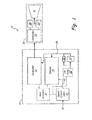
- FIG. 1 is a block diagram illustrating a system for providing thrust to a space launch vehicle according to an embodiment of the present invention.
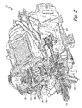
- FIG. 2 is a schematic cross section of a turbine generator assembly for providing electric power to an electromechanical thrust vector control system of a thrust system of a space launch vehicle according to an embodiment of the present invention.
- FIG. 3 is a schematic cross section showing a gear system along with a generator according to an embodiment of the present invention.
- FIG. 4 is a flowchart illustrating a method of providing electric power to an electromechanical thrust vector control system of a thrust system of a space launch vehicle according to an embodiment of the present invention.
- the present invention is a turbine generator system whereby the generator supplies electric power to electromechanical thrust vectoring actuators of a rocket engine on a space launch vehicle.
- a small fraction (approximately 0.1%) of liquid hydrogen fuel is diverted from the main fuel line of the rocket engine, and evaporated.
- the resulting gas is received by a turbine, and serves as a high-pressure working fluid that drives the turbine.
- This turbine in turn drives a generator which provides electric power to electromechanical actuators.
- These electromechanical actuators adjust the deflection of a nozzle, thereby controlling the rocket thrust vector.
- the speed of the turbine is controlled by a speed control valve.
- the speed control valve meters propellant to the turbine and is mechanically governed based upon the operating speed of the turbine.
- FIG. 1 is a block diagram illustrating a system 10 for powering a thrust system of a space launch vehicle according to an embodiment of the present invention.
- System 10 includes turbine generator assembly 12, (which includes turbine 14, generator 16, gear assembly 18, speed control valve 20, lube oil pump 22, lube oil filter 24, lube oil bypass valve 26, and cooling circuit 28), thrust system 30, (which includes controller 32, thrust vectoring actuators 34, and nozzle 36), propellant inlet 38, and metered propellant path 40.
- Turbine 14 is any turbine known in the art such as, for example, a single stage, multiple nozzle impulse turbine.
- Generator 16 is any electric generator known in the art.
- Liquid fuel such as hydrogen fuel
- Speed control valve 20 regulates the amount of gas provided to spin turbine 14.
- Turbine 14 powers generator 16 through gear assembly 18.
- Generator 16 generates electric power and provides electric power to thrust system 24.
- Thrust system 24 utilizes the electric power provided by generator 16 to power controller 32 and thrust vectoring actuators 34.
- Thrust vectoring actuators 34 may be implemented as, for example, two conventional, motor-driven linear electromechanical actuators oriented on normal axes (approximately 100 horsepower for each actuator).
- Controller 32 is any microcontroller such as, for example, a field programmable gate array (FPGA).
- Thrust vectoring actuators 34 adjust the deflection of nozzle 36, thereby controlling the rocket thrust vector.
- FPGA field programmable gate array
- Lube oil pump 22 is a standard lube oil pump known in the art and is contained in a reservoir housing. Oil pump 22 provides lubrication and cooling to both turbine 14 and generator 16 through cooling circuit 28. Oil is first passed through filter 24. The oil then exits gear assembly 18, travels through cooling circuit 28, and then re-enters gear assembly 18. Filter bypass valve 26 allows oil to bypass filter 24 if filter 24 is clogged. This is accomplished by measuring the oil pressure at filter bypass valve 24. For example, if the pressure at filter bypass valve 24 is greater than a maximum value, such as 300 pounds per square inch (PSI), unfiltered oil bypasses filter 24 to turbine 14 so as not to starve turbine 14 of oil. A separate valve may set the oil pressure in cooling circuit 28 to, for example, 65 PSI downstream of filter 24.
- PSI pounds per square inch
- FIG. 2 is a schematic cross section of a turbine generator assembly 12 for providing to an electromechanical thrust vector control system of thrust system 30 ( FIG. 1 ) of a space launch vehicle according to an embodiment of the present invention.
- Assembly 12 includes turbine 14, turbine shaft 50, spur gear 52, intermediate gears 54 and 56, output gear 58, spline shaft 60, speed control valve 20, poppet 62, governor flyweights 64, lube oil pump 22, lube oil restricting manifold 66, oil reservoir 68, propellant inlet 38, and speed adjustment screw 70.
- Speed control valve 20 mechanically meters propellant to turbine 14 to control the speed of turbine generator assembly 12.
- Liquid fuel such as liquid hydrogen
- speed control valve 20 is diverted from the main fuel line of the rocket engine. This propellant is received by speed control valve 20 from propellant inlet 38.
- the metered propellant is provided to turbine 14 through metered propellant path 40.
- Turbine 14 receives this propellant and powers spur gear 52.
- Spur gear 52 drives intermediate gears 54 and 56.
- Intermediate gear 56 drives a larger diameter output gear 58.
- Output gear 58 spins governor flyweights 64. Flyweights 64, due to centrifugal force, are driven radially outward, which axially drives poppet 62 based upon the rotational speed of output gear 58.
- Poppet 62 governs speed control valve 20, and in turn, the amount of propellant provided to turbine 14.
- Speed adjustment screw 70 is adjusted to control the operating speed of turbine 14 by preloading a spring to control governor flyweights 64.
- Output gear 48 also drives spline shaft 60 to control lube oil pump 22.
- Lube oil restricting manifold 66 is upstream of turbine 14.
- Manifold 66 drops the pressure of the oil provided to turbine 14 from lube oil pump 22. The pressure is dropped from, for example, 65 PSI to 10 PSI. This is to ensure that turbine bearings are not provided with too much oil. Losses can occur, and excess heat can be generated if too much oil is provided to the turbine bearings.
- FIG. 3 is a schematic cross section showing gear assembly 18 along with generator 16 according to an embodiment of the present invention.
- Intermediate gear 54 drives generator output gear 80.
- Generator output gear in turn spins generator output shaft 82.
- Output shaft 82 turns generator 16.
- Generator 16 produces electric energy that is provided to thrust system 30.
- FIG. 3 also displays metered propellant path 40.
- FIG. 4 is a flowchart illustrating a method 90 for providing thrust vectoring control to a space launch vehicle according to an embodiment of the present invention.
- gaseous fuel is provided to speed control valve 20 from the main fuel line of the rocket.
- speed control valve 20 meters propellant to turn turbine 14.
- turbine 14 powers spur gear 52, which turns three intermediate gears 54, 56 and 80.
- intermediate gear 80 turns generator 16 to generate electric power that is used by controller 32 and electromechanical thrust vector actuators 34 to control the thrust vector of nozzle 36.
- intermediate gear 54 turns output gear 58 which drives governor flyweights 64, and turns spline shaft 60 to power lube oil pump 22.
- flyweights 64 drive poppet 62 to meter propellant to turbine 14.
- the present invention describes a system and method for providing electromechanical power to thrust actuators of space launch vehicles.
Landscapes
- Engineering & Computer Science (AREA)
- Chemical & Material Sciences (AREA)
- Combustion & Propulsion (AREA)
- Mechanical Engineering (AREA)
- General Engineering & Computer Science (AREA)
- Control Of Eletrric Generators (AREA)
- Connection Of Motors, Electrical Generators, Mechanical Devices, And The Like (AREA)
- Control Of Turbines (AREA)
- Motor Or Generator Cooling System (AREA)
Applications Claiming Priority (1)
| Application Number | Priority Date | Filing Date | Title |
|---|---|---|---|
| US13/541,585 US9097210B2 (en) | 2012-07-03 | 2012-07-03 | Turbine generator assembly for thrust vector control |
Publications (1)
| Publication Number | Publication Date |
|---|---|
| EP2682590A2 true EP2682590A2 (de) | 2014-01-08 |
Family
ID=48607081
Family Applications (1)
| Application Number | Title | Priority Date | Filing Date |
|---|---|---|---|
| EP20130170548 Withdrawn EP2682590A2 (de) | 2012-07-03 | 2013-06-05 | Turbinengeneratoranordnung zur Schubvektorsteuerung |
Country Status (3)
| Country | Link |
|---|---|
| US (1) | US9097210B2 (de) |
| EP (1) | EP2682590A2 (de) |
| CN (1) | CN103527347A (de) |
Cited By (2)
| Publication number | Priority date | Publication date | Assignee | Title |
|---|---|---|---|---|
| EP3085941A1 (de) * | 2015-04-24 | 2016-10-26 | Hamilton Sundstrand Corporation | Passive, überdrehzahlgesteuerte turbopumpenanordnung sowie ein schubvektorsteuerungssystem für raketenmotoren umfassend eine solche anordnung |
| EP3153692A1 (de) * | 2015-10-09 | 2017-04-12 | Hamilton Sundstrand Corporation | Temperaturregelungsventil, turbinenpumpenanordnung und verfahren zur anpassung des flusses durch ein ventil |
Families Citing this family (5)
| Publication number | Priority date | Publication date | Assignee | Title |
|---|---|---|---|---|
| CN104358625B (zh) * | 2014-07-11 | 2016-05-18 | 中国航天科技集团公司第六研究院第十一研究所 | 一种变推力发动机推力闭环控制的方法 |
| US20170122328A1 (en) * | 2015-11-04 | 2017-05-04 | Hamilton Sundstrand Corporation | Hydraulic pump systems |
| US20170204865A1 (en) * | 2016-01-18 | 2017-07-20 | Hamilton Sundstrand Corporation | Emergency shutdown system for turbine pump assembly |
| US11286886B2 (en) * | 2019-04-14 | 2022-03-29 | Hamilton Sundstrand Corporation | Distributed fuel modules with hydraulic flow circuit breakers and gaseous flow circuit breakers |
| US11349264B2 (en) * | 2019-08-05 | 2022-05-31 | Raytheon Technologies Corporation | Capacitor-based connector for coaxial cable |
Family Cites Families (15)
| Publication number | Priority date | Publication date | Assignee | Title |
|---|---|---|---|---|
| US2004019A (en) * | 1931-07-14 | 1935-06-04 | Swetenham Charles Condon | Power transmission |
| US2357041A (en) * | 1942-01-20 | 1944-08-29 | Raymond L Woolley | Power plant |
| US2432358A (en) * | 1944-03-07 | 1947-12-09 | Gen Electric | Power plant |
| US2659529A (en) * | 1945-06-02 | 1953-11-17 | Lockheed Aircraft Corp | Cooling means for the rotors of gas turbine power plants |
| US2865227A (en) * | 1952-06-04 | 1958-12-23 | Gen Motors Corp | Transmission control system |
| US2822667A (en) * | 1954-02-03 | 1958-02-11 | Garrett Corp | Propellant feed system |
| US2856175A (en) * | 1954-08-19 | 1958-10-14 | Gen Motors Corp | Isochronous governing mechanism |
| US3052252A (en) * | 1956-01-30 | 1962-09-04 | Bendix Corp | Speed control system for turbine and liquid pressure supply device |
| US2922429A (en) * | 1956-09-28 | 1960-01-26 | Garrett Corp | Overspeed prevention means for turbines |
| US3145532A (en) * | 1961-07-27 | 1964-08-25 | Plessey Co Ltd | Gas-turbine operated engine starters |
| US3180088A (en) * | 1962-11-13 | 1965-04-27 | Aerojet General Co | Speed control system for turbine |
| US3769790A (en) * | 1972-03-20 | 1973-11-06 | Gen Motors Corp | Gas turbine lubrication |
| DE3737844C1 (de) * | 1987-11-04 | 1989-02-16 | Mannesmann Ag | Schmiereinrichtung fuer eine Turbomaschine |
| US7194863B2 (en) * | 2004-09-01 | 2007-03-27 | Honeywell International, Inc. | Turbine speed control system and method |
| US8727284B2 (en) * | 2010-01-22 | 2014-05-20 | Hamilton Sundstrand Corporation | Turbine powered electromechanical actuation system |
-
2012
- 2012-07-03 US US13/541,585 patent/US9097210B2/en active Active
-
2013
- 2013-06-05 EP EP20130170548 patent/EP2682590A2/de not_active Withdrawn
- 2013-07-03 CN CN201310276640.0A patent/CN103527347A/zh active Pending
Non-Patent Citations (1)
| Title |
|---|
| None |
Cited By (5)
| Publication number | Priority date | Publication date | Assignee | Title |
|---|---|---|---|---|
| EP3085941A1 (de) * | 2015-04-24 | 2016-10-26 | Hamilton Sundstrand Corporation | Passive, überdrehzahlgesteuerte turbopumpenanordnung sowie ein schubvektorsteuerungssystem für raketenmotoren umfassend eine solche anordnung |
| US10167732B2 (en) | 2015-04-24 | 2019-01-01 | Hamilton Sundstrand Corporation | Passive overspeed controlled turbo pump assembly |
| EP3153692A1 (de) * | 2015-10-09 | 2017-04-12 | Hamilton Sundstrand Corporation | Temperaturregelungsventil, turbinenpumpenanordnung und verfahren zur anpassung des flusses durch ein ventil |
| US20170102722A1 (en) * | 2015-10-09 | 2017-04-13 | Hamilton Sundstrand Corporation | Temperature adjusting valve, a turbine pump assembly and method of adjusting flow through a valve |
| US10331147B2 (en) | 2015-10-09 | 2019-06-25 | Hamilton Sundstrand Corporation | Temperature adjusting valve, a turbine pump assembly and method of adjusting flow through a valve |
Also Published As
| Publication number | Publication date |
|---|---|
| CN103527347A (zh) | 2014-01-22 |
| US20140007555A1 (en) | 2014-01-09 |
| US9097210B2 (en) | 2015-08-04 |
Similar Documents
| Publication | Publication Date | Title |
|---|---|---|
| US9097210B2 (en) | Turbine generator assembly for thrust vector control | |
| US8484977B2 (en) | Regulating the flow rate of fuel taken from a fuel circuit of an aircraft propelled by an engine | |
| US9091216B2 (en) | Systems and methods for changing a speed of a compressor boost stage in a gas turbine | |
| EP3051103B1 (de) | Brennstoffsystem | |
| US8166765B2 (en) | Fuel delivery and control system including a variable displacement actuation pump supplementing a fixed displacement main pump | |
| US7895819B2 (en) | Assistance and emergency backup for the electrical drive of a fuel pump in a turbine engine | |
| US6675570B2 (en) | Low-cost general aviation fuel control system | |
| EP2093400A2 (de) | Elektrisch-mechanisches Hybrid-Kraftstoffzufuhrsystem eines Turbinentriebwerks | |
| US8739811B2 (en) | Direct metering fuel system with constant servo flow | |
| CN110234857B (zh) | 用于向涡轮机供应燃料的系统 | |
| CA2818066A1 (fr) | Procede et systeme de regulation de fourniture d'air comprime a un reseau pneumatique, en particulier d'aeronef | |
| CN111971463B (zh) | 涡轮机的燃料供应回路的前馈控制 | |
| WO2014112484A1 (ja) | 燃料システム | |
| US20180371945A1 (en) | System and method for supplying lubrication fluid to at least one member of an aircraft propulsion assembly | |
| US7950232B2 (en) | Fuel feed circuit for an aircraft engine | |
| WO2015046177A1 (ja) | 燃料システム | |
| CN110234859B (zh) | 用于向涡轮机供应燃料的回路 | |
| JP5903766B2 (ja) | 燃料供給装置 | |
| RU2619518C1 (ru) | Система подачи топлива в камеру сгорания газотурбинного двигателя | |
| US20250250939A1 (en) | Shaft driven main pump bypass via electric pump | |
| EP4711587A1 (de) | Antriebssystem mit einem turbinenmotor | |
| EP4707545A1 (de) | Antriebssystem mit einem turbinenmotor | |
| EP4707558A1 (de) | Turbinenmotorsteuerungssystem | |
| RU2329387C2 (ru) | Система топливопитания газотурбинного двигателя |
Legal Events
| Date | Code | Title | Description |
|---|---|---|---|
| PUAI | Public reference made under article 153(3) epc to a published international application that has entered the european phase |
Free format text: ORIGINAL CODE: 0009012 |
|
| AK | Designated contracting states |
Kind code of ref document: A2 Designated state(s): AL AT BE BG CH CY CZ DE DK EE ES FI FR GB GR HR HU IE IS IT LI LT LU LV MC MK MT NL NO PL PT RO RS SE SI SK SM TR |
|
| AX | Request for extension of the european patent |
Extension state: BA ME |
|
| STAA | Information on the status of an ep patent application or granted ep patent |
Free format text: STATUS: THE APPLICATION IS DEEMED TO BE WITHDRAWN |
|
| 18D | Application deemed to be withdrawn |
Effective date: 20160105 |