EP2682623A1 - Drehmomentbegrenzer, vorrichtung mit variablem übersetzungsverhältnis und toleranzring - Google Patents
Drehmomentbegrenzer, vorrichtung mit variablem übersetzungsverhältnis und toleranzring Download PDFInfo
- Publication number
- EP2682623A1 EP2682623A1 EP20120754242 EP12754242A EP2682623A1 EP 2682623 A1 EP2682623 A1 EP 2682623A1 EP 20120754242 EP20120754242 EP 20120754242 EP 12754242 A EP12754242 A EP 12754242A EP 2682623 A1 EP2682623 A1 EP 2682623A1
- Authority
- EP
- European Patent Office
- Prior art keywords
- protrusions
- sub
- main body
- rotating member
- ring
- Prior art date
- Legal status (The legal status is an assumption and is not a legal conclusion. Google has not performed a legal analysis and makes no representation as to the accuracy of the status listed.)
- Granted
Links
Images


Classifications
-
- F—MECHANICAL ENGINEERING; LIGHTING; HEATING; WEAPONS; BLASTING
- F16—ENGINEERING ELEMENTS AND UNITS; GENERAL MEASURES FOR PRODUCING AND MAINTAINING EFFECTIVE FUNCTIONING OF MACHINES OR INSTALLATIONS; THERMAL INSULATION IN GENERAL
- F16D—COUPLINGS FOR TRANSMITTING ROTATION; CLUTCHES; BRAKES
- F16D7/00—Slip couplings, e.g. slipping on overload, for absorbing shock
- F16D7/02—Slip couplings, e.g. slipping on overload, for absorbing shock of the friction type
- F16D7/021—Slip couplings, e.g. slipping on overload, for absorbing shock of the friction type with radially applied torque-limiting friction surfaces
-
- B—PERFORMING OPERATIONS; TRANSPORTING
- B62—LAND VEHICLES FOR TRAVELLING OTHERWISE THAN ON RAILS
- B62D—MOTOR VEHICLES; TRAILERS
- B62D5/00—Power-assisted or power-driven steering
- B62D5/008—Changing the transfer ratio between the steering wheel and the steering gear by variable supply of energy, e.g. by using a superposition gear
-
- F—MECHANICAL ENGINEERING; LIGHTING; HEATING; WEAPONS; BLASTING
- F16—ENGINEERING ELEMENTS AND UNITS; GENERAL MEASURES FOR PRODUCING AND MAINTAINING EFFECTIVE FUNCTIONING OF MACHINES OR INSTALLATIONS; THERMAL INSULATION IN GENERAL
- F16D—COUPLINGS FOR TRANSMITTING ROTATION; CLUTCHES; BRAKES
- F16D1/00—Couplings for rigidly connecting two coaxial shafts or other movable machine elements
- F16D1/06—Couplings for rigidly connecting two coaxial shafts or other movable machine elements for attachment of a member on a shaft or on a shaft-end
- F16D1/08—Couplings for rigidly connecting two coaxial shafts or other movable machine elements for attachment of a member on a shaft or on a shaft-end with clamping hub; with hub and longitudinal key
- F16D1/0829—Couplings for rigidly connecting two coaxial shafts or other movable machine elements for attachment of a member on a shaft or on a shaft-end with clamping hub; with hub and longitudinal key with radial loading of both hub and shaft by an intermediate ring or sleeve
- F16D1/0835—Couplings for rigidly connecting two coaxial shafts or other movable machine elements for attachment of a member on a shaft or on a shaft-end with clamping hub; with hub and longitudinal key with radial loading of both hub and shaft by an intermediate ring or sleeve due to the elasticity of the ring or sleeve
Definitions
- the present invention relates to a torque limiter, a variable transmission ratio device, and a tolerance ring.
- Patent Document 1 discloses a housing-fixed type variable transmission ratio device in which a housing for housing a differential mechanism and a motor is fixed to a vehicle body of a motor vehicle.
- the variable transmission ratio device disclosed in this document includes a locking device. The locking device suppresses idling of a motor shaft when power supply to the motor is stopped, and restrains rotation of the motor shaft to enable torque transmission between the input shaft and the output shaft.
- a locking device 81 described in Patent Document 1 includes a lock holder 83 integrated with a motor shaft 82, and a lock arm 84.
- the lock arm 84 is provided on a housing (not illustrated) fixed to a vehicle body.
- engagement grooves 85 are formed on an outer peripheral surface 83a of the lock holder 83.
- Each of the engagement grooves 85 has end wall portions 86 on both end portions in the circumferential direction.
- the locking device 81 includes a tolerance ring 91 between the motor shaft 82 and the lock holder 83. In Fig. 9 , for convenience of description, the tolerance ring 91 is illustrated in an exaggerated manner.
- the tolerance ring 91 includes a ring main body 92 formed by curving a band-shaped metal plate substantially into a C-shape.
- spring-like portions 93 elastically deformable in the radial direction are formed.
- the spring-like portions 93 consist of a plurality of protrusions 94 protruding radially outward from the vicinity of the center of the ring main body 92.
- the protruding amounts of the protrusions 94 are fixed.
- the protrusions 94 are respectively disposed at even angular intervals in the circumferential direction.
- the tolerance ring 91 is press-fitted between the motor shaft 82 and the lock holder 83 in a state where the respective protrusions 94 are radially compressed. Therefore, on the tolerance ring 91, frictional resistance is caused by the elastic forces of the respective protrusions 94. Accordingly, the frictional resistance between the spring-like portions 93 of the tolerance ring 91 and the lock holder 83 restricts the motor shaft 82 and the lock holder 83 from rotating relative to each other. When a torque equal to or more than a predetermined value is input, the spring-like portions 93 of the tolerance ring 91 become slipping surfaces and allow the motor shaft 82 and the lock holder 83 to rotate relative to each other.
- the tolerance ring 91 functions as a torque limiter.
- a torque limiter By allowing the motor shaft 82 and the lock holder 83 to rotate relative to each other by the tolerance ring 91, when the differential mechanism is abnormal, a steering operation can be continuously performed.
- a maximum torque at which the motor shaft 82 and the lock holder 83 can be restricted from rotating relative to each other is referred to as a slipping torque.
- Relative rotation of the motor shaft 82 and the lock holder 83 is allowed by the tolerance ring 91 for a fail-safe measure that enables a steering operation when the differential mechanism is abnormal. Therefore, relative rotation of the motor shaft 82 and the lock holder 83 in a normal state is not preferable from the viewpoint of security of reliability, etc., of the device.
- a great impact is applied to the lock holder 83.
- the protrusion 94 when the protrusion 94 is compressed to near the limit of the elastically deformable range, the increased amount of the elastic force according to the increase in the compressed amount becomes smaller.
- the tolerance ring 91 to be used in the variable transmission ratio device is small in size, and the protruding amounts of the protrusions 94 are also as small as 1 mm. Therefore, the protrusions 94 are easily compressed to near the limit of the elastically deformable range. Therefore, the increased amount of the elastic force of the protrusion 94 the compressed amount of which was increased becomes relatively small, and the decreased amount of the elastic force of the protrusion 94 the compressed amount of which was decreased becomes relatively large.
- the frictional resistance of the whole tolerance ring 91 becomes small, and the slipping torque decreases at the time of locking. Accordingly, the motor shaft 82 and the lock holder 83 are likely to rotate relative to each other.
- the protruding amounts of the protrusions 94 are increased and the slipping torque of the tolerance ring 91 is set to be large in advance.
- the slipping torque becomes excessively large.
- the above-described problem occurs not only in a variable transmission ratio device but also in a torque limiter including a shaft-shaped first rotating member, a second rotating member that is fitted on the first rotating member, and a tolerance ring disposed between the first and second rotating members when an impact is applied to the second rotating member.
- Patent Document 1 Japanese Laid-Open Patent Publication No. 2008-38990
- An object of the present invention is to provide a torque limiter, a variable transmission ratio device, and a tolerance ring which can suppress a decrease in a slipping torque due to an impact.
- a first aspect of the present invention provides a torque limiter which includes a shaft-shaped first rotating member, a second rotating member fitted on the outer periphery of the first rotating member, and a tolerance ring interposed between the first rotating member and the second rotating member, where relative rotation of the first rotating member and the second rotating member is restricted or allowed based on frictional resistance of the tolerance ring.
- the tolerance ring includes a ring main body extending in the circumferential direction of each rotating member, and on the ring main body, spring-like portions elastically deformable in the radial direction are formed, and according to the elastic forces of the spring-like portions, frictional resistance is caused between the ring main body and the first rotating member or second rotating member, and the spring-like portions consist of a plurality of main protrusions disposed in a compressed state between the first rotating member and the second rotating member and a plurality of sub-protrusions the protruding amount of which is smaller than that of the main protrusions.
- the protruding amount of the sub-protrusions is smaller than that of the main protrusions. Therefore, when the main protrusion is compressed to near the limit of the elastically deformable range, the increased amount of the elastic force according to the increase in the compressed amount becomes smaller. On the other hand, the increased amount of the elastic force according to an increase in the compressed amount of the sub-protrusion hardly becomes smaller. Therefore, in comparison with the case where the protruding amounts of the protrusions comprising the spring-like portions are the same, the increased amount of the elastic force according to an increase in the compressed amount can be made larger.
- the sub-protrusions are preferably disposed in an uncompressed state between the first rotating member and the second rotating member.
- the main protrusions and the sub-protrusions are preferably disposed in an alternate manner at even angular intervals in the circumferential direction of the ring main body.
- At least one of the main protrusions and sub-protrusions are respectively disposed near the open ends of the ring main body at an interval in the axial direction of the ring main body.
- the axis of the second rotating member may be tilted with respect to the axis of the first rotating member (motor shaft).
- the contact states between the main protrusions, the sub-protrusions and the first rotating member or second rotating member become uneven, and the frictional resistance may decrease.
- the second rotating member can be made hard to tilt with respect to the first rotating member in comparison with the case where the main protrusions and sub-protrusions are formed only near the center in the axial direction of the ring main body. Therefore, a decrease in the frictional resistance between the main protrusions, the sub-protrusions and the first rotating member or second rotating member can be suppressed.
- concavities are formed by the main protrusions and the sub-protrusions
- grease is interposed between the concave peripheral surfaces of the concavities and contact surfaces of the first rotating member which are brought into contact with the concave peripheral surfaces, and on the contact surfaces, an annular groove extending in the circumferential direction of the first rotating member is formed, and the annular groove is formed at a position opposite to the concavities of at least one of the main protrusions and the sub-protrusions.
- a second aspect of the present invention provides a variable transmission ratio device which includes a differential mechanism that adds rotation based on motor driving to rotation of an input shaft based on a steering operation and transmits the added rotations to an output shaft, and a locking device for restraining a non-rotating member that is not rotated according to rotation of the input shaft and the motor shaft so that they become incapable of rotating relative to each other, where the locking device includes a lock holder that is integrated with the motor shaft and has engagement grooves, and a lock arm that engages with the engagement groove to restrain rotation of the lock holder, a tolerance ring is interposed between the motor shaft and the lock holder, and based on frictional resistance of the tolerance ring, the motor shaft and the lock holder are restricted from rotating relative to each other or allowed to rotate relative to each other.
- the tolerance ring includes a ring main body extending in the circumferential direction of the motor shaft and the lock holder, spring-like portions elastically deformable in the radial direction are formed on the ring main body, frictional resistance occurs between the ring main body and the motor shaft or lock holder according to elastic forces of the spring-like portions, and the spring-like portions consist of a plurality of main protrusions disposed in a compressed state between the motor shaft and the lock holder and a plurality of sub-protrusions the protruding amount of which is smaller than that of the main protrusions.
- the sub-protrusions are preferably disposed in an uncompressed state between the motor shaft and the lock holder.
- the slipping torque is improved when an impact is applied.
- there is no need to strictly manage the protruding amount of the sub-protrusions fluctuation of the slipping torque among the variable transmission ratio devices can be suppressed, and the manufacturing costs can also be reduced.
- the main protrusions and the sub-protrusions are preferably disposed at even angular intervals in an alternate manner in the circumferential direction of the ring main body.
- variable transmission ratio device preferably, at least one of the main protrusions and the sub-protrusions are respectively disposed near the open ends of the ring main body at an interval in the axial direction of the ring main body.
- variable transmission ratio device on the ring main body, preferably, concavities are formed by the main protrusions and the sub-protrusions, grease is interposed between the concave peripheral surfaces of the concavities and contact surfaces of the motor shaft which are brought into contact with the concave peripheral surfaces, an annular groove extending in the circumferential direction of the motor shaft is formed on the contact surfaces, the annular groove is preferably formed at a position opposite to the concavities of at least one of the main protrusions and the sub-protrusions.
- a third aspect of the present invention provides a tolerance ring including a ring main body substantially in a ring shape, and spring-like portions which are formed on the ring main body and elastically deformable in the radial direction.
- the spring-like portions consist of a plurality of main protrusions and a plurality of sub-protrusions the protruding amount of which is smaller than that of the main protrusions, and grease is stored in all or a part of concavities formed by the main protrusions and the sub-protrusions.
- a decrease in the slipping torque can be suppressed by the main protrusions and the sub-protrusions of the tolerance ring even when an impact is applied. Further, grease is stored in the concavities formed by the main protrusions and the sub-protrusions, so that when a torque equal to or more than the slipping torque is input, the motor shaft and the lock holder which sandwich the tolerance ring are allowed to rotate relative to each other. Accordingly, by applying the tolerance ring according to the present invention to a locking device of a variable transmission ratio device, a steering operation can be continuously performed even when the differential mechanism of the locking device is abnormal.
- the main protrusions and the sub-protrusions are respectively disposed at even angular intervals in an alternate manner in the circumferential direction of the ring main body.
- At least one of the main protrusions and the sub-protrusions are preferably formed near the open ends of the ring main body at an interval in the axial direction of the ring main body.
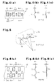
- a first embodiment that embodies the present invention is described with reference to Fig. 1 to Fig. 5 .
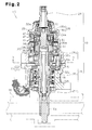
- the present invention is described by defining the upper side and the lower side as shown in Fig. 2 .
- a steering wheel 2 is fixed to a steering shaft 3.
- the steering shaft 3 is joined to a rack shaft 5 by a rack-and-pinion mechanism 4.
- Rotation of the steering shaft 3 according to a steering operation is converted into reciprocating linear movement of the rack shaft 5 by the rack-and-pinion mechanism 4.
- a column shaft 8, an intermediate shaft 9, and a pinion shaft 10 are joined to each other.
- tie rods 11 are joined, respectively. Reciprocating linear movement of the rack shaft 5 according to rotation of the steering shaft 3 is transmitted to knuckles (not illustrated) via the tie rods 11. Accordingly, the turning angle of steered wheels 12, that is, the advancing direction of the vehicle is changed.
- the vehicle steering apparatus 1 is configured as a so-called rack-assist type electric power steering apparatus which moves the rack shaft 5 in an axial direction by using the motor 13.
- the vehicle steering apparatus 1 applies a motor torque as an assist force to a steering system by converting rotation of the motor 13 into reciprocating movement of the rack shaft 5 by a ball screw mechanism 14 and transmitting the same.
- the vehicle steering apparatus 1 includes a variable transmission ratio device 15 that varies a ratio of a turning angle (tire angle) of the steered wheels 12 to the turning angle (steering angle) of the steering wheel 2, that is, a transmission ratio (steering gear ratio).
- the variable transmission ratio device 15 is provided on the pinion shaft 10 constituting the steering shaft 3.
- a rack housing 16 including a pinion housing 17 is fixed.
- the variable transmission ratio device 15 is housed in the pinion housing 17.
- a torque sensor 18 for detecting a steering torque to be used to control the assist force is provided.
- the pinion housing 17 includes a lower housing 21 and an upper housing 22.
- the lower housing 21 is fixed to the upper portion of the rack housing 16 and formed substantially into a cylindrical shape.
- the upper housing 22 is fixed to the upper end of the lower housing 21 and formed substantially into a cylindrical shape.
- the pinion shaft 10 is inserted into the pinion housing 17. At the lower end of the pinion shaft 10, pinion teeth 10a are formed.
- the pinion shaft 10 is supported rotatably in a state where the pinion shaft is meshed with rack teeth (not illustrated) of the rack shaft 5 via the pinion teeth 10a.
- the pinion shaft 10 includes an input shaft 24 and an output shaft 25 including the pinion teeth 10a. As shown in Fig. 1 , into an input shaft 24 joined to the intermediate shaft 9, rotation according to a steering operation is input.
- the variable ratio transmission device 15 includes a wave gear mechanism 26 and a motor 27 that drives the wave gear mechanism 26.
- the wave gear mechanism 26 and the motor 27 are housed in the upper housing 22.
- the wave gear mechanism 26 functions as a differential mechanism interposed between the input shaft 24 and the output shaft 25.
- the input shaft 24 is supported rotatably with respect to the upper end portion 22a of the upper housing 22 via a bearing 31.
- the output shaft 25 is supported rotatably with respect to the lower housing 21 via bearings 32a and 32b.
- the upper end of the output shaft 25 is made to project to the inside of the upper housing 22.
- the output shaft 25 includes a first shaft member 25a that is joined to the wave gear mechanism 26, a second shaft member 25b including the pinion teeth 10a, and a torsion bar 25c that joins the first and second shaft members 25a and 25b.
- the torque sensor 18 measures a torsion angle of the torsion bar 25c to detect a steering torque to be input into the steering system.
- the motor 27 includes a rotor 35 and a stator 36 that generates a rotating magnetic field that rotates the rotor 35.
- the rotor 35 includes a hollow motor shaft 34.
- a motor housing 37 is fixed to the inner peripheral surface of the upper housing 22, a motor housing 37 is fixed.
- the stator 36 is disposed inside the motor housing 37.
- the rotor 35 is supported rotatably with respect to the motor housing 37 via bearings 38a and 38b.
- the upper end of the output shaft 25 is inserted into the inside of the motor shaft 34 and extends to the vicinity of the upper end portion 22a of the upper housing 22.
- the wave gear mechanism 26 is disposed adjacent to the upper side of the motor 27.
- the wave gear mechanism 26 includes a pair of circular splines 41 and 42 disposed coaxially, a tubular flex spline 43, and a wave generator 44.
- the flex spline 43 partially meshes with the circular splines 41 and 42, and is disposed coaxially with the respective circular splines 41 and 42.
- the wave generator 44 rotates the meshing portion of the flex spline 43 according to driving of the motor.
- the number of teeth of the circular spline 41 is different from that of the circular spline 42.
- the flex spline 43 is disposed inside the circular splines 41 and 42 in a state where the flex spline is warped substantially into a oval shape. Therefore, the external teeth of the flex spline 43 are partially meshed with the internal teeth of the circular splines 41 and 42, respectively.
- the output shaft 25 (first shaft member 25a) is joined to the circular spline 42 via a joint member 46.
- the joint member 46 includes a tubular portion 46a fitted to the outer periphery of the output shaft 25 and a flange portion 46b extending radially outward along the lower end of the tubular portion 46a.
- the flange portion 46b is fitted to the inner peripheral surface of the circular spline 42.
- a tubular portion 24a having an inner radius larger than outer radiuses of the circular splines 41 and 42 is formed. Inside the tubular portion 24a, the wave gear mechanism 26 and the joint member 46 are housed.
- the inner peripheral surface of the tubular portion 24a is press-fitted in and fitted to the outer peripheral surface of the circular spline 41.
- the input shaft 24 is joined to the circular spline 41 via the tubular portion 24a.
- the wave generator 44 is disposed inside the flex spline 43.
- the wave generator 44 is joined to the upper end of the motor shaft 34.
- the wave generator 44 rotates the oval shape of the flex spline 43, that is, the meshing portion between the flex spline 43 and the both circular splines 41 and 42 according to driving of the motor 27.
- rotation of the input shaft 24 according to a steering operation is transmitted to the circular spline 41, the flex spline 43, and the circular spline 42 joined to the input shaft 24 in order, and then transmitted to the output shaft 25.
- the wave generator 44 is driven by the motor 27, and the oval shape of the flex spline 43, that is, the meshing portion between the flex spline 43 and the both circular splines 41 and 42 rotates.
- a rotation difference based on the difference in the number of teeth between the both circular splines 41 and 42 is added as rotation based on motor driving to rotation based on a steering operation and transmitted to the output shaft 25. Accordingly, a rotation transmission ratio between the input shaft 24 and the output shaft 25, that is, a transmission ratio between the steering wheel 2 and the steered wheels 12 is changed.
- the variable transmission ratio device 15 includes a locking device 51 below the motor 27.
- the locking device 51 locks the motor shaft 34 so that the motor shaft 34 becomes incapable of rotating with respect to the upper housing 22.
- the upper housing 22 and the lower housing 21 are fixed to the rack housing 16. Therefore, even when the input shaft 24 rotates, the upper housing 22 and the lower housing 21 that are non-rotating members do not rotate. According to actuation of the locking device 51, the transmission ratio can be mechanically fixed as appropriate.
- the locking device 51 includes a lock holder 52 fixed to the motor shaft 34, a lock arm 53 that restrains rotation of the lock holder 52, and a solenoid 54 that drives the lock arm 53.
- the lock holder 52 is formed substantially into a ring shape, and fixed to the motor shaft 34.
- On the outer peripheral surface 52a of the lock holder 52 four engagement grooves 56 are formed at intervals of 90°.
- the respective engagement grooves 56 penetrate the lock holder 52 in the thickness direction of the lock holder 52, and extend in the circumferential direction of the lock holder 52.
- Each engagement groove 56 consists of a shallow groove 56a extending in the circumferential direction and a deep groove 56b provided on one of the end portions of the shallow groove 56a. Between two engagement grooves 56 adjacent to each other, an end wall portion 57 is formed.
- the support shaft 59 is disposed on the radially outer side of the lock holder 52.
- the lock arm 53 is joined turnably with respect to the support shaft 59.
- On the tip end of the lock arm 53 an engagement portion 61 that projects toward the outer peripheral surface 52a of the lock holder 52 is formed.
- To the base end of the lock arm 53 a shaft-shaped plunger 62 is joined. According to driving of the solenoid 54, the plunger 62 is movable in the axial direction thereof.
- the support shaft 59 and the solenoid 54 are fixed onto the motor housing 37 of the motor 27 fixed to the upper housing 22.
- a torsion coil spring 63 is attached.
- the lock arm 53 is energized by an elastic force of the torsion coil spring 63 so as to turn the engagement portion 61 toward the lock holder 52.
- the lock arm 53 is energized by an elastic force of the torsion coil spring 63 so as to turn the engagement portion 61 toward the lock holder 52.
- the locking device 51 further includes a tolerance ring 64 between the motor shaft 34 and the lock holder 52.
- the tolerance ring 64 is illustrated in an exaggerated manner.
- the tolerance ring 64 includes a ring main body 65 formed by curving a band-shaped metal plate substantially in a C-shape. On the ring main body 65, a plurality of spring-like portions 66 elastically deformable in the radial direction are formed.
- the tolerance ring 64 is press-fitted between the motor shaft 34 and the lock holder 52 in a state where the respective spring-like portions 66 are compressed in the radial direction. Therefore, on the tolerance ring 64, frictional resistance is caused by elastic forces of the spring-like portions 66.
- the frictional resistance between the spring-like portions 66 of the tolerance ring 64 and the lock holder 52 restricts the motor shaft 34 and the lock holder 52 from rotating relative to each other.
- the outer peripheral surface of the tolerance ring 64 becomes a slipping surface and allows the motor shaft 34 and the lock holder 52 to rotate relative to each other.
- the tolerance ring 64 functions as a torque limiter.
- the motor shaft 34 corresponds to the first rotating member
- the lock holder 52 corresponds to the second rotating member.
- a maximum torque at which the relative rotation of the motor shaft 34 and the lock holder 52 can be restricted is called a slipping torque.
- the lock arm 53 turns the engagement portion 61 outward in the radial direction of the lock holder 52 against the elastic force of the torsion coil spring 63. Accordingly, the motor shaft 34 becomes rotatable with respect to the upper housing 22, and is brought into an unlocked state. In the unlocked state, rotation based on motor driving is added to the rotation of the input shaft 24 based on a steering operation and transmitted to the output shaft 25.
- the lock arm 53 turns the engagement portion 61 toward the lock holder 52. Then, the engagement portion 61 is inserted into the engagement groove 56 and engages with the end wall portion 57, and accordingly, the lock holder 52 becomes incapable of rotating with respect to the upper housing 22, and is brought into a locked state.
- the locked state even if power supply to the motor 27 is stopped, the motor shaft 34 does not idle with respect to the stator 36, and torque transmission between the input shaft 24 and the output shaft 25 is enabled.
- the locked state due to biting of foreign matter in the wave gear mechanism 26, etc., the input shaft 24 and the output shaft 25 may become incapable of rotating relative to the motor shaft 34. In such a case, when a torque equal to or more than the slipping torque is input, the input shaft 24 and the output shaft 25 rotate together with the motor shaft 34 with respect to the upper housing 22. Accordingly, even in an abnormal state, the steering operation can be continuously performed.
- the spring-like portions 66 of the tolerance ring 64 consist of a plurality of main protrusions 71 and a plurality of sub-protrusions 72.
- the main protrusions 71 are respectively disposed in a compressed state between the motor shaft 34 and the lock holder 52.
- the sub-protrusions 72 are disposed in an uncompressed state.
- the main protrusions 71 and the sub-protrusions 72 protrude radially outward from the ring main body 65.
- the main protrusions 71 and the sub-protrusions 72 are formed substantially into trapezoidal quadrangular pyramids.
- the protruding amount Hm of the main protrusions 71 is larger than the protruding amount Hs of the sub-protrusions 72.
- the length Lm from the center O of the tolerance ring 64 to the top surface 71 a of the main protrusion 71 is larger than the inner radius R of the lock holder 52.
- the main protrusions 71 are brought into contact with the inner peripheral surface of the lock holder 52 and compressed by the motor shaft 34 and the lock holder 52.
- the length Ls from the center O of the tolerance ring 64 to the top surface 72a of the sub-protrusion 72 is smaller than the inner radius R of the lock holder 52. Therefore, the sub-protrusions 72 are not brought into contact with the inner peripheral surface of the lock holder 52 and not compressed.
- the main protrusions 71 and the sub-protrusions 72 are respectively disposed at even angular intervals in an alternate manner in the circumferential direction of the ring main body 65.
- the main protrusions 71 and the sub-protrusions 72 are formed near the center in the axial direction of the ring main body 65.
- variable transmission ratio device 15 in a state where the shaft center of the motor shaft 34 and the shaft center of the lock holder 52 match each other, the frictional resistance caused by the elastic forces of the main protrusions 71 restricts the motor shaft 34 and the lock holder 52 from rotating relative to each other.
- the sub-protrusions 72 near the lock arm 53 to which the impact is applied are compressed by the motor shaft 34 and the lock holder 52. Therefore, in addition to the frictional resistance of the main protrusions 71, the frictional resistance caused by the elastic forces of the sub-protrusions 72 also restricts the motor shaft 34 and the lock holder 52 from rotating relative to each other.
- the first embodiment provides the following operations and effects.
- the main protrusion 71 is respectively formed near each of open ends of the ring main body 65.
- the main protrusions 71 are disposed at a predetermined interval in the axial direction of the ring main body 65.
- the second embodiment provides the following effects in addition to the effects of (1) and (2) described above.
- the main protrusion 71 is respectively formed near each of both open ends of the ring main body 65.
- the main protrusions 71 are disposed at a predetermined interval in the axial direction of the ring main body 65.
- the sub-protrusions 72 are formed substantially into trapezoidal quadrangular pyramids.
- the sub-protrusion 72 extends from the vicinity of one open end to the vicinity of the other open end of the ring main body 65.
- the apex of the main protrusion 71 extends along the axis.
- the sectional shape of the main protrusion 71 orthogonal to the axis is substantially triangular.
- the main protrusions 71 and the sub-protrusions 72 are formed by plastically deforming the ring main body 65 by means of press working. On an inner peripheral surface 65a of the ring main body 65, at positions corresponding to the main protrusions 71 and the sub-protrusions 72, concavities 71 b and 72b are formed, respectively.
- variable transmission ratio device 15 in a case where an abnormality occurs in the wave gear mechanism 26 in a locked state made by the locking device 51, when a torque equal to or more than the slipping torque is input, the inner peripheral surface 65a of the tolerance ring 64 becomes a slipping surface, and the motor shaft 34 and the lock holder 52 are allowed to rotate relative to each other. Thus, even in an abnormal state, a steering operation can be continuously performed.
- the third embodiment provides the following operation and effect in addition to the effects of (1) and (2) of the first embodiment and (3) of the second embodiment.
- the grease 73 is present between the inner peripheral surface 65a of the ring main body 65 and the outer peripheral surface 34a of the motor shaft 34.
- an annular groove 74 is formed at a position opposite to the concavities 72b of the ring main body 65.
- the first to third embodiments may be modified as follows.
Landscapes
- Engineering & Computer Science (AREA)
- General Engineering & Computer Science (AREA)
- Mechanical Engineering (AREA)
- Chemical & Material Sciences (AREA)
- Combustion & Propulsion (AREA)
- Transportation (AREA)
- Power Steering Mechanism (AREA)
Applications Claiming Priority (3)
| Application Number | Priority Date | Filing Date | Title |
|---|---|---|---|
| JP2011048000 | 2011-03-04 | ||
| JP2011182338A JP5866160B2 (ja) | 2011-03-04 | 2011-08-24 | トルクリミッタ及び伝達比可変装置 |
| PCT/JP2012/054375 WO2012121018A1 (ja) | 2011-03-04 | 2012-02-23 | トルクリミッタ、伝達比可変装置及びトレランスリング |
Publications (3)
| Publication Number | Publication Date |
|---|---|
| EP2682623A1 true EP2682623A1 (de) | 2014-01-08 |
| EP2682623A4 EP2682623A4 (de) | 2015-06-24 |
| EP2682623B1 EP2682623B1 (de) | 2018-10-10 |
Family
ID=46797987
Family Applications (1)
| Application Number | Title | Priority Date | Filing Date |
|---|---|---|---|
| EP12754242.1A Not-in-force EP2682623B1 (de) | 2011-03-04 | 2012-02-23 | Drehmomentbegrenzer, vorrichtung mit variablem übersetzungsverhältnis und toleranzring |
Country Status (5)
| Country | Link |
|---|---|
| US (2) | US9109632B2 (de) |
| EP (1) | EP2682623B1 (de) |
| JP (1) | JP5866160B2 (de) |
| CN (1) | CN103403379B (de) |
| WO (1) | WO2012121018A1 (de) |
Cited By (1)
| Publication number | Priority date | Publication date | Assignee | Title |
|---|---|---|---|---|
| DE102022127504A1 (de) * | 2022-10-19 | 2024-04-25 | Schaeffler Technologies AG & Co. KG | Drehmomentübertragungseinrichtung eines Kraftfahrzeugs |
Families Citing this family (21)
| Publication number | Priority date | Publication date | Assignee | Title |
|---|---|---|---|---|
| DE102012219548A1 (de) * | 2012-07-18 | 2014-01-23 | Takata AG | Arretierungseinrichtung zum Arretieren einer bewegbaren Komponente |
| EP2923900B1 (de) * | 2012-11-26 | 2017-05-24 | NSK Ltd. | Lenkvorrichtung |
| US9222521B2 (en) * | 2012-12-16 | 2015-12-29 | Saint-Gobain Performance Plastics Rencol Limited | Torque limiting tolerance ring |
| CN104918839A (zh) * | 2013-01-24 | 2015-09-16 | 丰田自动车株式会社 | 电动动力转向装置 |
| WO2014123166A1 (ja) * | 2013-02-05 | 2014-08-14 | 日本発條株式会社 | トレランスリングおよびハードディスク装置 |
| US10125854B2 (en) | 2013-09-20 | 2018-11-13 | Bair-Ling Technologies, LLC | Torque limiting system |
| CN105874231A (zh) * | 2014-02-20 | 2016-08-17 | 株式会社东乡制作所 | 转矩传递装置用的公差环 |
| CN204419897U (zh) * | 2014-09-23 | 2015-06-24 | 美国圣戈班性能塑料公司 | 具有凹槽的组件 |
| KR101796917B1 (ko) * | 2015-07-03 | 2017-11-13 | (주)로보티즈 | 액추에이터 모듈의 아이들러 혼 착탈 장치 |
| JP6605253B2 (ja) * | 2015-08-07 | 2019-11-13 | 株式会社東郷製作所 | トレランスリング |
| JP6523861B2 (ja) | 2015-08-07 | 2019-06-05 | 株式会社東郷製作所 | 軸継手構造 |
| DE102015113488A1 (de) * | 2015-08-14 | 2017-02-16 | Sami Haddadin | Verbindungsanordnung eines Getriebes in einer Struktur |
| JP6468176B2 (ja) * | 2015-12-10 | 2019-02-13 | トヨタ自動車株式会社 | 車両の動力伝達装置 |
| JP6380361B2 (ja) * | 2015-12-10 | 2018-08-29 | トヨタ自動車株式会社 | 車両の動力伝達装置 |
| JP6341216B2 (ja) | 2016-02-09 | 2018-06-13 | トヨタ自動車株式会社 | 車両の動力伝達装置 |
| CN107640209B (zh) * | 2016-07-22 | 2021-10-26 | 罗伯特·博世汽车转向系统有限责任公司 | 转向管柱 |
| JP6709130B2 (ja) * | 2016-08-24 | 2020-06-10 | 本田技研工業株式会社 | 車両用操舵装置 |
| US11193315B2 (en) | 2016-11-01 | 2021-12-07 | Saint-Gobain Performance Plastics Rencol Limited | Friction brake |
| KR101867277B1 (ko) * | 2017-01-18 | 2018-06-15 | (주)로보티즈 | 반중공형 액추에이터 모듈 |
| JP6957423B2 (ja) * | 2018-08-07 | 2021-11-02 | 株式会社東郷製作所 | トレランスリング |
| WO2021116435A1 (en) | 2019-12-13 | 2021-06-17 | Saint-Gobain Performance Plastics Rencol Limited | Assembly comprising a tolerance ring between two components with desired slipping torque at the surfaces of contact |
Family Cites Families (25)
| Publication number | Priority date | Publication date | Assignee | Title |
|---|---|---|---|---|
| IT984360B (it) * | 1972-03-06 | 1974-11-20 | Star Kugelhalter Gmbh Dt | Elemento di inserto interponibile tra organi di macchine a scopo di collegamento |
| US4286894A (en) * | 1979-03-21 | 1981-09-01 | Roller Bearing Company Of America | Tolerance rings |
| US4376254A (en) * | 1981-06-10 | 1983-03-08 | General Motors Corporation | Annular molded article secured to a shaft |
| JP3411726B2 (ja) | 1995-05-01 | 2003-06-03 | 光洋精工株式会社 | 電動パワーステアリング装置 |
| JP3543041B2 (ja) * | 1996-01-30 | 2004-07-14 | 光洋精工株式会社 | 電動パワーステアリング装置 |
| JP2001159429A (ja) * | 1999-11-30 | 2001-06-12 | Mitsubishi Electric Corp | 電動パワーステアリング装置 |
| JP2002308119A (ja) * | 2001-04-12 | 2002-10-23 | Mitsuba Corp | 電気式動力操舵装置 |
| US20050070365A1 (en) * | 2003-09-30 | 2005-03-31 | Riefe Richard K. | Bushing for telescoping steering column assembly |
| US7252615B2 (en) * | 2004-03-22 | 2007-08-07 | General Motors Corporation | Lubrication system and method for hybrid electro-mechanical planetary transmission components |
| GB0409690D0 (en) * | 2004-04-30 | 2004-06-02 | Rencol Tolerance Rings Ltd | Fastener |
| US7611303B2 (en) * | 2005-06-01 | 2009-11-03 | Intri-Plex Technologies, Inc. | Tolerance ring with high axial static friction |
| GB0511494D0 (en) * | 2005-06-06 | 2005-07-13 | Rencol Tolerance Rings Ltd | Force limiting assembly |
| US7610671B2 (en) * | 2005-10-31 | 2009-11-03 | A.O. Smith Corporation | Method for assembling an electric motor using a slip fit tolerance ring |
| US7819041B2 (en) * | 2005-11-24 | 2010-10-26 | Jtekt Corporation | Transmission ratio variable device and steering gear |
| WO2007125928A1 (ja) * | 2006-04-27 | 2007-11-08 | Nsk Ltd. | 締結具及びステアリング装置 |
| JP4923829B2 (ja) * | 2006-08-03 | 2012-04-25 | 株式会社ジェイテクト | ステアリング装置 |
| US7850389B2 (en) * | 2006-08-15 | 2010-12-14 | Intriplex Technologies, Inc. | Tolerance ring having various end tab designs to prevent interlocking |
| US7580225B2 (en) * | 2006-08-15 | 2009-08-25 | Intri-Plex Technologies, Inc. | Tolerance ring having variable height and/or assymmetrically located bumps |
| US8233242B2 (en) * | 2007-04-24 | 2012-07-31 | Saint-Gobain Performance Plastics Rencol Limited | Tolerance ring with overlapping layers |
| EP1985875B1 (de) | 2007-04-24 | 2013-10-02 | Saint-Gobain Performance Plastics Rencol Limited | Montageanordnung |
| US7905495B2 (en) * | 2007-11-29 | 2011-03-15 | Rolls-Royce Corporation | Circumferential sealing arrangement |
| US8684624B2 (en) * | 2008-07-01 | 2014-04-01 | Saint-Gobain Performance Plastics Rencol Limited | Tolerance ring |
| EP2337962B1 (de) * | 2008-09-10 | 2014-04-16 | Saint-Gobain Performance Plastics Rencol Ltd. | Toleranzring und befestigungsanordnung mit solch einem toleranzring |
| MX2012007091A (es) * | 2009-12-18 | 2012-08-23 | Saint Gobain Performance Plast | Sistema, metodo y aparto para cojinetes y anillos de tolerancia con capas funcionales. |
| US8385024B2 (en) * | 2010-10-07 | 2013-02-26 | IntriPlex Technologies | Tolerance ring with edge bump difference |
-
2011
- 2011-08-24 JP JP2011182338A patent/JP5866160B2/ja not_active Expired - Fee Related
-
2012
- 2012-02-23 US US13/985,653 patent/US9109632B2/en not_active Expired - Fee Related
- 2012-02-23 CN CN201280011092.2A patent/CN103403379B/zh not_active Expired - Fee Related
- 2012-02-23 WO PCT/JP2012/054375 patent/WO2012121018A1/ja not_active Ceased
- 2012-02-23 EP EP12754242.1A patent/EP2682623B1/de not_active Not-in-force
-
2015
- 2015-07-07 US US14/792,988 patent/US9920794B2/en not_active Expired - Fee Related
Cited By (1)
| Publication number | Priority date | Publication date | Assignee | Title |
|---|---|---|---|---|
| DE102022127504A1 (de) * | 2022-10-19 | 2024-04-25 | Schaeffler Technologies AG & Co. KG | Drehmomentübertragungseinrichtung eines Kraftfahrzeugs |
Also Published As
| Publication number | Publication date |
|---|---|
| JP2012197927A (ja) | 2012-10-18 |
| CN103403379B (zh) | 2015-12-02 |
| US9109632B2 (en) | 2015-08-18 |
| US20130324345A1 (en) | 2013-12-05 |
| JP5866160B2 (ja) | 2016-02-17 |
| WO2012121018A1 (ja) | 2012-09-13 |
| EP2682623A4 (de) | 2015-06-24 |
| US20150308511A1 (en) | 2015-10-29 |
| US9920794B2 (en) | 2018-03-20 |
| EP2682623B1 (de) | 2018-10-10 |
| CN103403379A (zh) | 2013-11-20 |
Similar Documents
| Publication | Publication Date | Title |
|---|---|---|
| EP2682623B1 (de) | Drehmomentbegrenzer, vorrichtung mit variablem übersetzungsverhältnis und toleranzring | |
| EP1818242B1 (de) | Elektrische Servolenkung | |
| EP2597014B1 (de) | Elektrisches Servolenksystem | |
| US8434585B2 (en) | Electric power steering system and vehicle steering system | |
| US20170158221A1 (en) | Steering Device | |
| EP2810851A1 (de) | Lenksystem | |
| US8784253B2 (en) | Transmission ratio variable device | |
| US9096258B2 (en) | Gearbox assembly for electric power steering systems | |
| JP2005255121A (ja) | 電動式パワーステアリング装置 | |
| JP2012045978A (ja) | 車両用操舵装置 | |
| JP6396201B2 (ja) | 電動パワーステアリング装置 | |
| US7819041B2 (en) | Transmission ratio variable device and steering gear | |
| JP6305799B2 (ja) | パワーステアリング装置 | |
| JP2019209935A (ja) | 転舵軸支持構造 | |
| JP2014091375A (ja) | 伝達比可変装置 | |
| JP2019107989A (ja) | ステアリング装置 | |
| JP2025015044A (ja) | トルクリミッタ及びステアリング装置 | |
| JP2011240842A (ja) | 伝達比可変装置及び車両用操舵装置 | |
| JP5482551B2 (ja) | 伝達比可変装置及び車両用操舵装置 | |
| JP5056304B2 (ja) | 伝達比可変装置 | |
| JP6940005B2 (ja) | トルク検出装置及びその組立方法、電動式パワーステアリング装置 | |
| JP2010038217A (ja) | ボールねじ装置 | |
| JP2019209855A (ja) | 車両用操舵装置 | |
| JP2014091415A (ja) | 伝達比可変装置 | |
| JP2022121843A (ja) | 中間シャフト及びステアリング装置 |
Legal Events
| Date | Code | Title | Description |
|---|---|---|---|
| PUAI | Public reference made under article 153(3) epc to a published international application that has entered the european phase |
Free format text: ORIGINAL CODE: 0009012 |
|
| 17P | Request for examination filed |
Effective date: 20130829 |
|
| AK | Designated contracting states |
Kind code of ref document: A1 Designated state(s): AL AT BE BG CH CY CZ DE DK EE ES FI FR GB GR HR HU IE IS IT LI LT LU LV MC MK MT NL NO PL PT RO RS SE SI SK SM TR |
|
| DAX | Request for extension of the european patent (deleted) | ||
| RA4 | Supplementary search report drawn up and despatched (corrected) |
Effective date: 20150527 |
|
| RIC1 | Information provided on ipc code assigned before grant |
Ipc: B62D 5/00 20060101ALI20150520BHEP Ipc: F16D 7/02 20060101AFI20150520BHEP Ipc: F16D 1/09 20060101ALI20150520BHEP Ipc: B62D 5/04 20060101ALI20150520BHEP Ipc: F16H 57/04 20100101ALI20150520BHEP |
|
| STAA | Information on the status of an ep patent application or granted ep patent |
Free format text: STATUS: EXAMINATION IS IN PROGRESS |
|
| 17Q | First examination report despatched |
Effective date: 20170208 |
|
| GRAP | Despatch of communication of intention to grant a patent |
Free format text: ORIGINAL CODE: EPIDOSNIGR1 |
|
| STAA | Information on the status of an ep patent application or granted ep patent |
Free format text: STATUS: GRANT OF PATENT IS INTENDED |
|
| INTG | Intention to grant announced |
Effective date: 20180425 |
|
| GRAS | Grant fee paid |
Free format text: ORIGINAL CODE: EPIDOSNIGR3 |
|
| GRAA | (expected) grant |
Free format text: ORIGINAL CODE: 0009210 |
|
| STAA | Information on the status of an ep patent application or granted ep patent |
Free format text: STATUS: THE PATENT HAS BEEN GRANTED |
|
| AK | Designated contracting states |
Kind code of ref document: B1 Designated state(s): AL AT BE BG CH CY CZ DE DK EE ES FI FR GB GR HR HU IE IS IT LI LT LU LV MC MK MT NL NO PL PT RO RS SE SI SK SM TR |
|
| REG | Reference to a national code |
Ref country code: GB Ref legal event code: FG4D |
|
| REG | Reference to a national code |
Ref country code: CH Ref legal event code: EP Ref country code: AT Ref legal event code: REF Ref document number: 1051598 Country of ref document: AT Kind code of ref document: T Effective date: 20181015 |
|
| REG | Reference to a national code |
Ref country code: IE Ref legal event code: FG4D |
|
| REG | Reference to a national code |
Ref country code: DE Ref legal event code: R096 Ref document number: 602012052046 Country of ref document: DE |
|
| REG | Reference to a national code |
Ref country code: NL Ref legal event code: MP Effective date: 20181010 |
|
| REG | Reference to a national code |
Ref country code: LT Ref legal event code: MG4D |
|
| REG | Reference to a national code |
Ref country code: AT Ref legal event code: MK05 Ref document number: 1051598 Country of ref document: AT Kind code of ref document: T Effective date: 20181010 |
|
| PG25 | Lapsed in a contracting state [announced via postgrant information from national office to epo] |
Ref country code: NL Free format text: LAPSE BECAUSE OF FAILURE TO SUBMIT A TRANSLATION OF THE DESCRIPTION OR TO PAY THE FEE WITHIN THE PRESCRIBED TIME-LIMIT Effective date: 20181010 |
|
| PG25 | Lapsed in a contracting state [announced via postgrant information from national office to epo] |
Ref country code: LV Free format text: LAPSE BECAUSE OF FAILURE TO SUBMIT A TRANSLATION OF THE DESCRIPTION OR TO PAY THE FEE WITHIN THE PRESCRIBED TIME-LIMIT Effective date: 20181010 Ref country code: AT Free format text: LAPSE BECAUSE OF FAILURE TO SUBMIT A TRANSLATION OF THE DESCRIPTION OR TO PAY THE FEE WITHIN THE PRESCRIBED TIME-LIMIT Effective date: 20181010 Ref country code: ES Free format text: LAPSE BECAUSE OF FAILURE TO SUBMIT A TRANSLATION OF THE DESCRIPTION OR TO PAY THE FEE WITHIN THE PRESCRIBED TIME-LIMIT Effective date: 20181010 Ref country code: LT Free format text: LAPSE BECAUSE OF FAILURE TO SUBMIT A TRANSLATION OF THE DESCRIPTION OR TO PAY THE FEE WITHIN THE PRESCRIBED TIME-LIMIT Effective date: 20181010 Ref country code: NO Free format text: LAPSE BECAUSE OF FAILURE TO SUBMIT A TRANSLATION OF THE DESCRIPTION OR TO PAY THE FEE WITHIN THE PRESCRIBED TIME-LIMIT Effective date: 20190110 Ref country code: IS Free format text: LAPSE BECAUSE OF FAILURE TO SUBMIT A TRANSLATION OF THE DESCRIPTION OR TO PAY THE FEE WITHIN THE PRESCRIBED TIME-LIMIT Effective date: 20190210 Ref country code: FI Free format text: LAPSE BECAUSE OF FAILURE TO SUBMIT A TRANSLATION OF THE DESCRIPTION OR TO PAY THE FEE WITHIN THE PRESCRIBED TIME-LIMIT Effective date: 20181010 Ref country code: BG Free format text: LAPSE BECAUSE OF FAILURE TO SUBMIT A TRANSLATION OF THE DESCRIPTION OR TO PAY THE FEE WITHIN THE PRESCRIBED TIME-LIMIT Effective date: 20190110 Ref country code: PL Free format text: LAPSE BECAUSE OF FAILURE TO SUBMIT A TRANSLATION OF THE DESCRIPTION OR TO PAY THE FEE WITHIN THE PRESCRIBED TIME-LIMIT Effective date: 20181010 Ref country code: HR Free format text: LAPSE BECAUSE OF FAILURE TO SUBMIT A TRANSLATION OF THE DESCRIPTION OR TO PAY THE FEE WITHIN THE PRESCRIBED TIME-LIMIT Effective date: 20181010 |
|
| PG25 | Lapsed in a contracting state [announced via postgrant information from national office to epo] |
Ref country code: GR Free format text: LAPSE BECAUSE OF FAILURE TO SUBMIT A TRANSLATION OF THE DESCRIPTION OR TO PAY THE FEE WITHIN THE PRESCRIBED TIME-LIMIT Effective date: 20190111 Ref country code: RS Free format text: LAPSE BECAUSE OF FAILURE TO SUBMIT A TRANSLATION OF THE DESCRIPTION OR TO PAY THE FEE WITHIN THE PRESCRIBED TIME-LIMIT Effective date: 20181010 Ref country code: SE Free format text: LAPSE BECAUSE OF FAILURE TO SUBMIT A TRANSLATION OF THE DESCRIPTION OR TO PAY THE FEE WITHIN THE PRESCRIBED TIME-LIMIT Effective date: 20181010 Ref country code: PT Free format text: LAPSE BECAUSE OF FAILURE TO SUBMIT A TRANSLATION OF THE DESCRIPTION OR TO PAY THE FEE WITHIN THE PRESCRIBED TIME-LIMIT Effective date: 20190210 Ref country code: AL Free format text: LAPSE BECAUSE OF FAILURE TO SUBMIT A TRANSLATION OF THE DESCRIPTION OR TO PAY THE FEE WITHIN THE PRESCRIBED TIME-LIMIT Effective date: 20181010 |
|
| REG | Reference to a national code |
Ref country code: DE Ref legal event code: R097 Ref document number: 602012052046 Country of ref document: DE |
|
| PG25 | Lapsed in a contracting state [announced via postgrant information from national office to epo] |
Ref country code: DK Free format text: LAPSE BECAUSE OF FAILURE TO SUBMIT A TRANSLATION OF THE DESCRIPTION OR TO PAY THE FEE WITHIN THE PRESCRIBED TIME-LIMIT Effective date: 20181010 Ref country code: CZ Free format text: LAPSE BECAUSE OF FAILURE TO SUBMIT A TRANSLATION OF THE DESCRIPTION OR TO PAY THE FEE WITHIN THE PRESCRIBED TIME-LIMIT Effective date: 20181010 Ref country code: IT Free format text: LAPSE BECAUSE OF FAILURE TO SUBMIT A TRANSLATION OF THE DESCRIPTION OR TO PAY THE FEE WITHIN THE PRESCRIBED TIME-LIMIT Effective date: 20181010 |
|
| PLBE | No opposition filed within time limit |
Free format text: ORIGINAL CODE: 0009261 |
|
| STAA | Information on the status of an ep patent application or granted ep patent |
Free format text: STATUS: NO OPPOSITION FILED WITHIN TIME LIMIT |
|
| PG25 | Lapsed in a contracting state [announced via postgrant information from national office to epo] |
Ref country code: RO Free format text: LAPSE BECAUSE OF FAILURE TO SUBMIT A TRANSLATION OF THE DESCRIPTION OR TO PAY THE FEE WITHIN THE PRESCRIBED TIME-LIMIT Effective date: 20181010 Ref country code: EE Free format text: LAPSE BECAUSE OF FAILURE TO SUBMIT A TRANSLATION OF THE DESCRIPTION OR TO PAY THE FEE WITHIN THE PRESCRIBED TIME-LIMIT Effective date: 20181010 Ref country code: SM Free format text: LAPSE BECAUSE OF FAILURE TO SUBMIT A TRANSLATION OF THE DESCRIPTION OR TO PAY THE FEE WITHIN THE PRESCRIBED TIME-LIMIT Effective date: 20181010 Ref country code: SK Free format text: LAPSE BECAUSE OF FAILURE TO SUBMIT A TRANSLATION OF THE DESCRIPTION OR TO PAY THE FEE WITHIN THE PRESCRIBED TIME-LIMIT Effective date: 20181010 |
|
| 26N | No opposition filed |
Effective date: 20190711 |
|
| REG | Reference to a national code |
Ref country code: CH Ref legal event code: PL |
|
| GBPC | Gb: european patent ceased through non-payment of renewal fee |
Effective date: 20190223 |
|
| PG25 | Lapsed in a contracting state [announced via postgrant information from national office to epo] |
Ref country code: LU Free format text: LAPSE BECAUSE OF NON-PAYMENT OF DUE FEES Effective date: 20190223 Ref country code: MC Free format text: LAPSE BECAUSE OF FAILURE TO SUBMIT A TRANSLATION OF THE DESCRIPTION OR TO PAY THE FEE WITHIN THE PRESCRIBED TIME-LIMIT Effective date: 20181010 Ref country code: SI Free format text: LAPSE BECAUSE OF FAILURE TO SUBMIT A TRANSLATION OF THE DESCRIPTION OR TO PAY THE FEE WITHIN THE PRESCRIBED TIME-LIMIT Effective date: 20181010 |
|
| REG | Reference to a national code |
Ref country code: BE Ref legal event code: MM Effective date: 20190228 |
|
| REG | Reference to a national code |
Ref country code: IE Ref legal event code: MM4A |
|
| PG25 | Lapsed in a contracting state [announced via postgrant information from national office to epo] |
Ref country code: CH Free format text: LAPSE BECAUSE OF NON-PAYMENT OF DUE FEES Effective date: 20190228 Ref country code: LI Free format text: LAPSE BECAUSE OF NON-PAYMENT OF DUE FEES Effective date: 20190228 |
|
| PG25 | Lapsed in a contracting state [announced via postgrant information from national office to epo] |
Ref country code: IE Free format text: LAPSE BECAUSE OF NON-PAYMENT OF DUE FEES Effective date: 20190223 Ref country code: GB Free format text: LAPSE BECAUSE OF NON-PAYMENT OF DUE FEES Effective date: 20190223 |
|
| PG25 | Lapsed in a contracting state [announced via postgrant information from national office to epo] |
Ref country code: BE Free format text: LAPSE BECAUSE OF NON-PAYMENT OF DUE FEES Effective date: 20190228 |
|
| PG25 | Lapsed in a contracting state [announced via postgrant information from national office to epo] |
Ref country code: TR Free format text: LAPSE BECAUSE OF FAILURE TO SUBMIT A TRANSLATION OF THE DESCRIPTION OR TO PAY THE FEE WITHIN THE PRESCRIBED TIME-LIMIT Effective date: 20181010 |
|
| PGFP | Annual fee paid to national office [announced via postgrant information from national office to epo] |
Ref country code: DE Payment date: 20200211 Year of fee payment: 9 |
|
| PG25 | Lapsed in a contracting state [announced via postgrant information from national office to epo] |
Ref country code: MT Free format text: LAPSE BECAUSE OF NON-PAYMENT OF DUE FEES Effective date: 20190223 |
|
| PGFP | Annual fee paid to national office [announced via postgrant information from national office to epo] |
Ref country code: FR Payment date: 20200113 Year of fee payment: 9 |
|
| PG25 | Lapsed in a contracting state [announced via postgrant information from national office to epo] |
Ref country code: CY Free format text: LAPSE BECAUSE OF FAILURE TO SUBMIT A TRANSLATION OF THE DESCRIPTION OR TO PAY THE FEE WITHIN THE PRESCRIBED TIME-LIMIT Effective date: 20181010 |
|
| PG25 | Lapsed in a contracting state [announced via postgrant information from national office to epo] |
Ref country code: HU Free format text: LAPSE BECAUSE OF FAILURE TO SUBMIT A TRANSLATION OF THE DESCRIPTION OR TO PAY THE FEE WITHIN THE PRESCRIBED TIME-LIMIT; INVALID AB INITIO Effective date: 20120223 |
|
| REG | Reference to a national code |
Ref country code: DE Ref legal event code: R119 Ref document number: 602012052046 Country of ref document: DE |
|
| PG25 | Lapsed in a contracting state [announced via postgrant information from national office to epo] |
Ref country code: FR Free format text: LAPSE BECAUSE OF NON-PAYMENT OF DUE FEES Effective date: 20210228 Ref country code: DE Free format text: LAPSE BECAUSE OF NON-PAYMENT OF DUE FEES Effective date: 20210901 |
|
| PG25 | Lapsed in a contracting state [announced via postgrant information from national office to epo] |
Ref country code: MK Free format text: LAPSE BECAUSE OF FAILURE TO SUBMIT A TRANSLATION OF THE DESCRIPTION OR TO PAY THE FEE WITHIN THE PRESCRIBED TIME-LIMIT Effective date: 20181010 |