EP2682667A2 - Druckgaszylinderpalette - Google Patents
Druckgaszylinderpalette Download PDFInfo
- Publication number
- EP2682667A2 EP2682667A2 EP12179798.9A EP12179798A EP2682667A2 EP 2682667 A2 EP2682667 A2 EP 2682667A2 EP 12179798 A EP12179798 A EP 12179798A EP 2682667 A2 EP2682667 A2 EP 2682667A2
- Authority
- EP
- European Patent Office
- Prior art keywords
- pallet
- cylinders
- roof
- separating plate
- side walls
- Prior art date
- Legal status (The legal status is an assumption and is not a legal conclusion. Google has not performed a legal analysis and makes no representation as to the accuracy of the status listed.)
- Withdrawn
Links
- 210000003141 lower extremity Anatomy 0.000 claims abstract description 5
- 210000001364 upper extremity Anatomy 0.000 claims abstract description 5
- 230000002093 peripheral effect Effects 0.000 claims description 10
- 210000000056 organ Anatomy 0.000 claims description 9
- 229910052751 metal Inorganic materials 0.000 claims description 3
- 239000002184 metal Substances 0.000 claims description 3
- 239000007789 gas Substances 0.000 description 23
- UFHFLCQGNIYNRP-UHFFFAOYSA-N Hydrogen Chemical compound [H][H] UFHFLCQGNIYNRP-UHFFFAOYSA-N 0.000 description 17
- 239000001257 hydrogen Substances 0.000 description 15
- 229910052739 hydrogen Inorganic materials 0.000 description 15
- 238000009434 installation Methods 0.000 description 14
- 239000000446 fuel Substances 0.000 description 13
- 230000036961 partial effect Effects 0.000 description 5
- 210000003739 neck Anatomy 0.000 description 4
- 230000008901 benefit Effects 0.000 description 3
- 230000000694 effects Effects 0.000 description 3
- 238000005516 engineering process Methods 0.000 description 3
- 230000005484 gravity Effects 0.000 description 3
- 238000004378 air conditioning Methods 0.000 description 2
- 238000013459 approach Methods 0.000 description 2
- 230000008859 change Effects 0.000 description 2
- 239000002131 composite material Substances 0.000 description 2
- 150000002431 hydrogen Chemical class 0.000 description 2
- 239000004575 stone Substances 0.000 description 2
- 229910001209 Low-carbon steel Inorganic materials 0.000 description 1
- 229910000831 Steel Inorganic materials 0.000 description 1
- 238000009825 accumulation Methods 0.000 description 1
- 239000004411 aluminium Substances 0.000 description 1
- 229910052782 aluminium Inorganic materials 0.000 description 1
- XAGFODPZIPBFFR-UHFFFAOYSA-N aluminium Chemical compound [Al] XAGFODPZIPBFFR-UHFFFAOYSA-N 0.000 description 1
- 230000000903 blocking effect Effects 0.000 description 1
- 238000004364 calculation method Methods 0.000 description 1
- 230000002860 competitive effect Effects 0.000 description 1
- 239000006185 dispersion Substances 0.000 description 1
- 238000009826 distribution Methods 0.000 description 1
- 238000005265 energy consumption Methods 0.000 description 1
- 230000002708 enhancing effect Effects 0.000 description 1
- 238000002955 isolation Methods 0.000 description 1
- 238000012423 maintenance Methods 0.000 description 1
- 238000004519 manufacturing process Methods 0.000 description 1
- 239000000463 material Substances 0.000 description 1
- 230000007246 mechanism Effects 0.000 description 1
- 238000000034 method Methods 0.000 description 1
- 238000012544 monitoring process Methods 0.000 description 1
- 230000035515 penetration Effects 0.000 description 1
- 230000008569 process Effects 0.000 description 1
- 230000000135 prohibitive effect Effects 0.000 description 1
- 230000001681 protective effect Effects 0.000 description 1
- 230000009467 reduction Effects 0.000 description 1
- 230000002829 reductive effect Effects 0.000 description 1
- 239000002689 soil Substances 0.000 description 1
- 239000010959 steel Substances 0.000 description 1
- 238000003860 storage Methods 0.000 description 1
- 238000013022 venting Methods 0.000 description 1
Images



Classifications
-
- F—MECHANICAL ENGINEERING; LIGHTING; HEATING; WEAPONS; BLASTING
- F17—STORING OR DISTRIBUTING GASES OR LIQUIDS
- F17C—VESSELS FOR CONTAINING OR STORING COMPRESSED, LIQUEFIED OR SOLIDIFIED GASES; FIXED-CAPACITY GAS-HOLDERS; FILLING VESSELS WITH, OR DISCHARGING FROM VESSELS, COMPRESSED, LIQUEFIED, OR SOLIDIFIED GASES
- F17C13/00—Details of vessels or of the filling or discharging of vessels
- F17C13/08—Mounting arrangements for vessels
- F17C13/084—Mounting arrangements for vessels for small-sized storage vessels, e.g. compressed gas cylinders or bottles, disposable gas vessels, vessels adapted for automotive use
-
- F—MECHANICAL ENGINEERING; LIGHTING; HEATING; WEAPONS; BLASTING
- F17—STORING OR DISTRIBUTING GASES OR LIQUIDS
- F17C—VESSELS FOR CONTAINING OR STORING COMPRESSED, LIQUEFIED OR SOLIDIFIED GASES; FIXED-CAPACITY GAS-HOLDERS; FILLING VESSELS WITH, OR DISCHARGING FROM VESSELS, COMPRESSED, LIQUEFIED, OR SOLIDIFIED GASES
- F17C2205/00—Vessel construction, in particular mounting arrangements, attachments or identifications means
- F17C2205/01—Mounting arrangements
- F17C2205/0103—Exterior arrangements
- F17C2205/0107—Frames
-
- F—MECHANICAL ENGINEERING; LIGHTING; HEATING; WEAPONS; BLASTING
- F17—STORING OR DISTRIBUTING GASES OR LIQUIDS
- F17C—VESSELS FOR CONTAINING OR STORING COMPRESSED, LIQUEFIED OR SOLIDIFIED GASES; FIXED-CAPACITY GAS-HOLDERS; FILLING VESSELS WITH, OR DISCHARGING FROM VESSELS, COMPRESSED, LIQUEFIED, OR SOLIDIFIED GASES
- F17C2205/00—Vessel construction, in particular mounting arrangements, attachments or identifications means
- F17C2205/01—Mounting arrangements
- F17C2205/0123—Mounting arrangements characterised by number of vessels
- F17C2205/013—Two or more vessels
- F17C2205/0134—Two or more vessels characterised by the presence of fluid connection between vessels
- F17C2205/0142—Two or more vessels characterised by the presence of fluid connection between vessels bundled in parallel
-
- F—MECHANICAL ENGINEERING; LIGHTING; HEATING; WEAPONS; BLASTING
- F17—STORING OR DISTRIBUTING GASES OR LIQUIDS
- F17C—VESSELS FOR CONTAINING OR STORING COMPRESSED, LIQUEFIED OR SOLIDIFIED GASES; FIXED-CAPACITY GAS-HOLDERS; FILLING VESSELS WITH, OR DISCHARGING FROM VESSELS, COMPRESSED, LIQUEFIED, OR SOLIDIFIED GASES
- F17C2205/00—Vessel construction, in particular mounting arrangements, attachments or identifications means
- F17C2205/01—Mounting arrangements
- F17C2205/0153—Details of mounting arrangements
- F17C2205/0176—Details of mounting arrangements with ventilation
-
- F—MECHANICAL ENGINEERING; LIGHTING; HEATING; WEAPONS; BLASTING
- F17—STORING OR DISTRIBUTING GASES OR LIQUIDS
- F17C—VESSELS FOR CONTAINING OR STORING COMPRESSED, LIQUEFIED OR SOLIDIFIED GASES; FIXED-CAPACITY GAS-HOLDERS; FILLING VESSELS WITH, OR DISCHARGING FROM VESSELS, COMPRESSED, LIQUEFIED, OR SOLIDIFIED GASES
- F17C2205/00—Vessel construction, in particular mounting arrangements, attachments or identifications means
- F17C2205/03—Fluid connections, filters, valves, closure means or other attachments
- F17C2205/0302—Fittings, valves, filters, or components in connection with the gas storage device
- F17C2205/0323—Valves
- F17C2205/0329—Valves manually actuated
-
- F—MECHANICAL ENGINEERING; LIGHTING; HEATING; WEAPONS; BLASTING
- F17—STORING OR DISTRIBUTING GASES OR LIQUIDS
- F17C—VESSELS FOR CONTAINING OR STORING COMPRESSED, LIQUEFIED OR SOLIDIFIED GASES; FIXED-CAPACITY GAS-HOLDERS; FILLING VESSELS WITH, OR DISCHARGING FROM VESSELS, COMPRESSED, LIQUEFIED, OR SOLIDIFIED GASES
- F17C2221/00—Handled fluid, in particular type of fluid
- F17C2221/01—Pure fluids
- F17C2221/012—Hydrogen
-
- F—MECHANICAL ENGINEERING; LIGHTING; HEATING; WEAPONS; BLASTING
- F17—STORING OR DISTRIBUTING GASES OR LIQUIDS
- F17C—VESSELS FOR CONTAINING OR STORING COMPRESSED, LIQUEFIED OR SOLIDIFIED GASES; FIXED-CAPACITY GAS-HOLDERS; FILLING VESSELS WITH, OR DISCHARGING FROM VESSELS, COMPRESSED, LIQUEFIED, OR SOLIDIFIED GASES
- F17C2223/00—Handled fluid before transfer, i.e. state of fluid when stored in the vessel or before transfer from the vessel
- F17C2223/01—Handled fluid before transfer, i.e. state of fluid when stored in the vessel or before transfer from the vessel characterised by the phase
- F17C2223/0107—Single phase
- F17C2223/0123—Single phase gaseous, e.g. CNG, GNC
-
- F—MECHANICAL ENGINEERING; LIGHTING; HEATING; WEAPONS; BLASTING
- F17—STORING OR DISTRIBUTING GASES OR LIQUIDS
- F17C—VESSELS FOR CONTAINING OR STORING COMPRESSED, LIQUEFIED OR SOLIDIFIED GASES; FIXED-CAPACITY GAS-HOLDERS; FILLING VESSELS WITH, OR DISCHARGING FROM VESSELS, COMPRESSED, LIQUEFIED, OR SOLIDIFIED GASES
- F17C2223/00—Handled fluid before transfer, i.e. state of fluid when stored in the vessel or before transfer from the vessel
- F17C2223/03—Handled fluid before transfer, i.e. state of fluid when stored in the vessel or before transfer from the vessel characterised by the pressure level
- F17C2223/035—High pressure (>10 bar)
-
- F—MECHANICAL ENGINEERING; LIGHTING; HEATING; WEAPONS; BLASTING
- F17—STORING OR DISTRIBUTING GASES OR LIQUIDS
- F17C—VESSELS FOR CONTAINING OR STORING COMPRESSED, LIQUEFIED OR SOLIDIFIED GASES; FIXED-CAPACITY GAS-HOLDERS; FILLING VESSELS WITH, OR DISCHARGING FROM VESSELS, COMPRESSED, LIQUEFIED, OR SOLIDIFIED GASES
- F17C2270/00—Applications
- F17C2270/05—Applications for industrial use
-
- Y—GENERAL TAGGING OF NEW TECHNOLOGICAL DEVELOPMENTS; GENERAL TAGGING OF CROSS-SECTIONAL TECHNOLOGIES SPANNING OVER SEVERAL SECTIONS OF THE IPC; TECHNICAL SUBJECTS COVERED BY FORMER USPC CROSS-REFERENCE ART COLLECTIONS [XRACs] AND DIGESTS
- Y02—TECHNOLOGIES OR APPLICATIONS FOR MITIGATION OR ADAPTATION AGAINST CLIMATE CHANGE
- Y02E—REDUCTION OF GREENHOUSE GAS [GHG] EMISSIONS, RELATED TO ENERGY GENERATION, TRANSMISSION OR DISTRIBUTION
- Y02E60/00—Enabling technologies; Technologies with a potential or indirect contribution to GHG emissions mitigation
- Y02E60/30—Hydrogen technology
- Y02E60/32—Hydrogen storage
Definitions
- the invention concerns a pallet for pressurized gas cylinders.
- the invention relates more particularly to a pallet for transporting a group of pressurized gas cylinders comprising a supporting base, four side walls and a roof defining an enclosure around the cylinders.
- telecommunication sites are generally buffered by batteries and Diesel generators to maintain the quality of services provided to mobile users of telecommunication networks.
- the batteries take over until the generator starts for providing a continuous power supply. If the generator also faces a problem, the remaining power left in the batteries is used to power the main utilities until the intervention of a site technician or network feedback.
- a first type "Indoor” or “ID sites” has its equipments installed in a shelter protected from weather and external attacks. These shelters are equipped with air conditioners to keep inside a controlled temperature ensuring proper functioning and longevity to the equipments.
- the standard air conditioners are powered by alternating current and, when the main power grid fails, air conditioning unit stops. Air conditioning restarts when the diesel generator starts up.
- the battery provides continuous supply to the telecom equipments till the period Diesel generator starts in operation.
- the second type "Outdoor' or 'OD sites' has its equipment installed outdoors or in ventilated cabinets. They have the latest equipments, including an extended temperature range that avoids the use of air conditioners.
- the fuel cells are basically fed with hydrogen gas as a feedstock with authorized numbers of hydrogen (H2) cylinders assembled in sixteen and eight cylinders combination which is called a hydrogen pallet.
- H2 authorized numbers of hydrogen
- a maximum number of twenty five hydrogen gas cylinders can be stored at a single site. This limit may vary from one country to another one.
- Typical fuel cell installations include a fuel cell housed in a cabinet, two or more hydrogen pallets, a gas regulation and automatic changer-over device enabling to distribute the hydrogen flow from its storage pressure into the cylinders down to the pressure and flow required by the fuel cell.
- the installations comprise also safety devices including a vent mast to collect and release hydrogen leaks and venting at a height defined to avoid any exposure of people and equipment in the vicinity of the installation, a protection enclosure consisting in, generally, a metallic mesh and installed to avoid people to penetrate the enclosure.
- a typical Diesel generator has a reduced footprint.
- Typical installations comprise two pallets of eight to sixteen hydrogen cylinders pressurized up to 200bar enclosed in a protective enclosure and placed on a supporting structure.
- each wall comprises an full structure extending from a first upper extremity adjacent to the roof to a second lower extremity situated above the supporting base so that the enclosure is opened at the bottom of the cylinders, the roof comprising a mesh like structure, the pallet comprising a common tap connected to a conduit selectively connected to the cylinders, one of the side walls comprising an aperture giving access to the common tap, the supporting base and the upper part of the pallet situated underneath the roof comprising each several openings for receiving the tines of a fork truck or pallet loader/unloader.
- embodiments might comprise one or more of the following features:
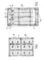
- the pallet shown at the figures comprises, at its bottom, a supporting base 9.
- the pallet comprises four side walls 2 extending from the base 9 to a closing upper roof 1.
- the base 9, walls 2 and roof 1 define a closed volume around the cylinders 18.
- the pallet contains six pairs of cylinders having a volume of fifty liters each.
- similar concept including all the claimed features is suitable for pallets which number and size of cylinders is adjusted to respect the regulations in force in the countries. It is also compatible with any type of cylinders steel aluminium, composite, whatever the cylinders pressure.
- Each wall 2 comprises a full structure extending from a first upper extremity adjacent to the roof 1 to a second lower extremity situated above the supporting base 9. This means that the walls 2 make the enclosure opened at the bottom of the cylinders 18.
- the height opening at the bottom of the side walls 2 is comprised between 5cm and 20cm.
- the side walls 2 are preferably made of mild steel metal sheet panel or any other appropriate material and may have a thickness between 0,5mm and 2.5mm and preferably about 1,6mm.
- This fully closed structure at the side walls 2 avoids any direct impact of jet fire to any personnel in case of any leak from the cylinder valve manifold.
- the side walls 2 are opened at its bottom to provide proper air circulation through the enclosure and avoid any accumulation of gas in case of unforeseen leak in the installation.
- the opening height can be based on calculation for hydrogen leak dispersion for different scenarios and can be approximately about five to twenty centimeters in lateral dimension.
- the roof 1 comprises a mesh like structure.
- the roof is made of wire netting comprising openings each having dimensions between 0,002m 2 and 0,200m 2 and preferably between 0,005m 2 and 0,150m 2 .
- This roof structure prevents any object like a big stone from falling on the cylinder valve manifold situated underneath and is helpful in avoiding damage to any part of the cylinder valve manifold system which otherwise creates a leak on the system.
- the mesh like structure (for example. 100 mm X 100 mm) at the top of pallet is also helpful in blocking possible burning fire crackers to have a direct impact with the cylinder valve manifold and avoids the dangerous situation in case of any gas leak.
- the lower and upper parts of the pallet comprises each several openings 10 for receiving the tines of a fork truck or pallet loader/unloader.
- the upper openings are situated under the roof 1 and the lower openings are situated between the base supporting the cylinders and the lower extremity of the pallet lying on the soil.
- the openings upper and lower openings 10 can be oriented in the sale direction (that is to say parallel to the same side walls 2).
- the fork openings at the top of the pallet permit the lifting from the top by a tractor/forklift. This increases the stability during transportation of the pallet to and from the truck to the site by improving the point of center of gravity making it closer to the center of gravity of the forklift machine.
- the pallet might comprise mobile flaps 51 for selectively closing each upper opening 10 for receiving the tines 50 of a fork truck or pallet loader/unloader.
- the flaps 51 might be installed at the top of the upper panels 30 by means of a hinge 52 and urged to a closing position ( figure 9 ) via a spring 53.
- Each flap 51 is articulated on a hinge 52 so that the entrance of the tines 50 of a fork truck or pallet loader/unloader into the openings 10 pushes the flaps 51 toward their open position against the return organ 53 effort.
- the flaps 51 rotate downwardly.
- the opposite opening (on the opposite face of the pallet) might also comprise a flap 51.
- the two opposite flaps 51 are hinged and mechanically linked via a connecting rod 54 so that the opening on one side forces the opening o the other side (see figure 10 ).
- the pallet comprises a common tap 4 connected to a conduit 14 selectively connected to the cylinders 18.
- One of the side walls 2 comprises an aperture 3 giving access to the common tap 4.
- This cut out aperture 3 (for example having dimensions between 150 and 200 mm) is on a front wall 2 and provides hand access for the valve opening-closing and its maintenance.
- the aperture 3 is preferably covered during operation.
- This structure provides a protection from human/physical approach to access the cylinder manifold assembly and also provide a secured connection between the pallet and gas distribution at site.
- all the dimensions of the pallet are based on cylinder 18 manufacturer dimensions, valve and manifold dimension and the overall arrangement of all equipments and its parts in the structural frame.
- the pallet comprises also connecting points 8 for hooks 88 selectively attachable to distinct base for providing a locking arrangement in case of its sudden unloading from the site by the tractor when the pallet are in operation to supply gas to a receiver (for example a fuel cell system).
- a receiver for example a fuel cell system
- the pallet includes preferably a separating plate 20 situated inside the enclosure.
- the separating plate 20 is perpendicular to the side walls 2 and comprises several holes 21 for receiving respectively the upper part of the cylinders 18.
- the necks 23 of cylinders are fastened into the respective holes 21 of the separating plate 1.
- each neck 23 of cylinders might be fastened into the respective hole 21 by means a threaded nut 24.
- a space is provided between at least part of the peripheral edge 22 of the separating plate 20 and the walls 2. In this manner the separating plate 20 prevents an upper gas leak to mitigate downward in the enclosure.
- the separating plate 20 permits to release a gas leak at the bottom to the top via the space between the separating plate 20 and the walls 2.
- the peripheral edge 22 of the separating plate 20 is curved or bent upwardly as shown in figures 4 and 6 .
- the surface of the walls 2 facing the peripheral edge 22 of the separating plate 1 might be also curved or bent so that it cooperates with the peripheral edge 22 of the separating plate 20 for defining a guiding divergent path for the gas from the bottom to the top. That is to say the gas path forces the gas G coming from the bottom and central area of the enclosure to flow toward the walls 2.
- the same architecture prevents an upper gas leak to flow downwards. This is illustrated in figure 6 , the flows of gas leaks being represented with dotted arrows.
- the separating plate 20 is slipped on the upper extremity of the cylinders by means of the holes 21.
- the cylinders 18 are kept separate from each other with a distance between zero and one cm.
- This function of plate 20 is particularly profitable when cylinders 18 are of composite type, for preventing a contact between the cylinders.
- the side walls 2 might be made of two separate panels 40, 30, for example an upper panel 30 and a lower panel 40.
- the pallet preferably comprises a frame skeleton structure made of bars 40.
- the upper panels 30 might be secured to the bar 40 by means of attaching organs 130 such as threaded bolts screwed into threaded holes the bars 40.
- the bottom edge of upper panels 30 are preferably received into supporting slits 41 located at upper edge of respective bottom panels 40 (for example the supporting slit is a kind of bayonet structure welded .on the lower plate 40).
- the lower panels 40 might also be secured to the bars frame by means of threaded bolts 130 screwed into threaded holes the bars.
- the roof plate 1 may be also used as a structural element to fasten the cylinders into the chassis.
- This pallet structure can be made standard and features several advantages.
- the structure offers a system which have a less chance of leak due to valve failure and assembly failure at the connection points by providing only a single valve assembly to take the pack offline and inline.
- the pallet provides a faster deployment to the site operation with a single valve assembly instead of large number of valves in the existing systems.
- the standardization of the pallet is helpful in achieving in rapid deployment of fuel cells to replace Diesel generators at telecom sites by bringing standard supporting frames to support their weights into the site.
- the standardization of the pallets is helpful in analyzing and monitoring the site consumption data which yields to effective utilization of the gas and reduction in operating cost of pallet change over at site.
- the new pallet doesn't require any additional installation nor extended safety area and therefore it reduces significantly the overall footprint of the installation.
- the new pallet allows varying easily the quantity of H2 stored on site to fit with the customer requirements.
- the invention serves the ultimate objective for any big project for rapid deployment of large number of sites within a stipulated short period of time by providing safe and standardized solution in addition to abiding with the local rules and regulations. It also brings a competitive advantage to the fuel cell technology by reducing significantly the footprint of the installation and by enhancing the safety.
Landscapes
- Engineering & Computer Science (AREA)
- Mechanical Engineering (AREA)
- General Engineering & Computer Science (AREA)
- Filling Or Discharging Of Gas Storage Vessels (AREA)
Applications Claiming Priority (1)
| Application Number | Priority Date | Filing Date | Title |
|---|---|---|---|
| IN2079DE2012 | 2012-07-04 |
Publications (2)
| Publication Number | Publication Date |
|---|---|
| EP2682667A2 true EP2682667A2 (de) | 2014-01-08 |
| EP2682667A3 EP2682667A3 (de) | 2018-03-21 |
Family
ID=46799031
Family Applications (1)
| Application Number | Title | Priority Date | Filing Date |
|---|---|---|---|
| EP12179798.9A Withdrawn EP2682667A3 (de) | 2012-07-04 | 2012-08-09 | Druckgaszylinderpalette |
Country Status (1)
| Country | Link |
|---|---|
| EP (1) | EP2682667A3 (de) |
Cited By (16)
| Publication number | Priority date | Publication date | Assignee | Title |
|---|---|---|---|---|
| CN105972429A (zh) * | 2016-06-27 | 2016-09-28 | 河南平高电气股份有限公司 | 一种六氟化硫气瓶架及使用该气瓶架的充气装置 |
| EP3139080A1 (de) * | 2015-09-04 | 2017-03-08 | L'air Liquide, Societe Anonyme Pour L'etude Et L'exploitation Des Procedes Georges Claude | Gaszylinder und bündel von gasflaschen mit winkel indizierung |
| CN108240553A (zh) * | 2017-11-07 | 2018-07-03 | 苏州市凯利勋实验室设备有限公司 | 一种具备自动报警排气功能的外部可视气瓶柜 |
| GB2561808A (en) * | 2017-01-13 | 2018-10-31 | Linde Ag | Pressure vessel transportation apparatus and method of transporting a pressure vessel |
| US20190031498A1 (en) * | 2015-01-28 | 2019-01-31 | Fuelie Systems, Inc. | Portable Fuel Storage Device |
| US10458599B2 (en) * | 2015-09-04 | 2019-10-29 | L'Air Liquide, Société Anonyme pour l'Etude et l'Exploitation des Procédés Georges Claude | Storage box for bottles of pressurized fluid and associated storage frame |
| EP3438021A4 (de) * | 2016-03-30 | 2019-12-11 | Sorokin, Konstantin Vladimirovich | Transport- und lagerbehälter für zylinder und verfahren zur platzierung von zylindern in einem behälter |
| IT202000007096A1 (it) * | 2020-04-03 | 2021-10-03 | Fulvio Parisi | Apparato di sicurezza per la movimentazione di una pluralità di bom-bole di gas in pressione tra loro pneumaticamente collegate, cosid-detto “pacco bombole” |
| EP3992521A1 (de) * | 2020-10-30 | 2022-05-04 | SOL S.p.A. | Rahmenvorrichtung für mehrere gasbehälter |
| FR3120681A1 (fr) * | 2021-03-10 | 2022-09-16 | Henri Becu | Cadre de stockage et/ou de transport pour bouteilles de fluide sous pression |
| CN115325443A (zh) * | 2021-04-23 | 2022-11-11 | 佛吉亚排气系统有限公司 | 包括通过导轨连接的至少两个缸体的加压气体储罐 |
| US11840444B2 (en) | 2018-03-16 | 2023-12-12 | Fuelie Systems, Inc. | Fuel storage and dispensing device |
| US12097537B2 (en) | 2021-04-23 | 2024-09-24 | Vitalis Extraction Technology Inc. | Solvent containment and process interlocking system |
| WO2024196347A1 (en) * | 2023-03-17 | 2024-09-26 | Steelhead Composites, Inc. | Modular pressure vessel mounting apparatus |
| US12311830B1 (en) * | 2024-07-18 | 2025-05-27 | AIT Worldwide Logistics, Inc. | Bulkhead for trailers and shipping containers |
| EP3885636B1 (de) * | 2020-03-26 | 2025-06-18 | SOL S.p.A. | Vorrichtung für die zufuhr eines gases mit einer vielzahl von gasbehältern |
Family Cites Families (4)
| Publication number | Priority date | Publication date | Assignee | Title |
|---|---|---|---|---|
| GB2007348A (en) * | 1977-11-01 | 1979-05-16 | Unitor Ships Service As | Transport module for gas cylinders |
| US20050181244A1 (en) * | 2004-02-12 | 2005-08-18 | Proton Energy Systems, Inc. | Regenerative fuel cell system and method of operation thereof |
| FR2873666B1 (fr) * | 2004-07-29 | 2008-07-18 | Butagaz Snc | Procede et dispositifs de manutention et de distribution de bouteilles de gaz de petrole liquefie |
| US8016300B2 (en) * | 2007-10-01 | 2011-09-13 | Cramer Decker Industries | Mobile cart having a retractable-wheel base system |
-
2012
- 2012-08-09 EP EP12179798.9A patent/EP2682667A3/de not_active Withdrawn
Non-Patent Citations (1)
| Title |
|---|
| None |
Cited By (21)
| Publication number | Priority date | Publication date | Assignee | Title |
|---|---|---|---|---|
| US20190031498A1 (en) * | 2015-01-28 | 2019-01-31 | Fuelie Systems, Inc. | Portable Fuel Storage Device |
| US10683199B2 (en) * | 2015-01-28 | 2020-06-16 | Fuelie Systems, Inc. | Portable fuel storage device |
| EP3139080A1 (de) * | 2015-09-04 | 2017-03-08 | L'air Liquide, Societe Anonyme Pour L'etude Et L'exploitation Des Procedes Georges Claude | Gaszylinder und bündel von gasflaschen mit winkel indizierung |
| US10458599B2 (en) * | 2015-09-04 | 2019-10-29 | L'Air Liquide, Société Anonyme pour l'Etude et l'Exploitation des Procédés Georges Claude | Storage box for bottles of pressurized fluid and associated storage frame |
| EP3438021A4 (de) * | 2016-03-30 | 2019-12-11 | Sorokin, Konstantin Vladimirovich | Transport- und lagerbehälter für zylinder und verfahren zur platzierung von zylindern in einem behälter |
| CN105972429B (zh) * | 2016-06-27 | 2019-03-12 | 河南平高电气股份有限公司 | 一种六氟化硫气瓶架及使用该气瓶架的充气装置 |
| CN105972429A (zh) * | 2016-06-27 | 2016-09-28 | 河南平高电气股份有限公司 | 一种六氟化硫气瓶架及使用该气瓶架的充气装置 |
| GB2561808A (en) * | 2017-01-13 | 2018-10-31 | Linde Ag | Pressure vessel transportation apparatus and method of transporting a pressure vessel |
| CN108240553A (zh) * | 2017-11-07 | 2018-07-03 | 苏州市凯利勋实验室设备有限公司 | 一种具备自动报警排气功能的外部可视气瓶柜 |
| US11840444B2 (en) | 2018-03-16 | 2023-12-12 | Fuelie Systems, Inc. | Fuel storage and dispensing device |
| EP3885636B1 (de) * | 2020-03-26 | 2025-06-18 | SOL S.p.A. | Vorrichtung für die zufuhr eines gases mit einer vielzahl von gasbehältern |
| WO2021199014A1 (en) * | 2020-04-03 | 2021-10-07 | Parisi Fulvio | Safety apparatus for the movement of a plurality of pneumatically interconnected gas bottles under pressure |
| US12146616B2 (en) | 2020-04-03 | 2024-11-19 | Fulvio PARISI | Safety apparatus for the movement of a plurality of pneumatically interconnected gas bottles under pressure |
| IT202000007096A1 (it) * | 2020-04-03 | 2021-10-03 | Fulvio Parisi | Apparato di sicurezza per la movimentazione di una pluralità di bom-bole di gas in pressione tra loro pneumaticamente collegate, cosid-detto “pacco bombole” |
| EP3992521A1 (de) * | 2020-10-30 | 2022-05-04 | SOL S.p.A. | Rahmenvorrichtung für mehrere gasbehälter |
| FR3120681A1 (fr) * | 2021-03-10 | 2022-09-16 | Henri Becu | Cadre de stockage et/ou de transport pour bouteilles de fluide sous pression |
| CN115325443A (zh) * | 2021-04-23 | 2022-11-11 | 佛吉亚排气系统有限公司 | 包括通过导轨连接的至少两个缸体的加压气体储罐 |
| CN115325443B (zh) * | 2021-04-23 | 2024-06-11 | 佛吉亚排气系统有限公司 | 包括通过导轨连接的至少两个缸体的加压气体储罐 |
| US12097537B2 (en) | 2021-04-23 | 2024-09-24 | Vitalis Extraction Technology Inc. | Solvent containment and process interlocking system |
| WO2024196347A1 (en) * | 2023-03-17 | 2024-09-26 | Steelhead Composites, Inc. | Modular pressure vessel mounting apparatus |
| US12311830B1 (en) * | 2024-07-18 | 2025-05-27 | AIT Worldwide Logistics, Inc. | Bulkhead for trailers and shipping containers |
Also Published As
| Publication number | Publication date |
|---|---|
| EP2682667A3 (de) | 2018-03-21 |
Similar Documents
| Publication | Publication Date | Title |
|---|---|---|
| EP2682667A2 (de) | Druckgaszylinderpalette | |
| DK2729330T3 (en) | MOBILE FUEL DISTRIBUTION STATION | |
| JP5789048B2 (ja) | 移動式の燃料供給ステーション | |
| JP5767405B2 (ja) | 環境に配慮した移動式の燃料供給ステーションを構築する方法 | |
| CN108597633B (zh) | 乏燃料的屏蔽转运方法及设备 | |
| US20030026376A1 (en) | Integrated head assembly for a nuclear reactor | |
| US20230332746A1 (en) | Portable Refueling Device | |
| CA2113399C (en) | Remote fuel station | |
| US20240035298A1 (en) | Platform for space-saving configuration of an energy conversion installation, and energy conversion installation | |
| US20100264669A1 (en) | Generator frame with grappling attachment feature and theft deterring weight receptacle | |
| EP2682668A2 (de) | Vorrichtung zur Abgabe von Druckgas und Anlage zur Herstellung und Versorgung von Strom mit einer solchen Vorrichtung | |
| EP0650436B1 (de) | Versenkbare und versteckbare kraftstoffabgabevorrichtung | |
| CN213667642U (zh) | 锤击桩打桩机用手动控制灭火装置 | |
| RU101136U1 (ru) | Клапан дыхательный | |
| CN223267949U (zh) | 锁销站及锁销装卸系统 | |
| EP2654117A1 (de) | Installation zur Erzeugung und Speisung von Elektrizität mit einer Brennstoffzelle | |
| CN210391537U (zh) | 一种球载机组 | |
| CN219759207U (zh) | 一种带防护网的掀盖式人孔保护罩及配置槽 | |
| CN121894366A (zh) | 一种立式推进剂贮罐的运输装置 | |
| CN220077389U (zh) | 一种防爆覆土储罐及其泄压装置 | |
| SK289182B6 (sk) | Premiestniteľná stanica na čerpanie tekutín | |
| RU2575764C2 (ru) | Мобильная топливораздаточная станция | |
| CN208257180U (zh) | 一种具有防盗功能的箱式变电站 | |
| KR20240161746A (ko) | 하우징 적층형 에너지 저장장치 | |
| CZ33717U1 (cs) | Stanice pro čerpání tekutin |
Legal Events
| Date | Code | Title | Description |
|---|---|---|---|
| PUAI | Public reference made under article 153(3) epc to a published international application that has entered the european phase |
Free format text: ORIGINAL CODE: 0009012 |
|
| AK | Designated contracting states |
Kind code of ref document: A2 Designated state(s): AL AT BE BG CH CY CZ DE DK EE ES FI FR GB GR HR HU IE IS IT LI LT LU LV MC MK MT NL NO PL PT RO RS SE SI SK SM TR |
|
| AX | Request for extension of the european patent |
Extension state: BA ME |
|
| PUAL | Search report despatched |
Free format text: ORIGINAL CODE: 0009013 |
|
| AK | Designated contracting states |
Kind code of ref document: A3 Designated state(s): AL AT BE BG CH CY CZ DE DK EE ES FI FR GB GR HR HU IE IS IT LI LT LU LV MC MK MT NL NO PL PT RO RS SE SI SK SM TR |
|
| AX | Request for extension of the european patent |
Extension state: BA ME |
|
| RIC1 | Information provided on ipc code assigned before grant |
Ipc: F17C 13/08 20060101AFI20180212BHEP |
|
| STAA | Information on the status of an ep patent application or granted ep patent |
Free format text: STATUS: THE APPLICATION HAS BEEN WITHDRAWN |
|
| 18W | Application withdrawn |
Effective date: 20180920 |