EP2682674A2 - Procédé de fonctionnement d'un foyer et foyer - Google Patents
Procédé de fonctionnement d'un foyer et foyer Download PDFInfo
- Publication number
- EP2682674A2 EP2682674A2 EP13173567.2A EP13173567A EP2682674A2 EP 2682674 A2 EP2682674 A2 EP 2682674A2 EP 13173567 A EP13173567 A EP 13173567A EP 2682674 A2 EP2682674 A2 EP 2682674A2
- Authority
- EP
- European Patent Office
- Prior art keywords
- alarm
- flame detector
- fuel
- burner
- wood
- Prior art date
- Legal status (The legal status is an assumption and is not a legal conclusion. Google has not performed a legal analysis and makes no representation as to the accuracy of the status listed.)
- Granted
Links
Images


Classifications
-
- F—MECHANICAL ENGINEERING; LIGHTING; HEATING; WEAPONS; BLASTING
- F23—COMBUSTION APPARATUS; COMBUSTION PROCESSES
- F23B—METHODS OR APPARATUS FOR COMBUSTION USING ONLY SOLID FUEL
- F23B60/00—Combustion apparatus in which the fuel burns essentially without moving
- F23B60/02—Combustion apparatus in which the fuel burns essentially without moving with combustion air supplied through a grate
-
- F—MECHANICAL ENGINEERING; LIGHTING; HEATING; WEAPONS; BLASTING
- F23—COMBUSTION APPARATUS; COMBUSTION PROCESSES
- F23N—REGULATING OR CONTROLLING COMBUSTION
- F23N5/00—Systems for controlling combustion
- F23N5/02—Systems for controlling combustion using devices responsive to thermal changes or to thermal expansion of a medium
- F23N5/022—Systems for controlling combustion using devices responsive to thermal changes or to thermal expansion of a medium using electronic means
-
- F—MECHANICAL ENGINEERING; LIGHTING; HEATING; WEAPONS; BLASTING
- F23—COMBUSTION APPARATUS; COMBUSTION PROCESSES
- F23N—REGULATING OR CONTROLLING COMBUSTION
- F23N5/00—Systems for controlling combustion
- F23N5/02—Systems for controlling combustion using devices responsive to thermal changes or to thermal expansion of a medium
- F23N5/08—Systems for controlling combustion using devices responsive to thermal changes or to thermal expansion of a medium using light-sensitive elements
- F23N5/082—Systems for controlling combustion using devices responsive to thermal changes or to thermal expansion of a medium using light-sensitive elements using electronic means
-
- F—MECHANICAL ENGINEERING; LIGHTING; HEATING; WEAPONS; BLASTING
- F23—COMBUSTION APPARATUS; COMBUSTION PROCESSES
- F23N—REGULATING OR CONTROLLING COMBUSTION
- F23N5/00—Systems for controlling combustion
- F23N5/20—Systems for controlling combustion with a time program acting through electrical means, e.g. using time-delay relays
- F23N5/203—Systems for controlling combustion with a time program acting through electrical means, e.g. using time-delay relays using electronic means
-
- F—MECHANICAL ENGINEERING; LIGHTING; HEATING; WEAPONS; BLASTING
- F23—COMBUSTION APPARATUS; COMBUSTION PROCESSES
- F23N—REGULATING OR CONTROLLING COMBUSTION
- F23N5/00—Systems for controlling combustion
- F23N5/24—Preventing development of abnormal or undesired conditions, i.e. safety arrangements
- F23N5/242—Preventing development of abnormal or undesired conditions, i.e. safety arrangements using electronic means
-
- F—MECHANICAL ENGINEERING; LIGHTING; HEATING; WEAPONS; BLASTING
- F24—HEATING; RANGES; VENTILATING
- F24B—DOMESTIC STOVES OR RANGES FOR SOLID FUELS; IMPLEMENTS FOR USE IN CONNECTION WITH STOVES OR RANGES
- F24B1/00—Stoves or ranges
- F24B1/18—Stoves with open fires, e.g. fireplaces
- F24B1/185—Stoves with open fires, e.g. fireplaces with air-handling means, heat exchange means, or additional provisions for convection heating ; Controlling combustion
- F24B1/187—Condition responsive controls for regulating combustion
-
- F—MECHANICAL ENGINEERING; LIGHTING; HEATING; WEAPONS; BLASTING
- F23—COMBUSTION APPARATUS; COMBUSTION PROCESSES
- F23N—REGULATING OR CONTROLLING COMBUSTION
- F23N2223/00—Signal processing; Details thereof
- F23N2223/38—Remote control
-
- F—MECHANICAL ENGINEERING; LIGHTING; HEATING; WEAPONS; BLASTING
- F23—COMBUSTION APPARATUS; COMBUSTION PROCESSES
- F23N—REGULATING OR CONTROLLING COMBUSTION
- F23N2223/00—Signal processing; Details thereof
- F23N2223/50—Human control
-
- F—MECHANICAL ENGINEERING; LIGHTING; HEATING; WEAPONS; BLASTING
- F23—COMBUSTION APPARATUS; COMBUSTION PROCESSES
- F23N—REGULATING OR CONTROLLING COMBUSTION
- F23N2225/00—Measuring
- F23N2225/08—Measuring temperature
- F23N2225/12—Measuring temperature room temperature
-
- F—MECHANICAL ENGINEERING; LIGHTING; HEATING; WEAPONS; BLASTING
- F23—COMBUSTION APPARATUS; COMBUSTION PROCESSES
- F23N—REGULATING OR CONTROLLING COMBUSTION
- F23N2229/00—Flame sensors
-
- F—MECHANICAL ENGINEERING; LIGHTING; HEATING; WEAPONS; BLASTING
- F23—COMBUSTION APPARATUS; COMBUSTION PROCESSES
- F23N—REGULATING OR CONTROLLING COMBUSTION
- F23N2231/00—Fail safe
- F23N2231/10—Fail safe for component failures
-
- F—MECHANICAL ENGINEERING; LIGHTING; HEATING; WEAPONS; BLASTING
- F23—COMBUSTION APPARATUS; COMBUSTION PROCESSES
- F23N—REGULATING OR CONTROLLING COMBUSTION
- F23N2231/00—Fail safe
- F23N2231/20—Warning devices
-
- F—MECHANICAL ENGINEERING; LIGHTING; HEATING; WEAPONS; BLASTING
- F23—COMBUSTION APPARATUS; COMBUSTION PROCESSES
- F23N—REGULATING OR CONTROLLING COMBUSTION
- F23N2231/00—Fail safe
- F23N2231/30—Representation of working time
-
- F—MECHANICAL ENGINEERING; LIGHTING; HEATING; WEAPONS; BLASTING
- F23—COMBUSTION APPARATUS; COMBUSTION PROCESSES
- F23N—REGULATING OR CONTROLLING COMBUSTION
- F23N2237/00—Controlling
- F23N2237/06—Controlling two predeterming temperatures, e.g. day-night
-
- F—MECHANICAL ENGINEERING; LIGHTING; HEATING; WEAPONS; BLASTING
- F23—COMBUSTION APPARATUS; COMBUSTION PROCESSES
- F23N—REGULATING OR CONTROLLING COMBUSTION
- F23N2237/00—Controlling
- F23N2237/10—High or low fire
-
- F—MECHANICAL ENGINEERING; LIGHTING; HEATING; WEAPONS; BLASTING
- F23—COMBUSTION APPARATUS; COMBUSTION PROCESSES
- F23N—REGULATING OR CONTROLLING COMBUSTION
- F23N2241/00—Applications
- F23N2241/02—Space-heating
Definitions
- the invention relates to a method for operating a manually with solid fuels, in particular with wood or wood-like fuels, fed, burner.
- the invention relates to a burner, such as an oven, fireplace or the like with a combustion chamber for the combustion of solids as fuel with manual fuel supply.
- the invention relates to a flame detector for monitoring manually loaded burners.
- the invention therefore relates to a method, a device and a detector for monitoring the manual operation of a wood or wood-like fuel burning station.
- the pellet heating or the woodchip heating called.
- these processes require uniform fuel suitable for automatic feed, which as a rule can not be produced on its own, and therefore must be purchased and stored in storage bins.
- the company Harck recommends laying 3 logs of wood in the combustion chamber and burning them with sufficient supply of combustion air for complete combustion until they are only left in the combustion chamber as embers and only then same To refill 3 logs again. This achieves complete combustion and clean operation, as well as uniform heat output throughout the day. This method is called interval method in the following.
- a disadvantage of this method is that because of the size of the furnace, with a rated power adapted to the required performance at 2-digit outdoor temperatures below freezing, especially during the transitional period, at normal log size still too much power is delivered.
- For a well-functioning combustion requires that several pieces of wood, i. at least two, better at three, lie together and support each other by their heat dissipation in the combustion, as any operator of a stove knows from experience.
- Pellet or wood chip heating systems are equipped with optical or thermal monitoring devices for the fire monitoring the combustion chamber to take in the automatic measures of the fuel tracking for the desired performance of the fire, or if no more fire is detected to indicate a fault.
- the DE102004028306 B4 describes a tiled stove or the like for combustion of solids-like fuel which is fed manually.
- an evaporator burner arrangement with an ignition device.
- various sensors may be present.
- a flame detector designed as a temperature sensor or the like can be present, the signal of which indicates whether ignition has taken place in the combustion chamber or combustion proceeds.
- a method of a burner and a flame detector for more efficient operation of a wood or wood fuel burning station i. as wood briquettes or peat is suitable, the method should be able to produce a matched the outside temperature of the building heat output, and to avoid the disadvantages of the aforementioned methods, such as increased work or insufficient operating temperature.
- the process task is solved by a method for operating a manually with solid fuel, especially wood or wood-like fuels, fed, burning, that the operation consists of cyclic intervals in which the heating power of the burner is significantly influenced by the fact that between heating phases in which, for example the burner is brought to operating temperature with approximately rated power, pauses are switched.
- a certain minimum amount of fuel is maintained when manual refueling, an amount that is able to reach the target temperature to substantially reduce permanent deposits of condensates in the oven and is so large that it burns long enough, and thus an increased workload makes unnecessary.
- the regulation of the required average heating power is achieved by varying waiting times over time. After the flames of the still present in the combustion chamber fuel are extinguished and are in the combustion chamber as embers, after the manually or automatically set waiting time by refueling can still keep the fire alive. Owners of wood-burning stoves know that, depending on the type of fuel, embers may remain in the combustion chamber for up to several hours until they completely cool to ash.
- the average power is achieved in that in the course of the heating process intervals of combustion with flame and high heat output with waiting times in which the fuel as embers in the combustion chamber is alternated with less heat release.
- the waiting time can be short or equal to zero at the desired high heat output and take a long time at the desired low heat output, i. even be so long that the embers in the combustion chamber are even extinguished and need to be re-heated.
- the proposed process is called in the following interval process.
- Table 1 shows the process in tabular form.
- the device task is solved by a burner, such as furnace, chimney or the like with a combustion chamber for burning solids as fuel with manual fuel supply, that a flame detector is provided with a control that is formed in the impending fuel shortage generating an alarm. Therefore, the alarm operator can limit himself to the timely refueling of the alarm. He always comes just at the right time to refill the fuel.
- the signal threshold is a reference value. This can be set in the control.
- the currently measured signal from a sensor monitoring the burner is compared by the controller with this reference value serving as a signal threshold. If the sensor signal exceeds or falls below this signal threshold, a signal is generated by this result which generates an alarm and / or initiates actuators.
- the object is also achieved by a flame detector for monitoring manually charged burners in that he is a focal point is assigned and is arranged in visual contact with the combustion chamber.
- the flame detector detects as soon as the fuel is used up and gives an alarm in time, so that it can be refilled.
- flame detector eg: EP000002064491 B1
- EP000002064491 B1 which detects with an optical 5Detektor the approximately 4 to 8 Hz flicker frequency of flames.
- the apparatus according to claim 3 or the detector according to claim 6 is designed in functional modes such that it maps an advantageous handling of a stove with respect to the manual refueling of fuel as a cyclic interval process.
- the apparatus is provided with means having cyclically linked logic states which are advantageous for monitoring the imaged, discontinuous, manual process steps involved in the heating, burning and refueling of a wood-burning stove.
- the unit In the interval process, the unit is able to detect how long the fuel is still burning with flame, to wait for the flame to extinguish a latency, the duration of which depends on the room temperature reached and in which the embers are still in the combustion chamber and then after draining this waiting time by an alarm to indicate that fuel must be refilled.
- the device thus supports the very advantageous because labor and fuel-saving and therefore environmentally friendly interval process for stoves, in which the output heating power on the one hand by the choice of fuel quantity in the batch refueling and on the other By choosing the waiting time after extinguishing the flames, so by the choice of the time in which the fuel gives off as heat embers in the oven, can be well influenced.
- the unit can be retrofitted in front of an existing wood-burning stove with a window, and it can be tilted on the stand, so that it can be tilted at the appropriate distance and height before the window of the stove that the optical detector has good visibility of the focal point.
- This stand is sufficiently high so that the optical detector is located above the combustion chamber door, so as not to obstruct the opening of this door, this is the interpretation of the stand with a swivel arm at the end of the device attached is advantageous, or the stand has wheels there the furnace door has to be opened and lowered to refuel and the stand can be easily withdrawn from the swivel range of the door.
- the aforementioned optical sensor is hung with a hitch directly to the firing door at the top of the window, so that it moves together with the door, or is attached to the wall of the stove above the door later, if there is room and the optical sensor from there has a good view of the focal point.
- the temperature sensor for detecting the room temperature is advantageously arranged on the side facing away from the burner of the housing, where where the fan and the air is sucked for cooling the electronics.
- the following describes how the electronic device advances the functions of the alarm functions depending on the state of the burner.
- Alarm mode goes, i. the absence of flames is acknowledged with an alarm, but in a waiting mode, it waits for the appearance of flames and initially only visually indicates whether it detects flames or not.
- the device will automatically or manually switch to the operating state, i. Mode, "Flame monitoring" switched.
- the device is an adjustable or by the temperature of the room to be heated certain waiting time, which determines after what time you want to be alerted to replenish fuel. If you want to heat up a lot, ie if the room temperature is still low, this time is very short. If only a little heating is required, this time will be an adjustable maximum ie one hour or more, depending on how long, according to the operator's own experience, the fuel used in the special oven keeps the embers. If you prefer to reheat before extinguishing the embers in order to avoid the renewed heating, then you have to go the laborious way and by choosing smaller amounts of fuel during reheating the output power to reduce if necessary. If you want to accept that the embers are extinguished and you then have to heat up again, then the pause can be extended until the room temperature measured in the device in this operating mode falls below the desired setpoint temperature that can be set on the device.
- This alarm is on the one hand visually displayed on the device, or acoustically, sufficiently loud, so you can hurry to other rooms in the home to refill fuel.
- the waiting mode also fulfills the function that you can take some time to refill wood, or you can let the fire, if you want, even go out without the device interferes with a new alarm.
- the button for acknowledging the alarm is advantageously at the same time the key with which you can cycle through the function modes.
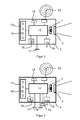
- FIG. 2 shows as an embodiment of the design of the device, if a 5kostante average heating power is to be achieved, with a constant but adjustable by the user waiting time.
- the electronics 12 connected to the optical detector 7 evaluate the output signal and forward the results to the optical display 13. This is advantageously realized by a series of LEDs 18 and the acoustic alarm transmitter 14 on the side or rear side of the device housing 4 , or via the antenna 15 for an alarm transmitter remotely connected by radio technology.
- a single button 16 is sufficient for switching on the device and operating the state modes. By pressing the button 16 for the first time, the device is switched on. After switching on, the device is in the mode I "waiting for flames", which is flame detection when heating or reheating.
- transition to mode III "wait” is usually almost always automatic in the absence of flames in the fire, but can also be done with the help of the button, just to be able to manually cycle the device sequentially through the various modes, in order to bring it into the appropriate fashion according to the status of the fire or also to be able to test the functions.
- the glowing heat of the glowing, not yet completely burned fuel is used before new fuel is added.
- This adjustable time is also the manipulated variable with which the power of the burner can be controlled.
- the device is again in Mode I: "Flame detection during heating or reheating".
- the maximum adjusting waiting time after detecting the absence of flames is adjustable with a knob 17 either in stages or continuously between 5 min to 5 h.
- the minimum waiting time of 5 minutes is also necessary here so that the device is not immediately in case of short-term failure of flames, as well as during the heating in the alarm mode. If flames start again after starting the waiting time, the waiting time starts again.
- the modes are optically displayed with a series of LEDs 18 in the example shown.
- the device is switched off by pressing the button 16 for more than 2 sec.
- a battery or battery 19 supplies power to the electronics. When supplying the battery, it is also possible to connect a charger.
- FIG. 3 shows the extension of the device by a temperature sensor 7a and an adjustability 17a of the target temperature of the heated space. This makes it possible to make the waiting break after extinguishing the flames dependent on the difference between the setpoint and the actual temperature.
- the setting option 17 is then used for the maximum waiting time, the to prevent the break being extended so far that it needs to be re-fueled.
- the knob is simply turned to the right stop and thus turned off by this time setting is extended so far that it no longer interferes with the process.
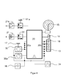
- FIG. 4 shows the block diagram as an embodiment of the electronics without p-processor.
- the sequence of the process steps with the partially conditional transitions controls a memory module 20 with a look-up table as state memory.
- the inputs 20a of the memory module are the addresses under which is stored as information of the respective next status of the controller and appears at the outputs 20b as a control signal and the optical display 13 with the LED 18 of the respective mode or the acoustic alarm transmitter 14 or via the transmitter the antenna 15 drives.
- a pulse generator 31 as a clock ensures that with the rising pulse edge, the address is transferred to the memory and with the falling information is output.
- the wait after the Failure of flames or the desired temperature of the room can be adjusted by means of two knobs 17 and 17 a on the housing from the outside.
- the optical sensor 7 is connected to the input of the bandpass filter 21.
- the comparator 22 ensures that only signals of a certain size reach the evaluation and the memory module is driven with a digital signal.
- the temperature sensor 7a is connected to the preamplifier 21a and compared via the comparator 22a with the setpoint temperature.
- Mode I is fulfilled with the device switched off. When heating up, you have to wait until there are significant flames, only then the device is switched on and then already in mode II "flame monitoring", after failure of flames it goes into mode III "wait” and after 5 min in mode IV "Alarm in the absence of flames" ( FIG. 4 ).
- the optical detector 7 realized here by a photoresistor, gives its output signal, ie a signal with the flicker frequency of the flames of about 4 to 20 Hz via the 4 to 20 Hz bandpass filter 21 to the gain-adjustable preamplifier 23 on whose output signal to the Stage detector 24 goes.
- the upper edge of the bandpass has been extended to 20 Hz, as the flicker frequency increases with a heavy chimney draft.
- the amplification of the preamplifier is now adjusted so that the green LED 24a still flashes at the minimum recognizable flame size in time with the flicker frequency.
- the electronics can also be realized for the comfortable execution of the device with the help of a micro-processor.
- the operation and display of the prior art with a digital display and two buttons for turning on the device and the operation of the menu as + - keys executable.
- Process step I is the same in the fueling and refueling function.
Landscapes
- Engineering & Computer Science (AREA)
- Chemical & Material Sciences (AREA)
- Combustion & Propulsion (AREA)
- Mechanical Engineering (AREA)
- General Engineering & Computer Science (AREA)
- Physics & Mathematics (AREA)
- Thermal Sciences (AREA)
- Feeding And Controlling Fuel (AREA)
- Direct Air Heating By Heater Or Combustion Gas (AREA)
- Control Of Combustion (AREA)
Applications Claiming Priority (1)
| Application Number | Priority Date | Filing Date | Title |
|---|---|---|---|
| DE102012105932.2A DE102012105932A1 (de) | 2012-07-03 | 2012-07-03 | Verfahren zum Betreiben einer Brennstelle und Brennstelle |
Publications (3)
| Publication Number | Publication Date |
|---|---|
| EP2682674A2 true EP2682674A2 (fr) | 2014-01-08 |
| EP2682674A3 EP2682674A3 (fr) | 2015-09-23 |
| EP2682674B1 EP2682674B1 (fr) | 2022-07-27 |
Family
ID=48747348
Family Applications (1)
| Application Number | Title | Priority Date | Filing Date |
|---|---|---|---|
| EP13173567.2A Withdrawn - After Issue EP2682674B1 (fr) | 2012-07-03 | 2013-06-25 | Détecteur de flammes |
Country Status (2)
| Country | Link |
|---|---|
| EP (1) | EP2682674B1 (fr) |
| DE (1) | DE102012105932A1 (fr) |
Cited By (3)
| Publication number | Priority date | Publication date | Assignee | Title |
|---|---|---|---|---|
| EP2979032B1 (fr) * | 2013-03-26 | 2017-01-04 | Gerd Reime | Dispositif et procédé de surveillance et de contrôle des flammes de processus de combustion |
| US20170184315A1 (en) * | 2015-12-23 | 2017-06-29 | Intel Corporation | Energy efficient combustion heater control |
| US10690057B2 (en) | 2017-04-25 | 2020-06-23 | General Electric Company | Turbomachine combustor end cover assembly with flame detector sight tube collinear with a tube of a bundled tube fuel nozzle |
Families Citing this family (1)
| Publication number | Priority date | Publication date | Assignee | Title |
|---|---|---|---|---|
| DE102023134832A1 (de) * | 2023-12-12 | 2025-06-12 | SiO2 Ventures GmbH | Verfahren und Vorrichtung zur Verbesserung des Wirkungsgrads und/oder der Reduzierung der Feinstaubbildung einer Verbrennung |
Citations (2)
| Publication number | Priority date | Publication date | Assignee | Title |
|---|---|---|---|---|
| DE102004028306B4 (de) | 2004-06-11 | 2006-02-16 | J. Eberspächer GmbH & Co. KG | Gebäudeofen, insbesondere Kachelofen, Grundofen oder dergleichen |
| EP2064491B1 (fr) | 2006-09-19 | 2010-02-17 | ABB Research LTD | Détecteur de flammes destiné à surveiller une flamme pendant un processus de combustion |
Family Cites Families (11)
| Publication number | Priority date | Publication date | Assignee | Title |
|---|---|---|---|---|
| US4436080A (en) * | 1982-03-17 | 1984-03-13 | Ting Enterprises, Inc. | Fireplace and stove apparatus |
| DE4409154A1 (de) * | 1993-03-22 | 1994-09-29 | Konrad Dr Mayr | Heizeinrichtung, insbesondere für feste Brennstoffe |
| US5913977A (en) * | 1998-03-25 | 1999-06-22 | Neuco, Inc. | Apparatus and method for internally coating live gas pipe joints or other discontinuities |
| US6047694A (en) * | 1998-05-22 | 2000-04-11 | Landstrom; Peter H. | Cooking enhancement system with fire retarding and steaming means |
| ATE247256T1 (de) * | 1998-05-29 | 2003-08-15 | Morso Jernstoberi As | Ofen für feste brennstoffe |
| US20070114296A1 (en) * | 2005-11-18 | 2007-05-24 | Pentwater Group, L.L.C. | Outdoor furnace monitor |
| US20070289589A1 (en) * | 2006-06-15 | 2007-12-20 | Mcfarland Daniel T | Intelligent and adaptive control system and method for wood burning stove |
| JP2010133677A (ja) * | 2008-12-08 | 2010-06-17 | Ueno Shoten:Kk | 薪ストーブ診断システム及び薪ストーブ診断プログラム |
| DE202008016788U1 (de) * | 2008-12-20 | 2010-03-04 | Ets Energie Transfersysteme Ag | Scheibenkollektor |
| FI122198B (fi) * | 2010-01-15 | 2011-10-14 | Tulikivi Oyj | Järjestely varaavassa tulisijassa |
| DE102013005151A1 (de) * | 2013-03-26 | 2014-10-02 | Gerd Reime | Vorrichtung und Verfahren zur Beobachtung und Überwachung von Flammen eines Verbrennungsprozesses |
-
2012
- 2012-07-03 DE DE102012105932.2A patent/DE102012105932A1/de not_active Withdrawn
-
2013
- 2013-06-25 EP EP13173567.2A patent/EP2682674B1/fr not_active Withdrawn - After Issue
Patent Citations (2)
| Publication number | Priority date | Publication date | Assignee | Title |
|---|---|---|---|---|
| DE102004028306B4 (de) | 2004-06-11 | 2006-02-16 | J. Eberspächer GmbH & Co. KG | Gebäudeofen, insbesondere Kachelofen, Grundofen oder dergleichen |
| EP2064491B1 (fr) | 2006-09-19 | 2010-02-17 | ABB Research LTD | Détecteur de flammes destiné à surveiller une flamme pendant un processus de combustion |
Cited By (4)
| Publication number | Priority date | Publication date | Assignee | Title |
|---|---|---|---|---|
| EP2979032B1 (fr) * | 2013-03-26 | 2017-01-04 | Gerd Reime | Dispositif et procédé de surveillance et de contrôle des flammes de processus de combustion |
| US20170184315A1 (en) * | 2015-12-23 | 2017-06-29 | Intel Corporation | Energy efficient combustion heater control |
| US10697651B2 (en) * | 2015-12-23 | 2020-06-30 | Intel Corporation | Energy efficient combustion heater control |
| US10690057B2 (en) | 2017-04-25 | 2020-06-23 | General Electric Company | Turbomachine combustor end cover assembly with flame detector sight tube collinear with a tube of a bundled tube fuel nozzle |
Also Published As
| Publication number | Publication date |
|---|---|
| EP2682674B1 (fr) | 2022-07-27 |
| DE102012105932A1 (de) | 2014-01-09 |
| EP2682674A3 (fr) | 2015-09-23 |
Similar Documents
| Publication | Publication Date | Title |
|---|---|---|
| EP2998654B1 (fr) | Procede de reconnaissance de casserole et plaque de cuisson | |
| DE69910381T2 (de) | Ofen für feste brennstoffe | |
| AT520713B1 (de) | Ofen | |
| DE69309896T2 (de) | Kochherd mit automatischer regelung | |
| DE102019107552A1 (de) | Grill mit kaltrauch-grillmodi | |
| DE69426578T2 (de) | Fernsteuerung für ein Haushaltsgerät | |
| DE19522300C2 (de) | Elektrische Sicherheitsvorrichtung für Kochstellen | |
| EP1212570B1 (fr) | Champ de Cuisson | |
| EP2682674B1 (fr) | Détecteur de flammes | |
| EP3489584A1 (fr) | Procédé de commande d'un appareil de cuisson doté d'un appareil de commande externe, appareil de cuisson et système | |
| DE202018106539U1 (de) | Automatischer Feuerschutzgasherd | |
| EP2500650B1 (fr) | Procédé de réglage d'un dispositif de chauffage | |
| DE102011001586A1 (de) | Sicherheitsvorrichtung für ein Elektrokochgerät mit einem Kochfeld | |
| DE4316182A1 (de) | Verfahren zum Steuern und/oder Regeln einer mit einem Feststoffkessel ausgerüsteten Heizungsanlage sowie Vorrichtung zur Durchführung des Verfahrens | |
| DE202018105594U1 (de) | Ein intelligenter Gasherd mit sicherer Zündung | |
| EP2979032B1 (fr) | Dispositif et procédé de surveillance et de contrôle des flammes de processus de combustion | |
| DE19907149A1 (de) | Dunstabzugsvorrichtung zum bestimmungsgemäßen Einsatz oberhalb einer Kochstelle | |
| DE102016103692A1 (de) | Überwachungssystem für eine Saunakabine, insbesondere zum Brandschutz und Saunakabine mit einem derartigen Überwachungssystem | |
| DE102008027880A1 (de) | Holzpellet-Saunaofen | |
| EP2949992A1 (fr) | Appareil de chauffage | |
| DE2827740A1 (de) | Gasfeuerstaette | |
| DE957065C (de) | Verfahren und Einrichtung zum UEberwachen der Flamme einer Feuerung | |
| EP2775210B1 (fr) | Système de chauffage avec un poêle à bois | |
| DE202008007810U1 (de) | Holzpellet-Saunaofen | |
| DE202023103400U1 (de) | Gasversorgungssteuersystem und Gasofen |
Legal Events
| Date | Code | Title | Description |
|---|---|---|---|
| PUAI | Public reference made under article 153(3) epc to a published international application that has entered the european phase |
Free format text: ORIGINAL CODE: 0009012 |
|
| AK | Designated contracting states |
Kind code of ref document: A2 Designated state(s): AL AT BE BG CH CY CZ DE DK EE ES FI FR GB GR HR HU IE IS IT LI LT LU LV MC MK MT NL NO PL PT RO RS SE SI SK SM TR |
|
| AX | Request for extension of the european patent |
Extension state: BA ME |
|
| PUAL | Search report despatched |
Free format text: ORIGINAL CODE: 0009013 |
|
| AK | Designated contracting states |
Kind code of ref document: A3 Designated state(s): AL AT BE BG CH CY CZ DE DK EE ES FI FR GB GR HR HU IE IS IT LI LT LU LV MC MK MT NL NO PL PT RO RS SE SI SK SM TR |
|
| AX | Request for extension of the european patent |
Extension state: BA ME |
|
| RIC1 | Information provided on ipc code assigned before grant |
Ipc: F23N 5/08 20060101ALI20150818BHEP Ipc: F23N 5/20 20060101ALI20150818BHEP Ipc: F23N 5/24 20060101ALI20150818BHEP Ipc: F23B 60/02 20060101AFI20150818BHEP Ipc: F24B 1/02 20060101ALI20150818BHEP Ipc: F23N 5/02 20060101ALI20150818BHEP |
|
| 17P | Request for examination filed |
Effective date: 20160323 |
|
| RBV | Designated contracting states (corrected) |
Designated state(s): AL AT BE BG CH CY CZ DE DK EE ES FI FR GB GR HR HU IE IS IT LI LT LU LV MC MK MT NL NO PL PT RO RS SE SI SK SM TR |
|
| 17Q | First examination report despatched |
Effective date: 20160902 |
|
| STAA | Information on the status of an ep patent application or granted ep patent |
Free format text: STATUS: EXAMINATION IS IN PROGRESS |
|
| GRAP | Despatch of communication of intention to grant a patent |
Free format text: ORIGINAL CODE: EPIDOSNIGR1 |
|
| STAA | Information on the status of an ep patent application or granted ep patent |
Free format text: STATUS: GRANT OF PATENT IS INTENDED |
|
| INTG | Intention to grant announced |
Effective date: 20220307 |
|
| GRAS | Grant fee paid |
Free format text: ORIGINAL CODE: EPIDOSNIGR3 |
|
| GRAA | (expected) grant |
Free format text: ORIGINAL CODE: 0009210 |
|
| STAA | Information on the status of an ep patent application or granted ep patent |
Free format text: STATUS: THE PATENT HAS BEEN GRANTED |
|
| AK | Designated contracting states |
Kind code of ref document: B1 Designated state(s): AL AT BE BG CH CY CZ DE DK EE ES FI FR GB GR HR HU IE IS IT LI LT LU LV MC MK MT NL NO PL PT RO RS SE SI SK SM TR |
|
| REG | Reference to a national code |
Ref country code: GB Ref legal event code: FG4D Free format text: NOT ENGLISH |
|
| PUAC | Information related to the publication of a b1 document modified or deleted |
Free format text: ORIGINAL CODE: 0009299EPPU |
|
| REG | Reference to a national code |
Ref country code: CH Ref legal event code: EP |
|
| STAA | Information on the status of an ep patent application or granted ep patent |
Free format text: STATUS: GRANT OF PATENT IS INTENDED |
|
| STAA | Information on the status of an ep patent application or granted ep patent |
Free format text: STATUS: THE APPLICATION HAS BEEN WITHDRAWN |
|
| REG | Reference to a national code |
Ref country code: AT Ref legal event code: REF Ref document number: 1507282 Country of ref document: AT Kind code of ref document: T Effective date: 20220815 Ref country code: CH Ref legal event code: PK Free format text: DIE ERTEILUNG WURDE VOM EPA WIDERRUFEN. |
|
| DB1 | Publication of patent cancelled |
Effective date: 20220729 |
|
| REG | Reference to a national code |
Ref country code: IE Ref legal event code: FG4D Free format text: LANGUAGE OF EP DOCUMENT: GERMAN |
|
| 18W | Application withdrawn |
Effective date: 20220721 |
|
| REG | Reference to a national code |
Ref country code: DE Ref legal event code: R107 Ref document number: 502013016194 Country of ref document: DE |
|
| REG | Reference to a national code |
Ref country code: AT Ref legal event code: REZ Ref document number: 1507282 Country of ref document: AT Kind code of ref document: T Effective date: 20220727 |