EP2682955A2 - Profilfüllerrohre in LAN-Kabeln - Google Patents
Profilfüllerrohre in LAN-Kabeln Download PDFInfo
- Publication number
- EP2682955A2 EP2682955A2 EP13305817.2A EP13305817A EP2682955A2 EP 2682955 A2 EP2682955 A2 EP 2682955A2 EP 13305817 A EP13305817 A EP 13305817A EP 2682955 A2 EP2682955 A2 EP 2682955A2
- Authority
- EP
- European Patent Office
- Prior art keywords
- cable
- bumpers
- bumper
- twisted pairs
- unshielded twisted
- Prior art date
- Legal status (The legal status is an assumption and is not a legal conclusion. Google has not performed a legal analysis and makes no representation as to the accuracy of the status listed.)
- Withdrawn
Links
- 239000000945 filler Substances 0.000 title description 9
- 229920000642 polymer Polymers 0.000 claims abstract description 20
- 230000009467 reduction Effects 0.000 claims abstract description 18
- 239000004020 conductor Substances 0.000 claims abstract description 12
- 230000002093 peripheral effect Effects 0.000 claims description 6
- 229910052729 chemical element Inorganic materials 0.000 claims 1
- 238000004891 communication Methods 0.000 description 19
- 238000010276 construction Methods 0.000 description 6
- 230000000694 effects Effects 0.000 description 6
- 239000013585 weight reducing agent Substances 0.000 description 6
- RYGMFSIKBFXOCR-UHFFFAOYSA-N Copper Chemical compound [Cu] RYGMFSIKBFXOCR-UHFFFAOYSA-N 0.000 description 5
- 239000000463 material Substances 0.000 description 5
- -1 Polyethylene Polymers 0.000 description 4
- 238000013461 design Methods 0.000 description 4
- 229920000915 polyvinyl chloride Polymers 0.000 description 4
- 239000004800 polyvinyl chloride Substances 0.000 description 4
- 239000004698 Polyethylene Substances 0.000 description 3
- 229910052802 copper Inorganic materials 0.000 description 3
- 239000010949 copper Substances 0.000 description 3
- 239000002184 metal Substances 0.000 description 3
- 229910052751 metal Inorganic materials 0.000 description 3
- 238000012986 modification Methods 0.000 description 3
- 230000004048 modification Effects 0.000 description 3
- 239000007787 solid Substances 0.000 description 3
- 238000001125 extrusion Methods 0.000 description 2
- 238000005187 foaming Methods 0.000 description 2
- 239000000446 fuel Substances 0.000 description 2
- ORQBXQOJMQIAOY-UHFFFAOYSA-N nobelium Chemical compound [No] ORQBXQOJMQIAOY-UHFFFAOYSA-N 0.000 description 2
- 230000000737 periodic effect Effects 0.000 description 2
- 229920000573 polyethylene Polymers 0.000 description 2
- 125000006850 spacer group Chemical group 0.000 description 2
- 238000005452 bending Methods 0.000 description 1
- 230000005540 biological transmission Effects 0.000 description 1
- 238000000576 coating method Methods 0.000 description 1
- 150000001875 compounds Chemical class 0.000 description 1
- 230000001627 detrimental effect Effects 0.000 description 1
- 230000005672 electromagnetic field Effects 0.000 description 1
- 230000007613 environmental effect Effects 0.000 description 1
- 229920000840 ethylene tetrafluoroethylene copolymer Polymers 0.000 description 1
- 239000000835 fiber Substances 0.000 description 1
- 238000007706 flame test Methods 0.000 description 1
- 239000012212 insulator Substances 0.000 description 1
- 230000014759 maintenance of location Effects 0.000 description 1
- 239000000203 mixture Substances 0.000 description 1
- 229920011301 perfluoro alkoxyl alkane Polymers 0.000 description 1
- 239000002861 polymer material Substances 0.000 description 1
- 239000004810 polytetrafluoroethylene Substances 0.000 description 1
- 229920001343 polytetrafluoroethylene Polymers 0.000 description 1
- 238000012545 processing Methods 0.000 description 1
- 239000000779 smoke Substances 0.000 description 1
- 238000006467 substitution reaction Methods 0.000 description 1
Images






Classifications
-
- H—ELECTRICITY
- H01—ELECTRIC ELEMENTS
- H01B—CABLES; CONDUCTORS; INSULATORS; SELECTION OF MATERIALS FOR THEIR CONDUCTIVE, INSULATING OR DIELECTRIC PROPERTIES
- H01B11/00—Communication cables or conductors
-
- H—ELECTRICITY
- H01—ELECTRIC ELEMENTS
- H01B—CABLES; CONDUCTORS; INSULATORS; SELECTION OF MATERIALS FOR THEIR CONDUCTIVE, INSULATING OR DIELECTRIC PROPERTIES
- H01B11/00—Communication cables or conductors
- H01B11/02—Cables with twisted pairs or quads
- H01B11/06—Cables with twisted pairs or quads with means for reducing effects of electromagnetic or electrostatic disturbances, e.g. screens
-
- H—ELECTRICITY
- H01—ELECTRIC ELEMENTS
- H01B—CABLES; CONDUCTORS; INSULATORS; SELECTION OF MATERIALS FOR THEIR CONDUCTIVE, INSULATING OR DIELECTRIC PROPERTIES
- H01B11/00—Communication cables or conductors
- H01B11/02—Cables with twisted pairs or quads
- H01B11/04—Cables with twisted pairs or quads with pairs or quads mutually positioned to reduce cross-talk
Definitions
- the present invention relates to the field of cables. More particularly, the present invention relates to filler components used in communication cables.
- Communication cables are broadly grouped into two arrangements, fiber optic cables and metal conductor cables, each of which has their own unique set of construction parameters that affect the quality of the communication signals carried therethrough.
- LAN Local Area Network
- LAN Local Area Network
- Other larger cables may em ploy more pairs of conductors.
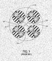
- One prior art manner for addressing such cross talk issues is to isolate the longest lay length pair in a four pair LAN cable, making it equidistant to the other three pairs in the same cable and as far as possible from other pairs in adjacent LAN cables.
- a plurality of unshielded twisted pairs are provided, each of which has a different lay length.
- the jacket encloses the plurality of unshielded twisted pairs, and the unshielded twisted pair that has the longest lay length among the plurality of unshielded twisted pairs positioned within the center of the jacket, substantially along the central longitudinal axis of the cable. See prior art Figure 2 .
- bumper elements are disposed around the central pair in between the outside pairs.
- the bumper elements are typically polymers formed as solid, foamed or hollow structures, however, alternative materials and structures may be used. These bumpers are advantageously of a dimension substantially equal to the diameter of a twisted pair, and are used for maintaining a regular geometry along the length of cable as shown in Figure 2 .
- the present arrangement overcomes certain drawbacks with the prior art by providing a low cost and effective bumper for maintaining proper spacing geometry of the twisted pairs within a communications/LAN cable without requiring the use of foamed polymers.
- Such improved bumpers are profiled so as to maintain a sufficient cross sectional diameter at any point along the length of the cable, while simultaneously significantly reducing polymer consumption making use of a profiled shape.
- the profiled shapes of the bumpers include significant airspace reducing the overall negative dielectric effects on the signals in the pairs adjacent the bumpers.
- the present arrangement is directed to a cable containing one or more polymeric elements for reduction of crosstalk.
- the cable includes a plurality of unshielded twisted pairs, each of which is an insulated conductor pair twisted around one another, each having a different lay length.
- a jacket encloses the plurality of unshielded twisted pairs, where an unshielded twisted pair, having the longest lay length among the plurality of unshielded twisted pairs is positioned within the center of the jacket such that an axis of the twisted pairs has the longest lay length substantially coincides with the central longitudinal axis of the cable.
- a plurality of bumper elements are disposed within the jacket in the interstices between said plurality of unshielded twisted pairs, where the bumper elements are profiled polymer structures.
- a cable containing one or more polymeric elements for reduction of crosstalk having a plurality of unshielded twisted pairs, each of which is an insulated conductor pair twisted around one another, the plurality of unshielded twisted pairs having different lay lengths.
- a central spacing element is provided around which the unshielded twisted pairs are arranged.
- One or more peripheral spacing elements are arranged within the unshielded twisted pairs to maintain the spacing of the unshielded twisted pairs.
- a jacket is provided enclosing the plurality of unshielded twisted pairs and central and peripheral spacing elements, where the spacing elements are profiled polymer structures.
- a cable 10 is provided having four twisted pairs 12a-12d of unshielded copper wire within an outer extruded jacket 14.
- cable 10 is shown to have four twisted pairs 12. However, the invention is not limited in this respect. The present invention may also be applied to cables having larger or smaller counts of twisted pairs 12 as desired. Twisted pairs 12a-12d are described as copper, but any desired conductive metal may be substituted as desired. Furthermore, the copper in pairs 12 are coated with typical polymer coatings, such as PE (Polyethylene) or FEP (Fluoronated Ethylene Polymer) or other insulators based on the desired cost and fire safety standards. Jacket 14 is also an extruded polymer as well, formed from PVC (Poly Vinyl Chloride) or FRPVC (Flame Resistant PVC), or other such polymer compositions.
- PE Polyethylene
- FEP Fluoronated Ethylene Polymer
- Jacket 14 is also an extruded polymer as well, formed from PVC (Poly Vinyl Chloride) or FRPVC (Flame Resistant PVC), or other such polymer compositions.
- each of twisted pairs 12a-12d has a different rate of rotational twisting resulting in different lay lengths.
- twisted pair 12a is presumed to have the shortest lay length and pair 12d has the longest lay length.
- a typical cable 10 may employ lay lengths in the ranges of 0.3" to 0.55" (0.3", 0.325", 0.35" and 0.55").
- lay lengths for pairs 12 are by way of illustration only, with the invention being equally applicable to any desired lay lengths depending on the desired crosstalk tolerance and desired mechanical (weight etc.) specifications.
- pairs 12a-12d are arranged in a three spoked wheel arrangement with pair 12d, having the longest lay length, being centrally located substantially along the center longitudinal axis of cable 10.
- the three pairs 12a-12c having the shorter lay lengths are disposed apart from one another, outwards towards the inside diameter of jacket 14.
- pairs 12a-12c are disposed substantially 120° apart.
- bumper elements 16 are disposed around central pair 12d and in between pairs 12a, 12b and 12c respectively.
- bumper elements 16 are typically polymers formed using specialized shapes to simultaneously maintain the geometry of pairs 12a-12d while reducing the amount of polymer used and maximizing the amount of open space/air to reduce any dielectric interference in the signals in pairs 12a-12d.
- contoured/shaped bumpers 16 A reduction of polymer content can be achieved by the introduction of contoured/shaped bumpers 16 as described in more detail below.
- the shapes for contoured bumpers 16 can differ, but, regardless of the shape, should retain its structural integrity against crushing, bending, pulling, and normal abuse of cable 10.
- the polymer materials used for bumpers 16 may be selected from, but are not limited to high temperature materials such as FEP, PTFE, PFA, ETFE, etc. and low tem perature materials such as PVC, FRPVC, PE, FRPE, PP, FRPP, LSZH compounds, etc...
- FIG. 4A a profiled shape for bumper 16 is shown in Figure 4A , where a profiled bumper 16 is provided, with a comparison to prior art bumpers such as that shown in Figure 4B .
- the normal bumper of prior art (4 pair LAN cable such as that in Figure 2 ) may have an ID (Inner Diameter) of 0.035" and an OD (Outer Diameter of 0.070").
- Figure 4A shows the present bumper 16 with eight (8) grooves 20, but otherwise having the same ID and OD.
- the exemplary bumper 16 is formed as a hollow structure having eight (8) grooves 20 disposed substantially equally around the outer circumference, with Figure 4A giving the dimensions of grooves 20.
- the exemplary groove 20 width is 0.004", where the wall depth is 0.0175" and the groove 20 depth is 0.0125.”
- the groove to wall ratio is 0.71 with a substantially 20% reduction in surface area.
- Table 1 shows the weight reduction that can be achieved with certain modifications to bumper 16 by adding 1-3 additional grooves 20 beyond the eight (8) grooves shown in Figure 4A .
- Figure 5 shows cable 10 using three bumpers 16 as defined in Figure 4A .
- a helical twist may be applied to bumpers 16 which may have either a constant or varied lay length along the length of bumper 16 and may be either helical (left or right handed) or SZ (periodic reversals).
- FIGS 6A and 6B illustrate one exemplary design having a two (2) fin shaped bumper 30.
- the two (2) fins are defined as "two" splines extending from a center point (although such a bumper 30 appears to be a single helically would strip.
- additional three (3) and four (4) spline designs for bumper 30 are within the contemplation of the present arrangement.
- the exemplary bumper 30 is formed as a 0.015" polymer strip (with each end extending from the center being defined as one of the "fins") having a width of 0.070" as with the prior described bumper 16.
- the helical twist rate is 0.250" (per full rotation), but it is understood that other forms and rates of twisting may be used.
- Figure 6B illustrates shows bumper 30 from Figure 6A in profile.
- Figure 7 shows cable 10 using three bumpers 30 as defined in Figure 6A .
- FIGS 8A and 8B illustrate a three (3) fin shaped bumper 32.
- the exemplary bumper 32 is formed as a 0.012" three finned polymer strip (with each of the three fins extending from the center) having an overall circumference of width of 0.070" as with the prior described bumper 16.
- the helical twist rate is 0.250" (per full rotation), but it is understood that other forms and rates of twisting may be used.
- Figure 8B shows the exemplary three (3) fin bumper 32 from Figure 8A in profile.
- Figure 9 show cable 10 using three bumpers 32 as defined in Figure 8A .
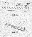
- FIGS 10A and 10B illustrate a four (4) fin shaped bumper 34.
- the exemplary bumper 34 is formed as a 0.010" four finned polymer strip (with each of the four fins extending from the center) having an overall circumference of width of 0.070" as with the prior described bumper 16.
- the helical twist rate is 0.250" (per full rotation), but it is understood that other forms and rates of twisting may be used.
- Figure 10B illustrates the exemplary four (4) fin bumper 34 from Figure 10A in profile.
- Figure 11 shows cable 10 using four bumpers 34 as defined in Figure 10A .
- Figures 12 and 13 illustrate another embodiment which, instead of a round bumper 16 with profiles/grooves 20, a shaped triangle bumper 36 may be used in cable 10 to create a sim ilar effect.
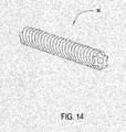
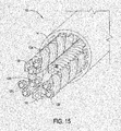
- Figures 14 and 15 illustrate another embodiment which, instead of a round bumper 16 with profiles/grooves 20, a star shaped bumper 38 may be used in cable 10 to create a sim ilar effect.
- each of the bumpers 30, 32, 34, 36 and 38 may employ a helical twist which may have either a constant or varied lay length along the length of the bumper(s) that can be either helical (left or right handed) or SZ (periodic reversals).
- the lay length of bumpers 30, 32, 34, 36 and 38 may employ a helical twist rate of substantially 1.00" but ranging from 0.010" to 10.00.”
- the finned and shaped bumpers 30, 32, 34, 36 and 38 ( Figures 6 , 8 , 10 , 12 and 14 respectively) also provide weight reduction advantages relative to the prior art arrangement of Figure 4B as shown in the following Table 2.
- the finned bumpers 30, 32 and 34 ( Figures 6 , 8 and 10 ) additionally provide surface area reduction relative to the prior art arrangement of Figure 4B as shown in the following Table 3. These reductions in surface area relative to the prior art bumpers provide an added advantage in that they reduce the dielectric interference with the signals in the adjacent pairs 12.
- each of cables 10 have the basic four (4) pairs 12 in typical LAN cables.
- the bumpers 16 or 30-38 in other twisted pair type LAN cables for similar geometric/shape retention.
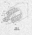
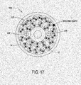
- Figure 16 shows an exemplary prior art twenty five (25) pair cable 100 which, among other components (pairs 12), includes a central spacing element 102 and peripheral spacers 104 that are used for maintaining the desired position of pairs 12 within the larger space enclosed by jacket 14 of cable 100.
- the same cable 100 may utilizes the bumpers 16 (and/or 30-38) as described above.
- spacing element 102 and peripheral spacers 104 rather than being solid fillers, employ profiled bumpers 102, 104 (or shaped helical twisted fillers - not shown), conferring the same advantages outlined above, including reduction in weight material and dielectric interferences.
- this larger twenty five (25) pair 12 LAN cable 100 is likewise a non-limiting example and that such profiled/shaped bumper elements 102 and 104 can equally be applied to small, midsized and even larger (25+) pair LAN cables as desired.
Landscapes
- Physics & Mathematics (AREA)
- Electromagnetism (AREA)
- Communication Cables (AREA)
Applications Claiming Priority (1)
| Application Number | Priority Date | Filing Date | Title |
|---|---|---|---|
| US13/539,978 US8895858B2 (en) | 2012-07-02 | 2012-07-02 | Profile filler tubes in LAN cables |
Publications (2)
| Publication Number | Publication Date |
|---|---|
| EP2682955A2 true EP2682955A2 (de) | 2014-01-08 |
| EP2682955A3 EP2682955A3 (de) | 2015-07-29 |
Family
ID=48703379
Family Applications (1)
| Application Number | Title | Priority Date | Filing Date |
|---|---|---|---|
| EP13305817.2A Withdrawn EP2682955A3 (de) | 2012-07-02 | 2013-06-18 | Profilfüllerrohre in LAN-Kabeln |
Country Status (6)
| Country | Link |
|---|---|
| US (1) | US8895858B2 (de) |
| EP (1) | EP2682955A3 (de) |
| KR (1) | KR20140004030A (de) |
| CN (1) | CN103531282A (de) |
| BR (1) | BR102013017039A2 (de) |
| CA (1) | CA2820311A1 (de) |
Families Citing this family (3)
| Publication number | Priority date | Publication date | Assignee | Title |
|---|---|---|---|---|
| WO2016094639A1 (en) | 2014-12-10 | 2016-06-16 | Wisconsin Alumni Research Foundation | Mini-intronic plasmid dna vaccines in combination with lag3 blockade |
| US10573431B2 (en) * | 2016-08-24 | 2020-02-25 | Ls Cable & System Ltd. | Communication cable |
| CN116825445B (zh) * | 2023-07-03 | 2024-07-16 | 广州市明兴电缆有限公司 | 一种用于电缆生产的绞合装置 |
Citations (1)
| Publication number | Priority date | Publication date | Assignee | Title |
|---|---|---|---|---|
| US7550674B2 (en) | 2007-02-22 | 2009-06-23 | Nexans | UTP cable |
Family Cites Families (16)
| Publication number | Priority date | Publication date | Assignee | Title |
|---|---|---|---|---|
| US7405360B2 (en) * | 1997-04-22 | 2008-07-29 | Belden Technologies, Inc. | Data cable with cross-twist cabled core profile |
| US7154043B2 (en) | 1997-04-22 | 2006-12-26 | Belden Technologies, Inc. | Data cable with cross-twist cabled core profile |
| US6365836B1 (en) | 1999-02-26 | 2002-04-02 | Nordx/Cdt, Inc. | Cross web for data grade cables |
| US20030121695A1 (en) | 2002-01-02 | 2003-07-03 | Wiebelhaus Dave A. | Local area network cabling arrangement utilizing corrugated tapes |
| US20030205402A1 (en) * | 2002-05-01 | 2003-11-06 | Fujikura Ltd. | Data transmission cable |
| US20050133246A1 (en) | 2003-12-22 | 2005-06-23 | Parke Daniel J. | Finned Jackets for lan cables |
| US7256351B2 (en) | 2005-01-28 | 2007-08-14 | Superior Essex Communications, Lp | Jacket construction having increased flame resistance |
| EP1851775A1 (de) | 2005-02-14 | 2007-11-07 | Panduit Corporation | Kabelsysteme und verfahren zur erweiterten kommunikation |
| US7375284B2 (en) * | 2006-06-21 | 2008-05-20 | Adc Telecommunications, Inc. | Multi-pair cable with varying lay length |
| US7560646B2 (en) * | 2007-05-31 | 2009-07-14 | Nexans | Profiled insulation and method for making the same |
| CA2724528C (en) | 2008-07-03 | 2017-03-28 | Adc Telecommunications, Inc. | Telecommunications wire having a channeled dielectric insulator and methods for manufacturing the same |
| US8319104B2 (en) | 2009-02-11 | 2012-11-27 | General Cable Technologies Corporation | Separator for communication cable with shaped ends |
| US8143522B2 (en) * | 2009-03-17 | 2012-03-27 | Nexans | LAN cable and method for making the same |
| US20100276178A1 (en) * | 2009-04-29 | 2010-11-04 | Joshua Keller | Profiled insulation and method for making the same |
| US8785782B2 (en) | 2010-01-08 | 2014-07-22 | Hyundai Mobis Co., Ltd | UTP cable of improved alien crosstalk characteristic |
| US9368258B2 (en) * | 2011-11-23 | 2016-06-14 | Nexans | Forward twisted profiled insulation for LAN cables |
-
2012
- 2012-07-02 US US13/539,978 patent/US8895858B2/en active Active
-
2013
- 2013-06-18 CA CA2820311A patent/CA2820311A1/en not_active Abandoned
- 2013-06-18 EP EP13305817.2A patent/EP2682955A3/de not_active Withdrawn
- 2013-07-02 CN CN201310332621.5A patent/CN103531282A/zh active Pending
- 2013-07-02 BR BRBR102013017039-9A patent/BR102013017039A2/pt not_active Application Discontinuation
- 2013-07-02 KR KR1020130077445A patent/KR20140004030A/ko not_active Withdrawn
Patent Citations (1)
| Publication number | Priority date | Publication date | Assignee | Title |
|---|---|---|---|---|
| US7550674B2 (en) | 2007-02-22 | 2009-06-23 | Nexans | UTP cable |
Also Published As
| Publication number | Publication date |
|---|---|
| US8895858B2 (en) | 2014-11-25 |
| CA2820311A1 (en) | 2014-01-02 |
| CN103531282A (zh) | 2014-01-22 |
| EP2682955A3 (de) | 2015-07-29 |
| BR102013017039A2 (pt) | 2015-06-30 |
| US20140000935A1 (en) | 2014-01-02 |
| KR20140004030A (ko) | 2014-01-10 |
Similar Documents
| Publication | Publication Date | Title |
|---|---|---|
| CA2677681C (en) | Data cable with cross-twist cabled core profile | |
| CA2545161C (en) | Data cable with cross-twist cabled core profile | |
| US7550674B2 (en) | UTP cable | |
| TWI240285B (en) | Communications cables with oppositely twinned and bunched insulated conductors | |
| US6297454B1 (en) | Cable separator spline | |
| US8344255B2 (en) | Cable with jacket including a spacer | |
| KR102708821B1 (ko) | 통신 케이블 | |
| US20150318075A1 (en) | Profiled cross filler in lan cables | |
| US20130126209A1 (en) | Forward twisted profiled insulation for lan cables | |
| EP2682955A2 (de) | Profilfüllerrohre in LAN-Kabeln | |
| US20140008102A1 (en) | Twisted pair spacer tape for use in lan cable | |
| WO2015080931A2 (en) | Reduced delay data cable | |
| CN103000265B (zh) | 一种微型安装线及其制造方法 | |
| JP2017010707A (ja) | 差動伝送用信号ケーブル | |
| KR20240176847A (ko) | 차량용 고차폐 이더넷 케이블 및 그의 제조 방법 |
Legal Events
| Date | Code | Title | Description |
|---|---|---|---|
| PUAI | Public reference made under article 153(3) epc to a published international application that has entered the european phase |
Free format text: ORIGINAL CODE: 0009012 |
|
| AK | Designated contracting states |
Kind code of ref document: A2 Designated state(s): AL AT BE BG CH CY CZ DE DK EE ES FI FR GB GR HR HU IE IS IT LI LT LU LV MC MK MT NL NO PL PT RO RS SE SI SK SM TR |
|
| AX | Request for extension of the european patent |
Extension state: BA ME |
|
| PUAL | Search report despatched |
Free format text: ORIGINAL CODE: 0009013 |
|
| AK | Designated contracting states |
Kind code of ref document: A3 Designated state(s): AL AT BE BG CH CY CZ DE DK EE ES FI FR GB GR HR HU IE IS IT LI LT LU LV MC MK MT NL NO PL PT RO RS SE SI SK SM TR |
|
| AX | Request for extension of the european patent |
Extension state: BA ME |
|
| RIC1 | Information provided on ipc code assigned before grant |
Ipc: H01B 11/06 20060101AFI20150624BHEP Ipc: H01B 11/04 20060101ALN20150624BHEP |
|
| 17P | Request for examination filed |
Effective date: 20160129 |
|
| RBV | Designated contracting states (corrected) |
Designated state(s): AL AT BE BG CH CY CZ DE DK EE ES FI FR GB GR HR HU IE IS IT LI LT LU LV MC MK MT NL NO PL PT RO RS SE SI SK SM TR |
|
| RAP1 | Party data changed (applicant data changed or rights of an application transferred) |
Owner name: NEXANS |
|
| 17Q | First examination report despatched |
Effective date: 20181108 |
|
| STAA | Information on the status of an ep patent application or granted ep patent |
Free format text: STATUS: THE APPLICATION IS DEEMED TO BE WITHDRAWN |
|
| 18D | Application deemed to be withdrawn |
Effective date: 20190521 |