EP2682967A1 - Condensateur électrolytique - Google Patents
Condensateur électrolytique Download PDFInfo
- Publication number
- EP2682967A1 EP2682967A1 EP12751790.2A EP12751790A EP2682967A1 EP 2682967 A1 EP2682967 A1 EP 2682967A1 EP 12751790 A EP12751790 A EP 12751790A EP 2682967 A1 EP2682967 A1 EP 2682967A1
- Authority
- EP
- European Patent Office
- Prior art keywords
- resin
- connection part
- electrolytic capacitor
- mica
- lead terminal
- Prior art date
- Legal status (The legal status is an assumption and is not a legal conclusion. Google has not performed a legal analysis and makes no representation as to the accuracy of the status listed.)
- Granted
Links
Images
Classifications
-
- H—ELECTRICITY
- H01—ELECTRIC ELEMENTS
- H01G—CAPACITORS; CAPACITORS, RECTIFIERS, DETECTORS, SWITCHING DEVICES, LIGHT-SENSITIVE OR TEMPERATURE-SENSITIVE DEVICES OF THE ELECTROLYTIC TYPE
- H01G9/00—Electrolytic capacitors, rectifiers, detectors, switching devices, light-sensitive or temperature-sensitive devices; Processes of their manufacture
- H01G9/004—Details
- H01G9/08—Housing; Encapsulation
- H01G9/10—Sealing, e.g. of lead-in wires
-
- H—ELECTRICITY
- H01—ELECTRIC ELEMENTS
- H01G—CAPACITORS; CAPACITORS, RECTIFIERS, DETECTORS, SWITCHING DEVICES, LIGHT-SENSITIVE OR TEMPERATURE-SENSITIVE DEVICES OF THE ELECTROLYTIC TYPE
- H01G9/00—Electrolytic capacitors, rectifiers, detectors, switching devices, light-sensitive or temperature-sensitive devices; Processes of their manufacture
- H01G9/004—Details
- H01G9/04—Electrodes or formation of dielectric layers thereon
- H01G9/06—Mounting in containers
Definitions
- the present invention relates to an electrolytic capacitor having a lead wire which is formed by plating a metal composed of mainly tin on an aluminum wire.
- An electrolytic capacitor comprises a capacitor element, a electrolytic solution for driving the capacitor or a solid electrolyte, and an outer casing.
- This capacitor element is formed by winding an anode foil containing a valve action metal such as tantalum and aluminum together with a cathode foil.
- the electrolytic solution for driving the capacitor or the solid electrolyte is retained in the capacitor element.
- the outer casing houses the capacitor element and the driving electrolytic solution or the solid electrolyte.
- the anode foil of such an electrolytic capacitor is connected to an anode electrode via a lead terminal.
- the cathode foil is connected to a cathode electrode via a lead terminal.
- the lead terminal has three parts, which are, an aluminum wire which connects to the anode or cathode foil, a connection part formed at the end of the aluminum wire, and a lead wire which is joined to the connection part.
- a lead plating layer is formed on the lead wire.
- the end of this lead wire is joined to the connection part formed at the end of the aluminum wire by means of arc welding.
- lead used in the lead wire is a substance that is not only harmful to the human body but has a bad influence on the natural environment. Accordingly, in recent years, development of electronic parts that do not use any lead has been promoted in regards to environmental protection.
- a capacitor that does not use any lead uses a copper-coated steel wire applied with tin plating consisting of 100% tin as the lead wire.
- This tin plating is joined by inserting and arc welding the copper-coated steel wire into a recessed portion provided at one end of the round bar portion of the lead wire.
- a fusion layer of copper, tin, and aluminum produced by heating copper, tin plating, and aluminum is formed at the connecting part between the lead wire and the round bar portion.
- whiskers may develop from the fusion layer produced at the connection part between the round bar portion of the lead terminal and the tin-plated lead wire. These whiskers are fibrous crystals of tin, and may reach a length of 1 mm or more against a diameter of 1 ⁇ m. Due to the development of these whiskers, in the worst case scenario there is a risk of short circuiting between a pair of lead terminals. There is also a risk of the whisker falling onto a substrate and causing a short circuit between other electronic parts and between substrate patterns.
- Patent Document 2 the lead wire of the capacitor is washed with an alkaline washing fluid. After removing this washing fluid, it is applied to heat treatment to prevent the development of whiskers.
- Patent Document 3 the welding point of connecting the CP wire to the aluminum round bar by welding is provided with a waterproof film, and whisker growth is suppressed by this waterproof film.
- Patent Document 4 vacuum state is made and filled with an inert gas, and high temperature heat treatment is applied. By doing so, internal applied force of the welding point of the capacitor lead wire is relaxed, and whisker development at the welding portion is prevented.
- Patent Documents 2 and 4 the development of whiskers could not be completely prevented, and therefore effects were insufficient.
- Patent Document 3 there was a possibility that the growing whisker breaks through the resin and the whisker will appear outside the resin, and therefore the effect was insufficient.
- the present invention was provided to solve the problems described above.
- the object of the present invention is to provide an aluminum electrolytic capacitor employing a lead terminal that does not use lead, wherein the development and growth of a whisker in the lead terminal is suppressed.
- the present inventors in order to solve the above problems, have selected a material for coating the lead terminal, thereby resulting in completion of the present invention.
- the electrolytic capacitor of the present invention is an electrolytic capacitor comprising a lead terminal including an aluminum wire that connects to an anode or cathode foil, a connection part formed at the end of the aluminum wire, and a lead wire connected to the connection part.
- a liquid curing resin containing a flaky filler is applied to or filled in the surface of the connection part of said lead terminal to form a cured resin layer.
- the capacitor of the present invention may also comprise the following embodiments.
- the present invention as above, it becomes possible to suppress whisker development by applying or filling a resin to or in the connection part of the lead wire. Further, even if a whisker develops and grows within the resin, the whisker can be suppressed by the flaky filler in the liquid curing resin from growing towards the resin surface and appearing therefrom.
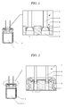
- Figure 1 shows the cross-sectional view of the electrolytic capacitor in the present embodiment.
- Symbol 1 in Figure 1 shows a capacitor element of an anode foil and a cathode foil that are wound together with a separator therebetween.
- Capacitor element 1 is configured to be housed in an outer casing 2 together with a driving electrolyte or a solid electrolyte.
- the anode and cathode foils of the capacitor element 1 are provided with electrodes (not shown) .
- the electrodes of these anode and cathode foils are connected with lead terminals 3 for connecting with the outside.
- the lead terminal 3 is configured from three parts, that are an aluminum wire 4, a connection part 5, and a lead wire 6.
- This aluminum wire 4 is connected to the anode or cathode foil.
- the connection part 5 is integrally formed at the end of this aluminum wire 4.
- the lead wire 6 plated with a metal composed of mainly tin formed thereon is connected to the connection part 5.
- Various methods can be utilized as the method to connect the connection part 5 and the lead wire 6. For example, they may be connected by inserting and arc welding the lead wire 6 into a recessed portion formed in the connection part 5.
- connection part 5 The surface of the connection part 5 is coated by a resin layer 7.
- This resin layer 7 is provided by applying and curing a liquid curing resin containing 1 wt% or more of a flaky filler. As shown in Figure 1 , the lead terminal 3 having the coated connection part 5 is inserted into a through-hole 8 of seal 9. A liquid curing resin is filled and cured in the gap between the lead wire 6 and the through-hole 8 to form the resin layer 7.
- This resin layer 7 is the liquid curing resin filled in the gap between the through-hole 8 and the lead wire 6. Accordingly, as shown in Figure 2 , the liquid curing resin may be filled not only in the through-hole 8 into which the lead wire 6 is inserted, but also overflowing on all surface of a seal 9 on the lead-out side of the lead wire 6. Further, the seal 9 may be provided with a belt-like recessed portion so that the through-holes 8 are linked to each other, and the liquid curing resin poured therein. In other words, a portion or all of the surface of the seal 9 comprising through-holes 8 may be filled.
- the liquid curing resin of the present invention is not particularly limited, examples of which include a silicone resin, a modified silicone resin, a hybrid silicone resin, an epoxy resin, a phenol resin, a melamine resin, a urea resin, a fluorine resin, a urethane resin, a urethane acrylic resin, an acrylic resin, a polyester resin, and a polyimide resin.
- silicone resins an addition curing silicone, a condensation curing silicone, an addition curing modified silicone, or a condensation curing modified silicone, as well as a hybrid silicone resin are preferred in regards to heat resistance and weather resistance.
- the liquid curing resin may contain any other components according to the necessity in a range that does not compromise the object of the present invention.
- the any component includes e.g. the following (1) to (6).
- the liquid curing resin may be treated so that the range of area that the liquid curing resin was applied or filled can be distinguished. It can, for example, be treated to contain a dyestuff in order to improve visibility. Alternatively, an element different from the element that configures the lead terminal can be mixed therein. The liquid curing resin can be applied or filled by confirmation of this element. By doing so, verification of whether the liquid curing resin is appropriately applied or filled will be facilitated in the manufacturing step.
- the flaky filler of the present invention is a material for suppressing whisker growth.
- a flaky filler include but are not particularly limited to a natural mica such as bronze mica, white mica, and sericite, a synthetic mica such as fluorine bronze mica, potassium tetrasilicone mica, sodium tetrasilicone mica, sodium taeniolite, and lithium taeniolite, a natural smectite such as montmorillonite, a synthetic smectite such as sodium hectorite, lithium hectorite, and saponite, bentonite, talc, expanded graphite, aluminum silicate, magnesium silicate, boehmite, clay, diatomite, carbon black, silica, barium sulfate, calcium carbonate, magnesium carbonate, metal oxide, graphite, and aluminum hydroxide.
- a natural mica such as bronze mica, white mica, and sericite
- a synthetic mica such as fluorine bronze
- natural micas such as inexpensive white mica and synthetic micas are preferred because of their ease in aspect ratio adjustment.
- These flaky fillers have a large planar portion relative to the weight added. Accordingly, just a small amount of the flaky filler added to the resin will increase the probability of planar portion collision during whisker growth, and whisker growth can be suppressed. In contrast, with a filler that does not have a large planar portion or with a spherical or a needle-like filler, whisker growth cannot be effectively suppressed because the filler is thrown aside even when whiskers collide, or the whiskers avoid the filler when growing.
- the average aspect ratio of 70 or higher As a shape of the flaky filler, it is desirable to have the average aspect ratio of 70 or higher. When the average aspect ratio is 70 or higher, whisker growth suppression effect is high and appearance of a whisker from the resin surface can be effectively prevented.
- the average particle size is not particularly limited but is preferably 1000 ⁇ m or less, more preferably 200 ⁇ m or less. When the average particle size of the flaky filler is greater than 1000 ⁇ m, applicability and mouldability of the liquid curing resin is significantly reduced.
- the flaky filler is added in the range of 1 wt% or more and 50 wt% and less of the liquid curing resin. Effect cannot be sufficiently exerted when the amount of the filler added is less than 1 wt%, and application of the resin becomes difficult or mouldability becomes significantly reduced if it is greater than 50 wt%.
- These flaky fillers may be applied to the hydrophobic treatment with a surface treatment agent such as a silane coupling agent, a quaternary ammonium salt, and a polyether.
- a surface treatment agent such as a silane coupling agent, a quaternary ammonium salt, and a polyether.
- any form can be used for the flaky filler such as a powder, a dispersed solution type, and granules, as long as it is possible to be dispersed into the liquid curing resin. Because any form can be used as the flaky filler, various types of flaky fillers can be added.
- the liquid curing resin of the resin layer 7 of the present embodiment having the above configuration has a flaky filler added thereto. Accordingly, even when a whisker develops in the connection part 5 and grows towards the resin layer 7 side, the tip will contact the flaky filler inside the resin layer 7 and thus any further whisker growth can be prevented.
- Example 1 of the present invention uses an addition curing silicone as the liquid curing resin.
- This addition curing silicone is prepared by uniformly mixing components (1) to (5) below.
- connection part 5 of the lead terminal 3 was formed the resin layer 7. Then, this lead terminal 3 was employed to fabricate ten electrolytic capacitors.
- Example 2 of the present invention similarly to Example 1, uses an addition curing silicone as the liquid curing resin.
- the addition curing silicone of Example 2 is prepared by uniformly mixing components (1) to (4) of Example 1 and component 5 below.
- connection part 5 of the lead terminal 3 was formed the resin layer 7. Then, this lead terminal 3 was employed to fabricate ten electrolytic capacitors.
- Example 3 of the present invention uses an addition curing polyisobutylene-silicone hybrid composition as the liquid curing resin.
- This addition curing polyisobutylene-silicone hybrid composition is prepared by uniformly mixing components (1) to (5) below.
- connection part 5 of the lead terminal 3 was formed the resin layer 7. Then, this lead terminal 3 was employed to fabricate ten electrolytic capacitors.
- Example 4 of the present invention similarly to Example 3, uses an addition curing polyisobutylene-silicone hybrid composition as the liquid curing resin.
- the addition curing polyisobutylene-silicone hybrid composition of Example 4 is prepared by uniformly mixing components (1) to (3) of Example 3 and component 4 below.
- connection part 5 of the lead terminal 3 was formed the resin layer 7. Then, this lead terminal 3 was employed to fabricate ten electrolytic capacitors.
- Comparative Example 1 uses an addition curing silicone as the liquid curing resin.
- This addition curing silicone was fabricated similarly to Examples 1 and 2 except that component 5 of Examples 1 and 2 was not added. In other words, components (1) to (4) of Examples 1 and 2 were uniformly mixed to prepare the addition curing silicone.
- This addition curing silicone was applied to the connection part 5 of the lead terminal 3 to form the resin layer 7. Then, this lead terminal 3 was employed to fabricate ten electrolytic capacitors.
- Comparative Example 2 uses an addition curing polyisobutylene-silicone hybrid composition as the liquid curing resin.
- This addition curing polyisobutylene-silicone hybrid composition was fabricated similarly to Examples 3 and 4 except that (4) of Examples 3 and 4 was not added. In other words, components (1) to (3) of Examples 3 and 4 were uniformly mixed to prepare the addition curing polyisobutylene-silicone hybrid composition.
- This addition curing polyisobutylene-silicone hybrid composition was applied to the connection part 5 of the lead terminal 3 to form the resin layer 7. Then, this lead terminal 3 was employed to fabricate ten electrolytic capacitors.
- Comparative Example 3 ten electrolytic capacitors were fabricated without applying the liquid curing resin to the lead terminal 3. In other words, it is a Comparative Example where the resin layer 7 composed of coating the liquid curing resin was not formed.
- Table 1 represents the number of capacitors out of 10 where a whisker appeared on the resin surface after 4000 and 5000 hours for each of the capacitors from Examples 1-4 and Comparative Examples 1 and 2 configured by the above methods.
- Comparative Example 3 the number of capacitors with whisker development at the connection part is shown.
- Table 1 also shows the surface state after 5000 hours.
- " ⁇ ” in the Table is a state where no whisker is seen near the resin surface.
- "x” in the Table is a state where no whisker appeared outside the resin, but a whisker is present near the resin surface, or a state where a whisker is present at the connection part.
- Example 1 100 0/10 0/10 ⁇
- Example 3 100 0/10 0/10 ⁇
- Examples 1-4 In the lead terminals of Examples 1-4 where a resin supplemented with a flaky filler is applied, it is seen that no whisker appears from the resin surface not only after 4000 hours but still after 5000 hours. Further, as shown with " ⁇ " and "x" in the Table, Examples 1-4 are a state where no whisker is seen near the resin surface.
Landscapes
- Engineering & Computer Science (AREA)
- Power Engineering (AREA)
- Microelectronics & Electronic Packaging (AREA)
- Compositions Of Macromolecular Compounds (AREA)
- Paints Or Removers (AREA)
Applications Claiming Priority (2)
| Application Number | Priority Date | Filing Date | Title |
|---|---|---|---|
| JP2011044440A JP2012182326A (ja) | 2011-03-01 | 2011-03-01 | 電解コンデンサ |
| PCT/JP2012/052790 WO2012117820A1 (fr) | 2011-03-01 | 2012-02-07 | Condensateur électrolytique |
Publications (3)
| Publication Number | Publication Date |
|---|---|
| EP2682967A1 true EP2682967A1 (fr) | 2014-01-08 |
| EP2682967A4 EP2682967A4 (fr) | 2014-10-22 |
| EP2682967B1 EP2682967B1 (fr) | 2019-11-06 |
Family
ID=46757759
Family Applications (1)
| Application Number | Title | Priority Date | Filing Date |
|---|---|---|---|
| EP12751790.2A Active EP2682967B1 (fr) | 2011-03-01 | 2012-02-07 | Condensateur électrolytique |
Country Status (4)
| Country | Link |
|---|---|
| EP (1) | EP2682967B1 (fr) |
| JP (1) | JP2012182326A (fr) |
| CN (1) | CN103403824B (fr) |
| WO (1) | WO2012117820A1 (fr) |
Cited By (2)
| Publication number | Priority date | Publication date | Assignee | Title |
|---|---|---|---|---|
| EP3282462A4 (fr) * | 2015-04-09 | 2019-01-09 | Nesscap Co., Ltd. | Dispositif à double couche électrique |
| US11482383B2 (en) | 2017-08-31 | 2022-10-25 | Panasonic Intellectual Property Management Co., Ltd. | Electrolytic capacitor |
Families Citing this family (5)
| Publication number | Priority date | Publication date | Assignee | Title |
|---|---|---|---|---|
| JP5929665B2 (ja) * | 2012-09-24 | 2016-06-08 | 富士通株式会社 | 電解コンデンサとその製造方法 |
| JP6079322B2 (ja) * | 2013-03-08 | 2017-02-15 | 横浜ゴム株式会社 | 熱硬化性樹脂組成物 |
| JP6920593B2 (ja) * | 2016-05-31 | 2021-08-18 | パナソニックIpマネジメント株式会社 | 電解コンデンサおよびその製造方法 |
| KR102557268B1 (ko) * | 2022-04-18 | 2023-07-20 | 동진기업(주) | 전해액 누출 방지 가능한 커패시터 |
| WO2024225437A1 (fr) * | 2023-04-28 | 2024-10-31 | 日本ケミコン株式会社 | Condensateur électrolytique en aluminium pour refroidissement par immersion dans un liquide, procédé de refroidissement de condensateur électrolytique en aluminium et procédé de refroidissement d'appareil électronique |
Family Cites Families (21)
| Publication number | Priority date | Publication date | Assignee | Title |
|---|---|---|---|---|
| JPH01270214A (ja) * | 1988-04-20 | 1989-10-27 | Sanyo Electric Co Ltd | 固体電解コンデンサの製造方法 |
| JP3123242B2 (ja) * | 1992-07-30 | 2001-01-09 | 松下電器産業株式会社 | 電子部品 |
| JPH07201679A (ja) * | 1993-12-28 | 1995-08-04 | Matsushita Electric Ind Co Ltd | アルミ電解コンデンサ |
| JP2000124073A (ja) | 1998-10-14 | 2000-04-28 | Matsushita Electric Ind Co Ltd | アルミ電解コンデンサ |
| JP3957142B2 (ja) * | 2001-05-11 | 2007-08-15 | 克巳 小林 | 面実装型アルミニウム電解コンデンサ用封口ゴムの製造方法 |
| JP2005142416A (ja) * | 2003-11-07 | 2005-06-02 | Nisshinbo Ind Inc | 密閉型蓄電装置及びその製造方法 |
| WO2005064628A1 (fr) * | 2003-12-25 | 2005-07-14 | Kohoku Kogyo Co., Ltd. | Cosse a languette pour condensateur electrolytique |
| JP2007067146A (ja) | 2005-08-31 | 2007-03-15 | Niyuucentral Kk | コンデンサ用リード線の製造方法 |
| JP4732181B2 (ja) * | 2006-02-15 | 2011-07-27 | 湖北工業株式会社 | タブ端子の製造方法およびその方法により得られるタブ端子 |
| JP2007335714A (ja) | 2006-06-16 | 2007-12-27 | Matsushita Electric Ind Co Ltd | コンデンサ |
| WO2008038808A1 (fr) * | 2006-09-28 | 2008-04-03 | Nippon Chemi-Con Corporation | Produit d'étanchéité pour des condensateurs électrolytiques et condensateur électrolytique utilisant ce produit d'étanchéité |
| JP2008130782A (ja) | 2006-11-21 | 2008-06-05 | Niyuucentral Kk | コンデンサ用リード線の製造方法 |
| JP4947296B2 (ja) * | 2007-03-30 | 2012-06-06 | 日本ケミコン株式会社 | 電解コンデンサ用封口体及び該封口体を用いた電解コンデンサ |
| WO2008143005A1 (fr) * | 2007-05-10 | 2008-11-27 | Hitachi Maxell, Ltd. | Elément électrochimique et son procédé de fabrication |
| JP2010003731A (ja) * | 2008-06-18 | 2010-01-07 | Sanyo Electric Co Ltd | 電解コンデンサ |
| JP5360071B2 (ja) * | 2008-12-18 | 2013-12-04 | 日本ケミコン株式会社 | コンデンサ用リード端子及びその製造方法 |
| JP2010239058A (ja) * | 2009-03-31 | 2010-10-21 | Nippon Chemicon Corp | 電解コンデンサの製造方法 |
| JP2010258220A (ja) * | 2009-04-24 | 2010-11-11 | Nippon Chemicon Corp | 電解コンデンサの製造方法及び電解コンデンサ |
| JP5515391B2 (ja) * | 2009-04-24 | 2014-06-11 | 日本ケミコン株式会社 | 電解コンデンサの製造方法及び電解コンデンサ |
| JP2010258219A (ja) * | 2009-04-24 | 2010-11-11 | Nippon Chemicon Corp | 電解コンデンサの製造方法及び電解コンデンサ |
| CN201663055U (zh) * | 2010-01-27 | 2010-12-01 | 南通汇丰电子科技有限公司 | 高强度易焊环保型电容器引线 |
-
2011
- 2011-03-01 JP JP2011044440A patent/JP2012182326A/ja not_active Withdrawn
-
2012
- 2012-02-07 EP EP12751790.2A patent/EP2682967B1/fr active Active
- 2012-02-07 CN CN201280010131.7A patent/CN103403824B/zh active Active
- 2012-02-07 WO PCT/JP2012/052790 patent/WO2012117820A1/fr not_active Ceased
Cited By (4)
| Publication number | Priority date | Publication date | Assignee | Title |
|---|---|---|---|---|
| EP3282462A4 (fr) * | 2015-04-09 | 2019-01-09 | Nesscap Co., Ltd. | Dispositif à double couche électrique |
| US10658128B2 (en) | 2015-04-09 | 2020-05-19 | Nesscap Co., Ltd. | Electric double-layer device |
| US11482383B2 (en) | 2017-08-31 | 2022-10-25 | Panasonic Intellectual Property Management Co., Ltd. | Electrolytic capacitor |
| US11776762B2 (en) | 2017-08-31 | 2023-10-03 | Panasonic Intellectual Property Management Co., Ltd. | Electrolytic capacitor |
Also Published As
| Publication number | Publication date |
|---|---|
| JP2012182326A (ja) | 2012-09-20 |
| CN103403824A (zh) | 2013-11-20 |
| WO2012117820A1 (fr) | 2012-09-07 |
| EP2682967A4 (fr) | 2014-10-22 |
| CN103403824B (zh) | 2017-09-29 |
| EP2682967B1 (fr) | 2019-11-06 |
Similar Documents
| Publication | Publication Date | Title |
|---|---|---|
| EP2682967B1 (fr) | Condensateur électrolytique | |
| EP3593367B1 (fr) | Ensemble condensateur à électrolyte solide | |
| US10014116B2 (en) | Conductive polymer composition with a dual crosslinker system for capacitors | |
| EP3542381B1 (fr) | Configuration de fil de connexion destinée à un condensateur électrolytique solide | |
| US10643797B2 (en) | Casing material for a solid electrolytic capacitor | |
| JP2015073097A (ja) | 高温多湿条件下での使用のための固体電解コンデンサ | |
| JP5704049B2 (ja) | 導電性回路形成方法 | |
| US20250357054A1 (en) | Low Inductance Electroytic Capacitor | |
| KR101125743B1 (ko) | 높은 열전도 효율을 가지는 방열 패드 및 이의 제조방법 | |
| CN1883021A (zh) | 固体电解电容器 | |
| US9754730B2 (en) | Low profile multi-anode assembly in cylindrical housing | |
| JP2026510545A (ja) | 低インダクタンス電解質コンデンサ | |
| JP2004153044A (ja) | 導電性ペースト及び固体電解コンデンサ | |
| JPWO2015194129A1 (ja) | 固体電解コンデンサおよびその製造方法 | |
| JP2001023869A (ja) | 固体電解コンデンサ用導電性ペースト | |
| HK40126006A (zh) | 低电感电解电容器 | |
| JPH1173828A (ja) | ポリマー碍子 | |
| HK40097517A (zh) | 低电感电解电容器 | |
| HK40005202A (en) | Lead wire configuration for a solid electrolytic capacitor | |
| HK40005064A (en) | Casing material for a solid electrolytic capacitor | |
| HK40005064B (zh) | 用於固体电解质电容器的壳体材料 |
Legal Events
| Date | Code | Title | Description |
|---|---|---|---|
| PUAI | Public reference made under article 153(3) epc to a published international application that has entered the european phase |
Free format text: ORIGINAL CODE: 0009012 |
|
| 17P | Request for examination filed |
Effective date: 20131001 |
|
| AK | Designated contracting states |
Kind code of ref document: A1 Designated state(s): AL AT BE BG CH CY CZ DE DK EE ES FI FR GB GR HR HU IE IS IT LI LT LU LV MC MK MT NL NO PL PT RO RS SE SI SK SM TR |
|
| DAX | Request for extension of the european patent (deleted) | ||
| A4 | Supplementary search report drawn up and despatched |
Effective date: 20140919 |
|
| RIC1 | Information provided on ipc code assigned before grant |
Ipc: H01G 9/10 20060101AFI20140915BHEP |
|
| 17Q | First examination report despatched |
Effective date: 20160816 |
|
| STAA | Information on the status of an ep patent application or granted ep patent |
Free format text: STATUS: EXAMINATION IS IN PROGRESS |
|
| GRAP | Despatch of communication of intention to grant a patent |
Free format text: ORIGINAL CODE: EPIDOSNIGR1 |
|
| STAA | Information on the status of an ep patent application or granted ep patent |
Free format text: STATUS: GRANT OF PATENT IS INTENDED |
|
| INTG | Intention to grant announced |
Effective date: 20190619 |
|
| RIN1 | Information on inventor provided before grant (corrected) |
Inventor name: ASHINO, HIROTUGU Inventor name: SAIKI, TAKEAKI |
|
| GRAS | Grant fee paid |
Free format text: ORIGINAL CODE: EPIDOSNIGR3 |
|
| GRAA | (expected) grant |
Free format text: ORIGINAL CODE: 0009210 |
|
| STAA | Information on the status of an ep patent application or granted ep patent |
Free format text: STATUS: THE PATENT HAS BEEN GRANTED |
|
| AK | Designated contracting states |
Kind code of ref document: B1 Designated state(s): AL AT BE BG CH CY CZ DE DK EE ES FI FR GB GR HR HU IE IS IT LI LT LU LV MC MK MT NL NO PL PT RO RS SE SI SK SM TR |
|
| REG | Reference to a national code |
Ref country code: GB Ref legal event code: FG4D |
|
| REG | Reference to a national code |
Ref country code: CH Ref legal event code: EP Ref country code: AT Ref legal event code: REF Ref document number: 1199933 Country of ref document: AT Kind code of ref document: T Effective date: 20191115 |
|
| REG | Reference to a national code |
Ref country code: IE Ref legal event code: FG4D |
|
| REG | Reference to a national code |
Ref country code: DE Ref legal event code: R096 Ref document number: 602012065441 Country of ref document: DE |
|
| REG | Reference to a national code |
Ref country code: NL Ref legal event code: MP Effective date: 20191106 |
|
| REG | Reference to a national code |
Ref country code: LT Ref legal event code: MG4D |
|
| PG25 | Lapsed in a contracting state [announced via postgrant information from national office to epo] |
Ref country code: PT Free format text: LAPSE BECAUSE OF FAILURE TO SUBMIT A TRANSLATION OF THE DESCRIPTION OR TO PAY THE FEE WITHIN THE PRESCRIBED TIME-LIMIT Effective date: 20200306 Ref country code: ES Free format text: LAPSE BECAUSE OF FAILURE TO SUBMIT A TRANSLATION OF THE DESCRIPTION OR TO PAY THE FEE WITHIN THE PRESCRIBED TIME-LIMIT Effective date: 20191106 Ref country code: PL Free format text: LAPSE BECAUSE OF FAILURE TO SUBMIT A TRANSLATION OF THE DESCRIPTION OR TO PAY THE FEE WITHIN THE PRESCRIBED TIME-LIMIT Effective date: 20191106 Ref country code: LT Free format text: LAPSE BECAUSE OF FAILURE TO SUBMIT A TRANSLATION OF THE DESCRIPTION OR TO PAY THE FEE WITHIN THE PRESCRIBED TIME-LIMIT Effective date: 20191106 Ref country code: GR Free format text: LAPSE BECAUSE OF FAILURE TO SUBMIT A TRANSLATION OF THE DESCRIPTION OR TO PAY THE FEE WITHIN THE PRESCRIBED TIME-LIMIT Effective date: 20200207 Ref country code: NL Free format text: LAPSE BECAUSE OF FAILURE TO SUBMIT A TRANSLATION OF THE DESCRIPTION OR TO PAY THE FEE WITHIN THE PRESCRIBED TIME-LIMIT Effective date: 20191106 Ref country code: NO Free format text: LAPSE BECAUSE OF FAILURE TO SUBMIT A TRANSLATION OF THE DESCRIPTION OR TO PAY THE FEE WITHIN THE PRESCRIBED TIME-LIMIT Effective date: 20200206 Ref country code: SE Free format text: LAPSE BECAUSE OF FAILURE TO SUBMIT A TRANSLATION OF THE DESCRIPTION OR TO PAY THE FEE WITHIN THE PRESCRIBED TIME-LIMIT Effective date: 20191106 Ref country code: LV Free format text: LAPSE BECAUSE OF FAILURE TO SUBMIT A TRANSLATION OF THE DESCRIPTION OR TO PAY THE FEE WITHIN THE PRESCRIBED TIME-LIMIT Effective date: 20191106 Ref country code: FI Free format text: LAPSE BECAUSE OF FAILURE TO SUBMIT A TRANSLATION OF THE DESCRIPTION OR TO PAY THE FEE WITHIN THE PRESCRIBED TIME-LIMIT Effective date: 20191106 Ref country code: BG Free format text: LAPSE BECAUSE OF FAILURE TO SUBMIT A TRANSLATION OF THE DESCRIPTION OR TO PAY THE FEE WITHIN THE PRESCRIBED TIME-LIMIT Effective date: 20200206 |
|
| PG25 | Lapsed in a contracting state [announced via postgrant information from national office to epo] |
Ref country code: RS Free format text: LAPSE BECAUSE OF FAILURE TO SUBMIT A TRANSLATION OF THE DESCRIPTION OR TO PAY THE FEE WITHIN THE PRESCRIBED TIME-LIMIT Effective date: 20191106 Ref country code: IS Free format text: LAPSE BECAUSE OF FAILURE TO SUBMIT A TRANSLATION OF THE DESCRIPTION OR TO PAY THE FEE WITHIN THE PRESCRIBED TIME-LIMIT Effective date: 20200306 Ref country code: HR Free format text: LAPSE BECAUSE OF FAILURE TO SUBMIT A TRANSLATION OF THE DESCRIPTION OR TO PAY THE FEE WITHIN THE PRESCRIBED TIME-LIMIT Effective date: 20191106 |
|
| PG25 | Lapsed in a contracting state [announced via postgrant information from national office to epo] |
Ref country code: AL Free format text: LAPSE BECAUSE OF FAILURE TO SUBMIT A TRANSLATION OF THE DESCRIPTION OR TO PAY THE FEE WITHIN THE PRESCRIBED TIME-LIMIT Effective date: 20191106 |
|
| PG25 | Lapsed in a contracting state [announced via postgrant information from national office to epo] |
Ref country code: EE Free format text: LAPSE BECAUSE OF FAILURE TO SUBMIT A TRANSLATION OF THE DESCRIPTION OR TO PAY THE FEE WITHIN THE PRESCRIBED TIME-LIMIT Effective date: 20191106 Ref country code: DK Free format text: LAPSE BECAUSE OF FAILURE TO SUBMIT A TRANSLATION OF THE DESCRIPTION OR TO PAY THE FEE WITHIN THE PRESCRIBED TIME-LIMIT Effective date: 20191106 Ref country code: RO Free format text: LAPSE BECAUSE OF FAILURE TO SUBMIT A TRANSLATION OF THE DESCRIPTION OR TO PAY THE FEE WITHIN THE PRESCRIBED TIME-LIMIT Effective date: 20191106 Ref country code: CZ Free format text: LAPSE BECAUSE OF FAILURE TO SUBMIT A TRANSLATION OF THE DESCRIPTION OR TO PAY THE FEE WITHIN THE PRESCRIBED TIME-LIMIT Effective date: 20191106 |
|
| REG | Reference to a national code |
Ref country code: DE Ref legal event code: R097 Ref document number: 602012065441 Country of ref document: DE |
|
| REG | Reference to a national code |
Ref country code: AT Ref legal event code: MK05 Ref document number: 1199933 Country of ref document: AT Kind code of ref document: T Effective date: 20191106 |
|
| PG25 | Lapsed in a contracting state [announced via postgrant information from national office to epo] |
Ref country code: SM Free format text: LAPSE BECAUSE OF FAILURE TO SUBMIT A TRANSLATION OF THE DESCRIPTION OR TO PAY THE FEE WITHIN THE PRESCRIBED TIME-LIMIT Effective date: 20191106 Ref country code: SK Free format text: LAPSE BECAUSE OF FAILURE TO SUBMIT A TRANSLATION OF THE DESCRIPTION OR TO PAY THE FEE WITHIN THE PRESCRIBED TIME-LIMIT Effective date: 20191106 |
|
| PLBE | No opposition filed within time limit |
Free format text: ORIGINAL CODE: 0009261 |
|
| STAA | Information on the status of an ep patent application or granted ep patent |
Free format text: STATUS: NO OPPOSITION FILED WITHIN TIME LIMIT |
|
| REG | Reference to a national code |
Ref country code: CH Ref legal event code: PL |
|
| 26N | No opposition filed |
Effective date: 20200807 |
|
| GBPC | Gb: european patent ceased through non-payment of renewal fee |
Effective date: 20200207 |
|
| REG | Reference to a national code |
Ref country code: BE Ref legal event code: MM Effective date: 20200229 |
|
| PG25 | Lapsed in a contracting state [announced via postgrant information from national office to epo] |
Ref country code: MC Free format text: LAPSE BECAUSE OF FAILURE TO SUBMIT A TRANSLATION OF THE DESCRIPTION OR TO PAY THE FEE WITHIN THE PRESCRIBED TIME-LIMIT Effective date: 20191106 Ref country code: LU Free format text: LAPSE BECAUSE OF NON-PAYMENT OF DUE FEES Effective date: 20200207 |
|
| PG25 | Lapsed in a contracting state [announced via postgrant information from national office to epo] |
Ref country code: SI Free format text: LAPSE BECAUSE OF FAILURE TO SUBMIT A TRANSLATION OF THE DESCRIPTION OR TO PAY THE FEE WITHIN THE PRESCRIBED TIME-LIMIT Effective date: 20191106 Ref country code: CH Free format text: LAPSE BECAUSE OF NON-PAYMENT OF DUE FEES Effective date: 20200229 Ref country code: LI Free format text: LAPSE BECAUSE OF NON-PAYMENT OF DUE FEES Effective date: 20200229 Ref country code: AT Free format text: LAPSE BECAUSE OF FAILURE TO SUBMIT A TRANSLATION OF THE DESCRIPTION OR TO PAY THE FEE WITHIN THE PRESCRIBED TIME-LIMIT Effective date: 20191106 |
|
| PG25 | Lapsed in a contracting state [announced via postgrant information from national office to epo] |
Ref country code: GB Free format text: LAPSE BECAUSE OF NON-PAYMENT OF DUE FEES Effective date: 20200207 Ref country code: IT Free format text: LAPSE BECAUSE OF FAILURE TO SUBMIT A TRANSLATION OF THE DESCRIPTION OR TO PAY THE FEE WITHIN THE PRESCRIBED TIME-LIMIT Effective date: 20191106 Ref country code: IE Free format text: LAPSE BECAUSE OF NON-PAYMENT OF DUE FEES Effective date: 20200207 |
|
| PG25 | Lapsed in a contracting state [announced via postgrant information from national office to epo] |
Ref country code: BE Free format text: LAPSE BECAUSE OF NON-PAYMENT OF DUE FEES Effective date: 20200229 |
|
| REG | Reference to a national code |
Ref country code: DE Ref legal event code: R081 Ref document number: 602012065441 Country of ref document: DE Owner name: SIKA HAMATITE CO., LTD, HIRATSUKA-SHI, JP Free format text: FORMER OWNERS: NIPPON CHEMI-CON CORP., TOKYO, JP; THE YOKOHAMA RUBBER CO., LTD., TOKYO, JP Ref country code: DE Ref legal event code: R081 Ref document number: 602012065441 Country of ref document: DE Owner name: NIPPON CHEMI-CON CORP., JP Free format text: FORMER OWNERS: NIPPON CHEMI-CON CORP., TOKYO, JP; THE YOKOHAMA RUBBER CO., LTD., TOKYO, JP |
|
| PG25 | Lapsed in a contracting state [announced via postgrant information from national office to epo] |
Ref country code: TR Free format text: LAPSE BECAUSE OF FAILURE TO SUBMIT A TRANSLATION OF THE DESCRIPTION OR TO PAY THE FEE WITHIN THE PRESCRIBED TIME-LIMIT Effective date: 20191106 Ref country code: MT Free format text: LAPSE BECAUSE OF FAILURE TO SUBMIT A TRANSLATION OF THE DESCRIPTION OR TO PAY THE FEE WITHIN THE PRESCRIBED TIME-LIMIT Effective date: 20191106 Ref country code: CY Free format text: LAPSE BECAUSE OF FAILURE TO SUBMIT A TRANSLATION OF THE DESCRIPTION OR TO PAY THE FEE WITHIN THE PRESCRIBED TIME-LIMIT Effective date: 20191106 |
|
| PG25 | Lapsed in a contracting state [announced via postgrant information from national office to epo] |
Ref country code: MK Free format text: LAPSE BECAUSE OF FAILURE TO SUBMIT A TRANSLATION OF THE DESCRIPTION OR TO PAY THE FEE WITHIN THE PRESCRIBED TIME-LIMIT Effective date: 20191106 |
|
| PGFP | Annual fee paid to national office [announced via postgrant information from national office to epo] |
Ref country code: DE Payment date: 20250218 Year of fee payment: 14 |
|
| PGFP | Annual fee paid to national office [announced via postgrant information from national office to epo] |
Ref country code: FR Payment date: 20250221 Year of fee payment: 14 |