EP2682981A2 - Dispositif d'éjection pour l'enlèvement d'une puce sur un matériau de support - Google Patents
Dispositif d'éjection pour l'enlèvement d'une puce sur un matériau de support Download PDFInfo
- Publication number
- EP2682981A2 EP2682981A2 EP13170752.3A EP13170752A EP2682981A2 EP 2682981 A2 EP2682981 A2 EP 2682981A2 EP 13170752 A EP13170752 A EP 13170752A EP 2682981 A2 EP2682981 A2 EP 2682981A2
- Authority
- EP
- European Patent Office
- Prior art keywords
- needle
- chip
- carrier material
- needles
- lifting
- Prior art date
- Legal status (The legal status is an assumption and is not a legal conclusion. Google has not performed a legal analysis and makes no representation as to the accuracy of the status listed.)
- Withdrawn
Links
Images





Classifications
-
- H—ELECTRICITY
- H10—SEMICONDUCTOR DEVICES; ELECTRIC SOLID-STATE DEVICES NOT OTHERWISE PROVIDED FOR
- H10P—GENERIC PROCESSES OR APPARATUS FOR THE MANUFACTURE OR TREATMENT OF DEVICES COVERED BY CLASS H10
- H10P72/00—Handling or holding of wafers, substrates or devices during manufacture or treatment thereof
- H10P72/04—Apparatus for manufacture or treatment
-
- H—ELECTRICITY
- H10—SEMICONDUCTOR DEVICES; ELECTRIC SOLID-STATE DEVICES NOT OTHERWISE PROVIDED FOR
- H10P—GENERIC PROCESSES OR APPARATUS FOR THE MANUFACTURE OR TREATMENT OF DEVICES COVERED BY CLASS H10
- H10P72/00—Handling or holding of wafers, substrates or devices during manufacture or treatment thereof
- H10P72/04—Apparatus for manufacture or treatment
- H10P72/0442—Apparatus for placing on an insulating substrate, e.g. tape
-
- Y—GENERAL TAGGING OF NEW TECHNOLOGICAL DEVELOPMENTS; GENERAL TAGGING OF CROSS-SECTIONAL TECHNOLOGIES SPANNING OVER SEVERAL SECTIONS OF THE IPC; TECHNICAL SUBJECTS COVERED BY FORMER USPC CROSS-REFERENCE ART COLLECTIONS [XRACs] AND DIGESTS
- Y10—TECHNICAL SUBJECTS COVERED BY FORMER USPC
- Y10T—TECHNICAL SUBJECTS COVERED BY FORMER US CLASSIFICATION
- Y10T156/00—Adhesive bonding and miscellaneous chemical manufacture
- Y10T156/11—Methods of delaminating, per se; i.e., separating at bonding face
- Y10T156/1168—Gripping and pulling work apart during delaminating
- Y10T156/1195—Delaminating from release surface
-
- Y—GENERAL TAGGING OF NEW TECHNOLOGICAL DEVELOPMENTS; GENERAL TAGGING OF CROSS-SECTIONAL TECHNOLOGIES SPANNING OVER SEVERAL SECTIONS OF THE IPC; TECHNICAL SUBJECTS COVERED BY FORMER USPC CROSS-REFERENCE ART COLLECTIONS [XRACs] AND DIGESTS
- Y10—TECHNICAL SUBJECTS COVERED BY FORMER USPC
- Y10T—TECHNICAL SUBJECTS COVERED BY FORMER US CLASSIFICATION
- Y10T156/00—Adhesive bonding and miscellaneous chemical manufacture
- Y10T156/19—Delaminating means
- Y10T156/1961—Severing delaminating means [e.g., chisel, etc.]
- Y10T156/1967—Cutting delaminating means
-
- Y—GENERAL TAGGING OF NEW TECHNOLOGICAL DEVELOPMENTS; GENERAL TAGGING OF CROSS-SECTIONAL TECHNOLOGIES SPANNING OVER SEVERAL SECTIONS OF THE IPC; TECHNICAL SUBJECTS COVERED BY FORMER USPC CROSS-REFERENCE ART COLLECTIONS [XRACs] AND DIGESTS
- Y10—TECHNICAL SUBJECTS COVERED BY FORMER USPC
- Y10T—TECHNICAL SUBJECTS COVERED BY FORMER US CLASSIFICATION
- Y10T29/00—Metal working
- Y10T29/53—Means to assemble or disassemble
Definitions
- the present invention relates to the field of handling electronic components that are typically processed on a wafer. After the completion of the individual components on the wafer, the components are separated. For this purpose, the wafer is applied to a carrier material. The components or chips to be separated are sawed on the carrier material, without the carrier material being sawed through. After sawing, the individual components are separated by saw trenches on the carrier material. For further processing, the components must be lifted from the substrate. For this lifting of the individual components or chips from the substrate special tools are used in the semiconductor industry. These ejection tools lift the chips with needles from the back of the carrier. Such a tool according to the prior art shows FIG.
- the chip is lifted from the side which is mounted on the carrier material.
- the carrier material is usually a adhesive carrier foil.
- the adhesion of the carrier material at the edge of the chip is released by the joint lifting of carrier material and chip. There remains a residual adhesion between the carrier material and the chip.
- the chip is now removed for further processing with a vacuum gripper.
- the carrier material is usually not cut by the ejection tool in this process.
- the EP 0 565 781 B1 also shows an ejection tool of the semiconductor industry.
- the chip is lifted through the adhesive carrier film by means of an ejection needle, which is arranged in a stationary manner.
- the carrier film is not necessarily pierced by the conical needle in this process. If it is pierced, so only a small hole, so that the further start-up of the needle due to the conical, conical shape of the needle, the carrier film is mitaumhoben further.
- the problem with the process of lifting the isolated chips from the wafer composite is that there is a risk that the chip will break or the adjacent chips will be damaged.
- Disadvantage of the prior art is that either RestadPSsions limit the adhesive carrier film act on the chip while it is removed with the picking tool, usually a vacuum gripper, from the Au Touchwerkmaschine, or that already when lifting the chip with the needle of the ejection tool too much pressure and Stress is exerted on the carrier material by the lifting of the carrier material through the needle and thus also on the chip to be removed and on the adjacent chips and thereby the chips are broken.
- the object of the invention is therefore to reduce the risk of chip breakage and thus to increase the yield of functioning chips.
- an ejection device for lifting a chip from a carrier material with at least one needle, wherein the needle has at least one cutting edge.
- the blade has the advantage that during the lifting of the chip from the side on which the carrier material is located, the carrier material is cut by the at least one needle during the lifting of the chip. This prevents the carrier material is lifted with the lift-off and thereby pressure on the adjacent chips is applied.
- the needle is pressed against the substrate and the chip lying on it. In this case, the support material is only slightly raised at the beginning until the tip of the needle pierces the substrate easily, the further startup of the needle due to the cutting edge along the front part of the needle, the carrier material is cut and thereby not further raised.
- the carrier material is cut by the pressure of the needle cutting against the carrier material during the lifting process.
- the mechanical forces acting on the chips during the lift-off process are significantly reduced.
- no residual adhesion forces of the carrier material act on the chip, if this is removed after lifting with a vacuum gripper from the ejection tool for further processing.
- a needle Below a needle is here seen a rod-shaped device, wherein the front part of the needle is the one involved in the lifting process. The foremost end of the needle is referred to as a needle point.
- the needle tip occurs during the lifting first with the substrate and with the chip in contact and carries the chip during the lifting process.
- the needle end is the end of the needle opposite the needle tip.
- the ground section of the front part of the needle has at least one cutting edge which cuts through the carrier material during the lifting process.
- the needle is sharpened so that a sharp edge is formed, which cuts through the substrate, so cut through.
- the cutting edge is formed as a side edge along the front part of the needle.
- the front part of the needle may be formed knife-shaped, with a sharp side edge or two opposite sharp side edges.
- the cutting edge is ground wedge-shaped as a side edge. To be favoured Prepare the blades so that the needle gradually becomes thinner in addition to the tip of the needle.
- a needle for lifting a chip from a carrier material which has at least one cutting edge for cutting through the carrier material.
- the carrier material used here is preferably an adhesive carrier film on which the wafer is applied for separating the chips and adhering to them.
- This can be z. B. be a plastic film.
- the withdrawn chip is z.
- a semiconductor chip that has been fabricated on a semiconductor wafer.
- chips made of III / V semiconductor material e.g. From GaAs or InP manufactured chips, which are thinned to 20 to 100 microns, the inventive embodiment of the ejection device and the inventive method is advantageous.
- Another embodiment of the ejection device for withdrawing a chip from a carrier material has at least one needle, wherein the diameter of the needle is less than or equal to 0.25 mm.
- This choice of the diameter of the needle causes the penetration resistance of the needle into the substrate during the lift-off process is low.
- the needle can be additionally provided with a grinding on the front part of the needle.
- the needle may additionally be provided with at least one cutting edge.
- the needle of the ejection device is provided with three cutting edges for cutting through the carrier material.
- the carrier material is cut by the needle during the lifting of the chip, so cut.
- the blades are prepared so that the needle gradually becomes thinner in addition to the needle tip.
- a needle for lifting a chip from a carrier material which has three cutting edges for cutting through the carrier material.
- the cutting edges are formed along the front part of the needle so that three sharp side edges z.
- the ejection device comprises a needle holder having bores for receiving at least one needle
- the ejection device further comprises a needle head and a compression spring, wherein the needle head and the needle holder are so assembled that via the compression spring needle head and needle holder in the assembled state are movable relative to each other.
- the ejector operates in operation so that the needle tips are recessed into the ejector to protect the tips.
- the carrier material with the wafer moves in operation over the Needle head and can not damage the recessed tips. Only when the ejected chip is placed over the needle head, the needles are pressed in the direction of the needle head and the needle tips come into contact with the overlying carrier material and the chip applied thereto.
- the ejection device can be equipped with needles as a function of the chip area of the chip to be removed, the needle density being at least three needles per 1 mm 2 chip area.
- the needle density of the ejection device is thus selected in this embodiment so that at least one needle attaches to 0.33 mm 2 chip area.
- the needle density per chip surface can be increased here in contrast to the prior art, which operates with needle diameters of 0.5 to 0.7 mm.
- Further needle densities which are used according to the invention are preferably 4 needles per 1 mm 2 chip area, that is to say 0.25 mm 2 at least one needle attaches, and attaches at least 5 needles per 1 mm 2 chip area, so at least 1 needle to 0.2 mm 2 chip area.
- the needle density selected according to the invention is thus preferably at least 3 to 5 needles per 1 mm 2 chip area.
- the at least one needle is fixed in the needle holder in such a way that the at least one needle is fixed in the needle holder by means of hot melt adhesive.
- the needle is fixed in a solidified medium in the needle holder.
- the at least one needle is introduced into a liquid medium in the needle holder during the production of the ejection device, or the liquid medium is applied to the needle in the needle holder, and in the subsequent process while the medium solidifies or hardens, a fixation of the needles done in the needle holder.
- the advantage of this fixation is that when fixing the needle in the ejection device no mechanical forces acting on the needle, which cause a deformation of the needle, as is the case in the prior art.
- the needle is fixed by a grub screw, which can lead to bending or shifting of the needles.
- a hot melt adhesive which changes from a solid to a liquid state by changing the temperature or vice versa, from a liquid to a solid state. At room temperature it is solid. It is applied in molten form and then adheres to the respective surface when it is cooled back to a temperature below the melting point.
- the method has the advantage that the needles are mounted in the ejection device in such a way that as far as possible no distortion or distortion of the needles takes place. This is especially important when multiple needles are to be used, e.g. To cover a larger chip area and to the needle tips should be aligned as exactly as possible on a plane.
- Adhesives are non-metallic materials that bond substrates by adhesion or cohesion.
- Hot melt adhesives have proven particularly suitable for fixing the needles, in particular because they are easily removable again.
- a hot melt adhesive which is removable again by a solvent.
- a hot melt adhesive is applied in molten form and then adheres to the respective surface when cooled again to a temperature below the melting point.
- wax-containing hot melt adhesives or hot melt adhesives consisting of wax.
- the adhesive is a hot melt adhesive, which is brought in the form of granules to the needle ends, and in a further step, the granules are melted and solidified in a further step.
- the method claimed here ensures that the needles are fixed to the tool so that they are not misaligned when fixing.
- a further method step is performed.
- the needle holder a short distance, for example, in about 0.5 mm, moves down in the direction of the flat plate on which the needle tips are aligned, so before the solidification of the adhesive once again to ensure alignment of the needle tips in one plane.
- the mounting device for introducing and fixing at least one needle in an ejection device has a plate for aligning the needle tip plane and a removable device and a connector, wherein the plate (12) via the connecting piece (14) with the removable device (13) is connectable such that the detachable device (13) is attachable to the needle holder, needle head and compression spring via the connector (14) such that the needles (4) are sunk into the ejector after the fixation process.
- the needles are slightly recessed in the ejection tool and the needle tips are protected by it. Only when using the ejection tool, the needles are pressed out of the ejection tool to lift the chip.
- the removable device has a recess, and the removable device can be attached to the recess above the needle holder of the ejection device such that the recess serves for introducing the fixing material onto the needle ends in the needle holder.
- a method for picking up a chip from a chip composite applied to a carrier material comprises the following steps: lifting the chip by means of at least one needle, the lifting of the chip taking place from the side of the chip facing the carrier material, the lifting taking place in this way, the at least one needle has at least one cutting edge and the at least one needle lifts off the chip through the carrier material and when lifting the carrier material is cut through the cutting edge.
- a further embodiment of a method for lifting a chip from a carrier material provides that the at least one needle has a diameter of less than or equal to 0.25 mm.
- This has the advantage that the needle cuts through the carrier material during lifting.
- the needle is provided with a cutting edge at the front end, it is ensured that the carrier film on which the chips rest, is not or hardly raised during the lifting process.
- Another advantage, in that there are hardly any stretching stresses on the film, is that the adjacent chips, which are not currently involved in the lift-off operation, will not be damaged, which normally occurs when the carrier film is lifted during the lift-off operation by moving the chips. By lifting the carrier film, the adjacent chips would slip with their edges on each other and would be damaged. This is prevented by the present invention.
- no residual adhesion forces of the carrier film on the chip, if this for further processing of the needle opposite side is lifted with a vacuum gripper.
- the following steps are carried out: lifting the chip with an ejection device having at least one needle, wherein the lifting of the chip takes place from the side of the chip facing the carrier material, wherein the at least one Needle through the substrate through the chip lifts characterized in that the ejector is equipped in dependence on the surface of the chip to be picked with needles, with a needle density of at least one needle per 0.33 mm 2 chip area.
- an ejection device is suitable for production machines, which are used to lift a chip from a substrate and receiving the chip for further processing, which is lifted with an ejection device according to the invention, the chip from the substrate, and with a pick-up tool, the chip is removed from the ejection device.
- the ejector ensures that a Chip from a composite chip that sticks to a substrate, is solved and presented so that a recording tool can take him without damaging the chip itself or the adjacent chips.
- Such manufacturing machines in the semiconductor industry then put the chip z. B. in a package.
- Such semiconductor manufacturing machines with an ejection device and a recording device are z. B. The bonder.
- the picking tool is usually a vacuum gripper which picks up the chip from the needle from the side opposite the needle of the ejection device. It is advantageous in this highly automated process when the chip is completely detached from the adhesive carrier film and no residual adhesion forces act on the chip, which could stress the chip when recording. By cutting through the carrier film during the lifting process with the ejection device according to the invention, this is ensured.
- FIG. 1 shows how takes place in the prior art, the lifting of a chip from a substrate.
- a carrier material for example an adhesive carrier film, for example a self-adhesive carrier film, for example 0.9 mm thick, is provided with a number of chips 2.
- the carrier material with the wafer or chip composite moves over the ejection device and thereby the chip to be ejected is brought into position over the ejection device.
- the ejector lifts the chips with needles from the back of the carrier film ago.
- the needles of the prior art have a diameter of 0.5 to 0.7 mm.
- the adhesive carrier film dissolves at the edge of the chips, which are used in the prior art needles with a highly rounded tip and conical shape, so that during the lifting process Carrier material is not pierced or severed by the needles.
- the carrier material is lifted under the pressure of the needles and deformed into a generally parabolic shape.
- the detachment of the carrier material from the chip takes place only at the edge of the chip where the substrate is held down because it is mounted in a frame assembly and also vacuum drawn. If the film is punctured here nevertheless, a small hole is created.
- the carrier film is lifted, due to the conical shape of the needles.
- This prior art method is particularly problematic in semiconductor wafers, which are heavily thinned during the manufacturing process and have a wafer thickness of, for example, only 20 to 100 microns.
- Such thin wafers are particularly found in the processing of MMICs (monolithic microwave or millimeter-wave integrated circuits).
- MMICs monolithic microwave or millimeter-wave integrated circuits.
- These thinned wafers are applied to a carrier material for separating the chips.
- This carrier material may be an adhesive carrier film.
- the film is stretched over a frame and the chips to be separated are sawed on the carrier film, without the carrier film being sawn through. Sawing is done mechanically or with a laser beam.
- the sawed chips are separated by a narrow saw trench with a width between 5 microns and 30 microns and are separated from each other on the carrier film.
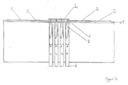
- FIG. 2 are to be picked off chips 2 on a substrate 1, z. B. an adhesive carrier film, and the chip 2 is raised in this example with 8 needles (4 needles are hidden), which lift the chip 2 of the carrier film and the chip composite.
- the ejection device is manufactured in such a way that, when the chip is lifted by means of the ejection device, the carrier material is cut through by the at least one needle during lifting.
- the front part of the needle is the part involved in the lift-off process.
- the needle tip is the foremost end of the needle through which the pressure is transferred to the chip and on which the chip rests when lifting. Next is the front part of the needle.
- the needles according to the invention can be produced from a needle blank, for example a wire pin. Any cross-sectional shapes of the wire pin may be used, e.g. round, angular or flat cross-sectional shapes.
- a needle blank for example a wire pin.
- Any cross-sectional shapes of the wire pin may be used, e.g. round, angular or flat cross-sectional shapes.
- the front part of the needle is prepared with at least one cutting edge in the part which projects beyond the original plane of the carrier foil when lifted off.
- the front part of the needle is provided with at least one edge, which serves as a cutting edge for the carrier material and is sharpened and has the smoothest possible polished surface.
- the needle can be prepared so that it tapers towards the needle tip, that is, becomes thinner.
- FIG. 3 A particularly preferred embodiment of a needle according to the invention is in FIG. 3 shown.
- This needle 4 has a triangular bevel, so that three blades 7 are formed, which cut through the substrate 1 during the lifting process.
- the front part of the needle can be prepared thinning towards the needle tip, wherein
- three side edges are prepared along at least a portion of the front part of the needle.
- the bevel with the three cutting edges results in a triangular cross-section of the needle in the front part.
- a needle is used for lifting a chip from a carrier material which is provided with three cutting edges.
- the penetration resistance of the needle into the carrier material is also greatly reduced when the needle is made of a wire pin whose diameter is less than or equal to 0.25 mm.
- Conventional needles used in the prior art have a diameter of 0.5 to 0.7 mm.
- Such a needle thickness sets the carrier film to a large surface, so that the carrier material is usually not pierced with such needles.
- the ejection device is operated with a needle having a correspondingly small diameter, so that the needle can penetrate the carrier material.
- a grinding on the front part of the needle towards the needle tip which in particular has at least one cutting edge, it was recognized here that the carrier foil is hardly lifted when the chips are lifted. Based on needle diameters of 0.25 mm, the needle tip can be worked accordingly fine.
- the ejection device can be equipped with needles depending on the chip area of the chip to be picked up.
- the chip is then after lifting as on a pincushion, like FIG. 2 also shows. This will cause the chip to stop breaking.
- a chip area of 1 mm 2 four needles are inserted into the ejection device according to the invention.
- the needle density can be increased. For example, a chip of area 1 x 1.5 mm 2 with five needles was lifted simultaneously. By using multiple needles to pick up a chip, the bending moment acting on the chip by the pressure on liftoff is reduced.
- a needle density which is at least 1 needle to 0.25 mm 2 .
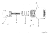
- FIGS. 4a and 4b show a specific embodiment of the ejection device.
- the ejection device is composed of a needle holder 8, in which the needles 4 can be fixed.
- the needle holder 8 of the ejector is prepared here with 12 needles.
- the needles 4 are received in holes 15 of the needle holder.
- the ejector is shown dismantled.
- the needle holder 8 is inserted via a compression spring 10 in the needle head 9 and connected.
- the grub screw 16 is used to connect the screw hole 18 in the needle holder with the slot 17 of the needle head 9.
- the compression spring 10 causes the needle head 9 and the needle holder 8 can be compressed.
- the needle head 9 and the needle holder 8 can be moved relative to each other in the assembled state.
- This has the advantage that the needle tips 5 are at rest within the needle head 9.
- the needle tips are sunk about 0.5 mm below the surface of the ejection tool, so here the needle head 9, mounted.
- the carrier film 1 moves with the wafer over the needle head 9 and so can not damage the needle tips 7.
- the needle tips 7 are pushed upwards out of the needle head 9 and act on the overlying chip 2.
- a vacuum suction port 19 can be seen, over which a hose for applying a vacuum is pushed to the vacuum holes 20 during operation of the ejection device.
- the vacuum serves to hold the carrier material by means of vacuum via the vacuum bores and thus supports the lifting process of the chip from the carrier material. The carrier material is sucked in and held by the vacuum.
- the subject of the invention is to fix the needles in the needle holder in such a way that they are not distorted during the fixing process.
- the ejection device when the ejection device is equipped with more than one needle, it is important that the Needle tips are aligned on one level.
- the mechanical forces acting on the chip by the pressure of the needles optimally distributed. Therefore, the ejector is preferably operated with needles fixed in a solidified medium.
- the prior art in the fixation of the needles in the ejection tool one-sided mechanical force expended.
- the needles in the prior art are fixed in their retaining hole by grub screws. By tightening the grub screws, the needles can easily move or distort in the hole and thus a uniform alignment of the needle tips is no longer guaranteed.
- the present invention has now recognized that it is advantageous to fix the needles via a medium which, in the solidified state, fixes the needles in the ejection device.
- this is a hot melt adhesive, which changes from the liquid to the solid state, when the temperature is changed.
- the needles are guided into the holes of the needle holder, wherein at the needle ends in the needle holder, the medium is applied, either applied in the liquid state or is liquefied after application.
- the subsequent solidification connects the needles via the medium with the needle holder. This fixes the needles firmly in the needle holder.
- the needles can be removed again using a suitable solvent. Therefore, a hot melt adhesive is particularly suitable because it can be completely removed via a solvent bath.
- a solvent eg acetone. This will dissolve the hot melt and remove the needles from the holes and reprocess the jar.
- suitable hot melt adhesive is Crystalbond 509 TM .
- FIG. 5 schematically shows a mounting device 11, which is used for introducing and fixing the needles 4 in the ejector.
- the mounting device 11 consists of a flat plate 12, on which the needle tips 5 rest during assembly, and a detachable device 13, which is attached to the ejection device for mounting, that a located in the removable device 13 recess above the needle holder. 8 is appropriate.
- the detachable device 13 is connected via the connecting piece 14 with the flat plate 12.
- the needle holder is pressed by the removable device about 0.5 mm deep on the compression spring.
- the needle holder 8 either already during insertion of the ejection device into the mounting device, - even before the introduction of the needles 4 in the holes of the needle holder 8 - are pressed by the removable device 13 on the compression spring 10 and held for further assembly . or the mounting device is used so that the ejection device is first mounted in the mounting device so that the needle holder is not yet kept pressed on the compression spring. Only when the needles 4 are already inserted into the holes 15 and only after application of the adhesive to the needle ends in Needle holder 8, the removable device 13 is moved by means of a screw or an eccentric down, it presses the needle holder 8 on the compression spring 10 of the ejector, and thereby takes by the adhesive possibly pulled upwards needles 4 again with down. This ensures even better that all the needle tips 5 rest on the flat plate 12 when the adhesive solidifies.
- the needles 4 are inserted into the bores of the ejection device.
- a needle is preferably introduced into a respective bore of the ejection device.
- the needles are loosely in the holes of the ejector and lie with their needle tips on the flat plate 12 by its own weight.
- the plate 12 serves to align the needle tip plane. Therefore, the plate 12 has a ground, very flat surface.
- the error difference of the needle tip plane is reduced by the mounting device according to the invention to a few microns.
- a hotmelt adhesive is preferably applied to the needle ends in the needle holder, the hotmelt adhesive is melted and then solidified.
- the mounting device 11 For liquefying the hot melt adhesive, the mounting device 11 is placed together with the ejector on a hot plate and heated by a hot plate to about 120 ° C.
- the mounting device consists of a good thermally conductive material, ie z.
- metallic plate metallic connector and metallic removable device.
- tool steel which also very well to a flat Plate 12 can be ground, in particular hardened tool steel.
- the hot melt adhesive is applied to the needle holder 8 and the needle ends 6 located therein via the recess which is an opening in the detachable device 13, heats and connects the needle ends 6 to the needle holder 8 and firmly fixes them upon subsequent solidification.
- the needles are firmly fixed to the tool and yet not be misaligned by the fixation.
- a hot melt adhesive which is advantageously applied as granules and is then melted.
- the mounting device is also preferably constructed so that the removable device is mounted and tightened so that the needle holder is pressed about 0.5 mm deep on the spring. The needles are then fixed. After removing the ejection device after the fixing process from the mounting device, the needles are sunk by about 0.5 mm in the ejector.
- the introduction of the needles into the ejection device can also optionally be carried out under a microscope.
- the ejector is in the assembled state of needle holder, compression spring and needle head.
- the needle head rests on a pre-assembly aid made of plastic, so that the needles come to rest with their tip on a soft plastic when introduced into the holes. This ensures that the needle tips are not injured when hitting.
- the ejection tool can now be placed upside down on the mounting device. Then the pre-assembly aid is removed. Now the Removable device as described mounted on the ejector and screwed.
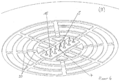
- FIG. 6 shows a prepared with needles 4 ejector, here the needle head 9 can be seen from above, and the needles 4 are pushed out.
- the holes 15 for the needles in the needle head 9 can be seen.
- the holes 15 are approximately 0.27 mm in diameter.
- vacuum holes 20 vacuum flows during the lifting process of the chip from the carrier material to the carrier material and the carrier material is thereby held on the needle head.
- FIG. 7 shows the preparation of a needle according to the invention, in the front part of the needle with three cutting edges (one hidden), which are carved out as pointed, wedge-shaped side edges, and tapers towards the tip of the needle, so that the tip is pointed out accordingly ,
- the carrier material first pierced and then, by the further pressure of the needle and thus the high pressure forces the cutting edge against the carrier material of this cut by the cutting Starting the needle up to the point where the chip is presented for picking by the pickup tool.
- the pressure against the carrier material or against the carrier film by pressing the needle against the carrier material and against the chip is thus taken by the cutting of the carrier film, so that it does not bend or is raised further, and thus even little pressure on the chip itself and no slippage of the adjacent chips leads to chip damage.
- the carrier film is completely detached from the chip, so that when picking up the chip by the picking tool no Restadpiansions will hold the chip.
- the side edges 7 are drawn on the drawing as a straight side edges. These can also be curved arcuately outward or curved inwards.
- the side surface 21 between two cutting edges can be worked as a straight surface between the two cutting edges. However, the side surface 21 may also be ground in a curved manner between the side edges. In order to increase the sharpness of the side edges, the side surface may in particular be arcuately inwardly ground.
- the length of the needles used here is 29 mm. However, this is to be adjusted depending on the ejector and the production machine and is typically between 10 mm and 30 mm.
- the state of the art works with conical tips. According to the invention sharpened side edges are now ground along the front part of the needle.
- the three cutting edges are ground from a wire blank at an angle ⁇ .
- This angle can be about 120 °, but can also deviate from it, so that the three cutting edges are not at the same angular distance from each other.
- the preferred diameter from which the needle is ground is less than or equal to 0.25 mm.
- the respective angle ⁇ between height h and side edge or cutting edge 7 can be chosen arbitrarily.
- the height h is the perpendicular which is cut from the needle point to the base plane, wherein the base plane is the cross-sectional area at the needle end 6.
- a preferred selected angle ⁇ is 4 ° to 8 ° here.
Landscapes
- Container, Conveyance, Adherence, Positioning, Of Wafer (AREA)
- Automatic Assembly (AREA)
Applications Claiming Priority (1)
| Application Number | Priority Date | Filing Date | Title |
|---|---|---|---|
| DE102012013370.7A DE102012013370B4 (de) | 2012-07-04 | 2012-07-04 | Montagevorrichtung und Verfahren zum Fixieren einer Nadel in einem Nadelhalter einer Ausstoßvorrichtung zum Abheben eines Chips von einem Trägermaterial |
Publications (2)
| Publication Number | Publication Date |
|---|---|
| EP2682981A2 true EP2682981A2 (fr) | 2014-01-08 |
| EP2682981A3 EP2682981A3 (fr) | 2014-03-05 |
Family
ID=48607095
Family Applications (1)
| Application Number | Title | Priority Date | Filing Date |
|---|---|---|---|
| EP13170752.3A Withdrawn EP2682981A3 (fr) | 2012-07-04 | 2013-06-06 | Dispositif d'éjection pour l'enlèvement d'une puce sur un matériau de support |
Country Status (3)
| Country | Link |
|---|---|
| US (1) | US20140008017A1 (fr) |
| EP (1) | EP2682981A3 (fr) |
| DE (1) | DE102012013370B4 (fr) |
Cited By (1)
| Publication number | Priority date | Publication date | Assignee | Title |
|---|---|---|---|---|
| CN112967985A (zh) * | 2020-09-28 | 2021-06-15 | 重庆康佳光电技术研究院有限公司 | 转移结构及其制作方法、芯片转移方法、显示面板及装置 |
Families Citing this family (10)
| Publication number | Priority date | Publication date | Assignee | Title |
|---|---|---|---|---|
| US20160167948A1 (en) * | 2014-12-15 | 2016-06-16 | W. L. Gore & Associates, Inc. | Vent Attachment System For Micro-Electromechanical Systems |
| US9633883B2 (en) | 2015-03-20 | 2017-04-25 | Rohinni, LLC | Apparatus for transfer of semiconductor devices |
| EP3234992B1 (fr) * | 2016-01-29 | 2018-09-26 | JENOPTIK Optical Systems GmbH | Méthode et appareil pour détacher une micro-puce d'une plaquette et placement de la micro-puce sur un substrat |
| US10141215B2 (en) | 2016-11-03 | 2018-11-27 | Rohinni, LLC | Compliant needle for direct transfer of semiconductor devices |
| US10504767B2 (en) | 2016-11-23 | 2019-12-10 | Rohinni, LLC | Direct transfer apparatus for a pattern array of semiconductor device die |
| US10471545B2 (en) | 2016-11-23 | 2019-11-12 | Rohinni, LLC | Top-side laser for direct transfer of semiconductor devices |
| US10410905B1 (en) * | 2018-05-12 | 2019-09-10 | Rohinni, LLC | Method and apparatus for direct transfer of multiple semiconductor devices |
| US11232968B2 (en) * | 2018-09-28 | 2022-01-25 | Rohinni, LLC | Variable pitch multi-needle head for transfer of semiconductor devices |
| US11094571B2 (en) | 2018-09-28 | 2021-08-17 | Rohinni, LLC | Apparatus to increase transferspeed of semiconductor devices with micro-adjustment |
| CN115662937B (zh) * | 2022-12-29 | 2023-03-17 | 四川晶辉半导体有限公司 | 一种芯片安装设备 |
Family Cites Families (8)
| Publication number | Priority date | Publication date | Assignee | Title |
|---|---|---|---|---|
| DE59204509D1 (de) | 1992-04-13 | 1996-01-11 | Tresky Dr Ing Miroslav | Ausstossvorrichtung zum Abtrennen eines Chips von einem adhäsiven Träger. |
| JPH06275704A (ja) * | 1993-03-17 | 1994-09-30 | Deisuko Eng Service:Kk | 半導体チップ突き上げ針の製造方法及びその製造用治具 |
| KR100278137B1 (ko) * | 1997-09-04 | 2001-01-15 | 가나이 쓰도무 | 반도체소자의 탑재방법 및 그 시스템, 반도체소자 분리장치 및ic카드의 제조방법 |
| US6283693B1 (en) * | 1999-11-12 | 2001-09-04 | General Semiconductor, Inc. | Method and apparatus for semiconductor chip handling |
| DE10122437A1 (de) * | 2001-05-09 | 2002-11-28 | Henkel Kgaa | Schmelzklebstoff in Form eines Granulates |
| US6889427B2 (en) * | 2002-02-15 | 2005-05-10 | Freescale Semiconductor, Inc. | Process for disengaging semiconductor die from an adhesive film |
| JP2006344657A (ja) * | 2005-06-07 | 2006-12-21 | Fujifilm Holdings Corp | チップのピックアップ装置及びその使用方法 |
| WO2009056469A1 (fr) * | 2007-10-31 | 2009-05-07 | Oerlikon Assembly Equipment Ag, Steinhausen | Aiguille à perforer une feuille pour en détacher un petit dé |
-
2012
- 2012-07-04 DE DE102012013370.7A patent/DE102012013370B4/de not_active Expired - Fee Related
-
2013
- 2013-06-06 EP EP13170752.3A patent/EP2682981A3/fr not_active Withdrawn
- 2013-06-28 US US13/930,750 patent/US20140008017A1/en not_active Abandoned
Cited By (2)
| Publication number | Priority date | Publication date | Assignee | Title |
|---|---|---|---|---|
| CN112967985A (zh) * | 2020-09-28 | 2021-06-15 | 重庆康佳光电技术研究院有限公司 | 转移结构及其制作方法、芯片转移方法、显示面板及装置 |
| CN112967985B (zh) * | 2020-09-28 | 2022-04-19 | 重庆康佳光电技术研究院有限公司 | 转移结构及其制作方法、芯片转移方法、显示面板及装置 |
Also Published As
| Publication number | Publication date |
|---|---|
| US20140008017A1 (en) | 2014-01-09 |
| EP2682981A3 (fr) | 2014-03-05 |
| DE102012013370B4 (de) | 2017-11-23 |
| DE102012013370A1 (de) | 2014-01-09 |
Similar Documents
| Publication | Publication Date | Title |
|---|---|---|
| DE102012013370B4 (de) | Montagevorrichtung und Verfahren zum Fixieren einer Nadel in einem Nadelhalter einer Ausstoßvorrichtung zum Abheben eines Chips von einem Trägermaterial | |
| DE60316575T2 (de) | Verfahren und vorrichtung zum aufnehmen von halbleiterchips sowie dazu verwendbares saugung ablöswerkzeug | |
| WO2008003502A1 (fr) | Dispositif et procédé pour individualiser et transporter des substrats | |
| EP2359398B1 (fr) | Procédé pour détacher et prélever une puce de semi-conducteur sur un film | |
| EP2303488A1 (fr) | Procédé et dispositif pour la production de pièces découpées de précision à partir d'une bande de matériau | |
| DE10146936B4 (de) | Herstellverfahren für eine Chipkomponenten-Baugruppe | |
| EP1587138B1 (fr) | Dispositif pour la montage de de puces semiconductrices et procédé de séparer de puces semiconductries d'une feuille | |
| DE19947015B4 (de) | Verfahren zum Schneiden und Trennen einer gebogenen CSP-Platte mit erheblicher Biegung in einzelne kleine Teile | |
| DE60219795T2 (de) | Einrichtung zum entfernen der beschichtung eines lichtwellenleiters | |
| EP1449415B1 (fr) | Procede et dispositif de metallisation de substrats et plaquettes | |
| DE112015005680T5 (de) | Wafergruppe, Waferherstellungsvorrichtung und Waferherstellungsverfahren | |
| DE19916071B4 (de) | Verfahren zum Vereinzeln von Halbleiterbauelementen und Trennvorrichtung | |
| DE102006059809B4 (de) | Vorrichtung und Verfahren zum Vereinzeln und Transportieren von Substraten | |
| DE102018125682B4 (de) | Ejektorvorrichtung sowie Verfahren zum Unterstützen eines Ablösens eines auf einer Haltefolie angeordneten elektrischen Bauteils | |
| DE102015100827B4 (de) | Verfahren zum Bearbeiten eines Halbleitersubstrats | |
| WO2005083779A1 (fr) | Plaquette semi-conductrice fine enduite au dos et procede de realisation associe | |
| DE102013012225A1 (de) | Verfahren zur TEM-Lamellen-Herstellung und Anordnung für TEM-Lamellen-Schutzvorrichtung | |
| DE19840388B4 (de) | Vorrichtung zum Positionieren und Vereinzeln einer Vielzahl von mittels einer Trägerschicht verbundenen Mikroabformteilen | |
| EP3886149A1 (fr) | Dispositif et procédé de liaison de substrats | |
| EP3695944B1 (fr) | Procédé et dispositif de division des objets en forme de plaque de matériaux friables | |
| EP3675153A1 (fr) | Procédé de fabrication d'un adaptateur de substrat et adaptateur de substrat destiné au raccordement à un composant électronique | |
| EP1935599B1 (fr) | Dispositif et procédé pour la séparation et le transport de substrats | |
| DE102005048153B4 (de) | Verfahren zur Herstellung eines Halbleiterbauteils mit Halbleiterchip und Klebstofffolie | |
| DE102018216198A1 (de) | Halbleiter-Aufnahmevorrichtung | |
| DE102020210751A1 (de) | Verfahren zum entfernen einer trägerplatte |
Legal Events
| Date | Code | Title | Description |
|---|---|---|---|
| PUAI | Public reference made under article 153(3) epc to a published international application that has entered the european phase |
Free format text: ORIGINAL CODE: 0009012 |
|
| AK | Designated contracting states |
Kind code of ref document: A2 Designated state(s): AL AT BE BG CH CY CZ DE DK EE ES FI FR GB GR HR HU IE IS IT LI LT LU LV MC MK MT NL NO PL PT RO RS SE SI SK SM TR |
|
| AX | Request for extension of the european patent |
Extension state: BA ME |
|
| PUAL | Search report despatched |
Free format text: ORIGINAL CODE: 0009013 |
|
| AK | Designated contracting states |
Kind code of ref document: A3 Designated state(s): AL AT BE BG CH CY CZ DE DK EE ES FI FR GB GR HR HU IE IS IT LI LT LU LV MC MK MT NL NO PL PT RO RS SE SI SK SM TR |
|
| AX | Request for extension of the european patent |
Extension state: BA ME |
|
| RIC1 | Information provided on ipc code assigned before grant |
Ipc: H01L 21/67 20060101AFI20140130BHEP |
|
| STAA | Information on the status of an ep patent application or granted ep patent |
Free format text: STATUS: THE APPLICATION IS DEEMED TO BE WITHDRAWN |
|
| 18D | Application deemed to be withdrawn |
Effective date: 20140906 |