EP2683049A2 - Generatorverwaltungssystem zur selektiven Trennung von Brennstoff an einen Generator zum Hinzufügen einer Last zu einem Bus - Google Patents
Generatorverwaltungssystem zur selektiven Trennung von Brennstoff an einen Generator zum Hinzufügen einer Last zu einem Bus Download PDFInfo
- Publication number
- EP2683049A2 EP2683049A2 EP13003305.3A EP13003305A EP2683049A2 EP 2683049 A2 EP2683049 A2 EP 2683049A2 EP 13003305 A EP13003305 A EP 13003305A EP 2683049 A2 EP2683049 A2 EP 2683049A2
- Authority
- EP
- European Patent Office
- Prior art keywords
- generator
- bus
- management system
- load
- generators
- Prior art date
- Legal status (The legal status is an assumption and is not a legal conclusion. Google has not performed a legal analysis and makes no representation as to the accuracy of the status listed.)
- Ceased
Links
Images


Classifications
-
- H—ELECTRICITY
- H02—GENERATION; CONVERSION OR DISTRIBUTION OF ELECTRIC POWER
- H02J—ELECTRIC POWER NETWORKS; CIRCUIT ARRANGEMENTS OR SYSTEMS FOR SUPPLYING OR DISTRIBUTING ELECTRIC POWER; SYSTEMS FOR STORING ELECTRIC ENERGY
- H02J3/00—Circuit arrangements for AC mains or AC distribution networks
- H02J3/38—Arrangements for feeding a single network from two or more generators or sources in parallel; Arrangements for feeding already energised networks from additional generators or sources in parallel
-
- H—ELECTRICITY
- H02—GENERATION; CONVERSION OR DISTRIBUTION OF ELECTRIC POWER
- H02J—ELECTRIC POWER NETWORKS; CIRCUIT ARRANGEMENTS OR SYSTEMS FOR SUPPLYING OR DISTRIBUTING ELECTRIC POWER; SYSTEMS FOR STORING ELECTRIC ENERGY
- H02J3/00—Circuit arrangements for AC mains or AC distribution networks
-
- H—ELECTRICITY
- H02—GENERATION; CONVERSION OR DISTRIBUTION OF ELECTRIC POWER
- H02J—ELECTRIC POWER NETWORKS; CIRCUIT ARRANGEMENTS OR SYSTEMS FOR SUPPLYING OR DISTRIBUTING ELECTRIC POWER; SYSTEMS FOR STORING ELECTRIC ENERGY
- H02J9/00—Circuit arrangements for emergency or stand-by power supply, e.g. for emergency lighting
- H02J9/04—Circuit arrangements for emergency or stand-by power supply, e.g. for emergency lighting in which the distribution system is disconnected from the normal source and connected to a standby source
- H02J9/06—Circuit arrangements for emergency or stand-by power supply, e.g. for emergency lighting in which the distribution system is disconnected from the normal source and connected to a standby source with automatic change-over, e.g. UPS systems
- H02J9/08—Circuit arrangements for emergency or stand-by power supply, e.g. for emergency lighting in which the distribution system is disconnected from the normal source and connected to a standby source with automatic change-over, e.g. UPS systems requiring starting of a prime-mover
-
- G—PHYSICS
- G01—MEASURING; TESTING
- G01R—MEASURING ELECTRIC VARIABLES; MEASURING MAGNETIC VARIABLES
- G01R31/00—Arrangements for testing electric properties; Arrangements for locating electric faults; Arrangements for electrical testing characterised by what is being tested not provided for elsewhere
- G01R31/34—Testing dynamo-electric machines
-
- H—ELECTRICITY
- H02—GENERATION; CONVERSION OR DISTRIBUTION OF ELECTRIC POWER
- H02H—EMERGENCY PROTECTIVE CIRCUIT ARRANGEMENTS
- H02H7/00—Emergency protective circuit arrangements specially adapted for specific types of electric machines or apparatus or for sectionalised protection of cable or line systems, and effecting automatic switching in the event of an undesired change from normal working conditions
- H02H7/06—Emergency protective circuit arrangements specially adapted for specific types of electric machines or apparatus or for sectionalised protection of cable or line systems, and effecting automatic switching in the event of an undesired change from normal working conditions for dynamo-electric generators; for synchronous capacitors
- H02H7/062—Emergency protective circuit arrangements specially adapted for specific types of electric machines or apparatus or for sectionalised protection of cable or line systems, and effecting automatic switching in the event of an undesired change from normal working conditions for dynamo-electric generators; for synchronous capacitors for parallel connected generators
Definitions
- Embodiments pertain to a generator management system, and more particularly to a generator management system that selectively cuts off fuel to a generator to add a load to a bus.
- Electric generators are typically used to provide electrical power.
- One common use of electric generators is as a standby power source.
- One common type of electric generator includes an internal combustion engine.
- the internal combustion engine drives an electrical alternator that produces alternating electricity.
- One of the advantages is that if one generator fails, or requires maintenance, a multi-generator system can still supply some power while a single generator system would otherwise not be able to meet demand. Another advantage is that load growth may be addressed by adding another generator rather than replacing an existing generator with a larger (and more expensive) generator.
- Another advantage of using multiple smaller generators is that they can be tested individually. Therefore, these multiple smaller generators can be tested using relatively smaller loads.
- a load is required during testing to (i) avoid an accumulation of unburned fuel within the exhaust system of a generator; (ii) to activate a catalyst to minimize air pollution; and (iii) verify load carrying ability of a generator.
- An external load is typically provided for testing by (i) transferring site load to the standby source, or (ii) using a resistive load bank.
- Transferring site load to the standby source is undesirable because it often results in a brief interruption of power to the site.
- transferring site load to the standby source is undesirable because any failures during a test can result in a loss of power to the site.
- Providing a resistive load bank for testing the standby generators is undesirable because it adds additional required maintenance.
- providing a resistive load bank adds unwanted cost and takes up space.
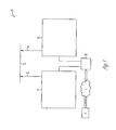
- FIG. 1 is a schematic plan view of an example generator management system before the generator management system selectively cuts off fuel to a generator to add a load to a bus.
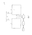
- FIG. 2 shows the generator management system of FIG. 1 after the generator management system has selectively cut off fuel to a generator to add the load to a bus.
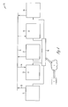
- FIG. 3 shows the generator management system of FIG. I where the generator management system includes additional generators.
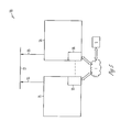
- FIG. 4 shows the generator management system of FIG. 3 after the generator management system has selectively cuts off fuel to a plurality of generators to add loads to the bus.
- FIG. 5 is a schematic plan view of another example generator management system before the generator management system selectively cuts off fuel to a generator to add a load to a bus.
- FIG. 6 shows the generator management system of FIG. 5 after the generator management system has selectively cut off fuel to a generator to add a load to the bus.
- FIG. 7 shows the generator management system of FIG. 5 where the generator management system includes additional generators.
- FIG. 8 shows the generator management system of FIG. 7 after the generator management system has selectively cuts off fuel to a plurality of generators to add loads to the bus.
- FIG. 1 is a schematic plan view of an example generator management system 10.
- the generator management system 10 includes a first generator 11 having a first set of power leads 12 and a second generator 13 having a second set of power leads 14.
- the generator management system 10 further includes a bus 15 that connects the first output 12 and the second output 14.
- a controller 16 selectively cuts off fuel to the second generator 13 to add a load L1 to the bus 15 (see FIG. 2 ). It should be noted that embodiments are contemplated where the generator management system 10 alternatively cuts off fuel to the first generator 11 to add a load to the bus 15.
- FIG. I shows the generator management system 10 before the generator management system 10 selectively cuts off fuel to at least one of the first generator 11 and the second generator 13. Power may be supplied to the bus 15 by the first generator 11 through power leads 12 and/or the second generator 13 through power leads 14.
- FIG. 2 shows the generator management system 10 after the generator management system 10 has selectively cut off fuel to second generator 13 to provide a load L1 to the bus 15. Power is supplied from the first generator 11 to the load L1 through power leads 12, the bus 15 and power leads 14.
- FIG. 3 shows an example embodiment of the generator management system 10 where the first generator 11 and the second generator 13 are part of a plurality of additional generators 17, 18, 19 that are connected to the bus 15. All of the generators 11, 13, 17, 18, 19 are supplying power to the bus 15 through their respective power leads.
- FIG. 4 shows the example embodiment of FIG 3 after the controller 16 selectively cuts off fuel to at least one of the plurality of additional generators to provide load L1, L2 to the bus 15. As shown, fuel is cut off to generator 13 and generator 18 and power is supplied from generators 11, 17, 19 to the loads L1, L2 through the respective power leads and the bus 15.
- controller 16 may cut off fuel to any individual generator or combination of the generators 11, 13, 17, 18, 19 in order to add load(s) to the bus 15.
- controller 16 selectively cuts off fuel to any number of generators, where the number of generators with fuel cut off is dependent on a minimum bus load requirement.
- the minimum bus load requirement may be determined based on local emission standards.
- the minimum bus load requirement may be determined based on a minimum engine exhaust temperature of at least one of the plurality of generators 11, 13, 17, 18, 19 that is supplying power to the loads.
- At least one of the plurality of generators 11, 13, 17, 18, 19 may include a diesel engine that has a particulate filter.
- the generator management system 10 includes one or more diesel engines that have a particulate filter, the minimum bus load requirement may depend on scheduled regeneration of one or more the particulate filters.
- the generator management system 10 may further include a server S that is connected to the controller 16 via a network (e.g., the Internet I).
- a network e.g., the Internet I.
- the generator management system 10 includes a server S
- at least one of the controller 16 and the server S may selectively cut off fuel to any of the generators 11, 13, 17, 18, 19 to add a load to the bus 15.
- FIG. 5 is a schematic plan view of another example generator management system 20.
- the generator management system 20 includes a first generator 21 having a first set of power leads 22.
- a first generator controller 23 operates the first generator 21.
- the generator management system 20 further includes a second generator 24 having a second set of power leads 25.
- a second generator controller 26 operates the second generator 24.
- the generator management system 20 further includes a parallel bus 27 that connects the first set of power leads 22 and the second set of power leads 25.
- FIG. 5 shows the generator management system 20 before at least one of the first generator controller 23 and the second generator controller 26 selectively cuts off fuel to the second generator 24.
- the first generator 21 may supply power to the bus 15 through power leads 22 and the second generator 24 may supply power to the bus 15 through power leads 25.
- FIG. 6 shows the generator management system 20 after at least one of the first generator controller 23 and the second generator controller 26 has selectively cut off fuel to second generator 24 to add a load L3 to the parallel bus 27. Therefore, power is supplied from the first generator 21 to the load L3 through power leads 22, the bus 27 and power leads 25.
- FIG. 7 shows an example embodiment of the generator management system 20 where the first generator 21 and the second generator 24 are part of a plurality of additional generators 28, 31, 34. All of the generators 21, 24, 28, 31, 34 are supplying power to the bus 27 through their respective power leads. It should be noted that each of the additional generators 28, 31, 34 that are connected to the parallel bus 27 may (or may not) include a generator controller. FIG. 7 shows an example embodiment where each of the additional generators 28, 31, 34 include a respective generator controller 29, 32, 35.
- FIG. 8 shows the example embodiment of FIG. 7 after at least one the respective generator controllers 23, 26, 29, 32, 35 selectively cuts off fuel to at least one of the plurality of generators 21, 24, 28, 31, 34.
- fuel is cut off to generator 24 and generator 31 and power is supplied from generators 21, 28, 34 to the loads L3, L4 through the respective power leads and the bus 27.
- fuel is cut off to second generator 24 and one of the additional generators 32 in the example embodiment illustrated in FIG. 8
- at least one the respective generator controllers 23, 26, 29, 32, 35 may cut off fuel to any individual generator or combination of the generators 21, 24, 28, 31, 34 in order to add load(s) to the parallel bus 27.
- at least one (or more) of the respective generator controllers 23, 26, 29, 32, 35 selectively cuts off fuel to any number of generators, where the number of generators with fuel cut off is dependent on a minimum bus load requirement.
- the minimum bus load requirement may be determined based on local emission standards.
- the minimum bus load requirement may be determined based on a minimum engine exhaust temperature of at least one of the plurality of generators 21, 24, 28, 31, 34 that is supplying power to the loads,
- At least one of the plurality of generators 21, 24, 28, 31, 34 may include a diesel engine that has a particulate filter.
- the generator management system 20 includes one or more diesel engines that have a particulate filter, the minimum bus load requirement may depend on scheduled regeneration of one or more the particulate filters.
- the generator management system 20 may further include a server S that is connected to one, some or all of the respective generator controllers 23, 26, 29, 32, 35 via a network (e.g., the Internet I).
- a network e.g., the Internet I.
- the generator management system 10 includes a server S
- none, one, some or all of the respective generator controllers 23, 26, 29, 32, 35 and/or the server S may selectively cut off fuel to any of the generators 21, 24, 28, 31, 34 to add a load(s) to the parallel bus 27.
- the generator management systems 10, 20 described herein may reduce the need to provide an external load for testing of generators.
- generator management systems 10, 20 may permit testing of generators without interruption of power to the site.
Landscapes
- Engineering & Computer Science (AREA)
- Power Engineering (AREA)
- Business, Economics & Management (AREA)
- Emergency Management (AREA)
- Supply And Distribution Of Alternating Current (AREA)
- Control Of Vehicle Engines Or Engines For Specific Uses (AREA)
- Hybrid Electric Vehicles (AREA)
Applications Claiming Priority (1)
| Application Number | Priority Date | Filing Date | Title |
|---|---|---|---|
| US13/540,146 US8963349B2 (en) | 2012-07-02 | 2012-07-02 | Generator management system that selectively cuts off fuel to a generator to add a load to a bus |
Publications (2)
| Publication Number | Publication Date |
|---|---|
| EP2683049A2 true EP2683049A2 (de) | 2014-01-08 |
| EP2683049A3 EP2683049A3 (de) | 2016-05-11 |
Family
ID=48803357
Family Applications (1)
| Application Number | Title | Priority Date | Filing Date |
|---|---|---|---|
| EP13003305.3A Ceased EP2683049A3 (de) | 2012-07-02 | 2013-06-28 | Generatorverwaltungssystem zur selektiven Trennung von Brennstoff an einen Generator zum Hinzufügen einer Last zu einem Bus |
Country Status (5)
| Country | Link |
|---|---|
| US (1) | US8963349B2 (de) |
| EP (1) | EP2683049A3 (de) |
| CN (1) | CN103532171B (de) |
| BR (1) | BR102013016816A2 (de) |
| IN (1) | IN2013MU02170A (de) |
Families Citing this family (4)
| Publication number | Priority date | Publication date | Assignee | Title |
|---|---|---|---|---|
| US9698625B2 (en) | 2012-07-02 | 2017-07-04 | Kohler Co. | Power generation system with anticipatory operation |
| US9368972B2 (en) | 2012-07-27 | 2016-06-14 | Kohler Co. | Generator management system that determines a time to activate and deactivate generators based on the load level |
| US9467080B2 (en) | 2014-08-13 | 2016-10-11 | Kohler, Co. | Protective functions for parallel generators |
| US10146242B2 (en) | 2016-08-25 | 2018-12-04 | Caterpillar Inc. | Micro grid power system |
Citations (1)
| Publication number | Priority date | Publication date | Assignee | Title |
|---|---|---|---|---|
| US20120068541A1 (en) * | 2010-09-20 | 2012-03-22 | Eaton Corporation | Power supply systems and methods employing a ups interfaced generator |
Family Cites Families (37)
| Publication number | Priority date | Publication date | Assignee | Title |
|---|---|---|---|---|
| US2832896A (en) | 1955-07-11 | 1958-04-29 | Boeing Co | Alternator overload protection |
| US3300647A (en) | 1963-10-28 | 1967-01-24 | Trw Inc | Alternator load demand sequencing system |
| US3489914A (en) | 1965-08-12 | 1970-01-13 | Ready Power Co | Electrical generating system |
| US4233555A (en) | 1979-04-05 | 1980-11-11 | Dyna Technology, Inc. | Alternating current generator for providing three phase and single phase power at different respective voltages |
| US4405892A (en) | 1979-07-19 | 1983-09-20 | Brunswick Corporation | Regulator for a generator energized battery |
| US4302683A (en) | 1980-03-07 | 1981-11-24 | Burton Von L | Reaction engine driven electrical generating system with power load variation control capability |
| IT1139075B (it) | 1981-04-06 | 1986-09-17 | Alfa Romeo Auto Spa | Apparato di controllo dell'alimentazione per un motore a c.i. |
| US4625123A (en) | 1984-09-24 | 1986-11-25 | Onan Corporation | Load sensitive fuel cutoff and method to increase engine stability |
| US5252905A (en) | 1985-12-23 | 1993-10-12 | York International Corporation | Driving system for single phase A-C induction motor |
| JPH01200056A (ja) | 1988-02-03 | 1989-08-11 | Fuji Heavy Ind Ltd | エンジンの燃料不足検出装置 |
| JP2528995B2 (ja) | 1990-03-19 | 1996-08-28 | 株式会社日立製作所 | 車載発電機の制御システム |
| GB9408678D0 (en) | 1994-04-30 | 1994-06-22 | Aisin Seiki | Gas turbine engine driven auxilliary electric power unit |
| US5625276A (en) | 1994-09-14 | 1997-04-29 | Coleman Powermate, Inc. | Controller for permanent magnet generator |
| JP3489106B2 (ja) | 1994-12-08 | 2004-01-19 | 株式会社サタケ | ブラシレス三相同期発電機 |
| JP3248827B2 (ja) | 1995-01-18 | 2002-01-21 | 三菱電機株式会社 | エンジン発電機の制御装置 |
| JP3730286B2 (ja) | 1995-07-12 | 2005-12-21 | 富士重工業株式会社 | エンジン停止装置 |
| JPH09195811A (ja) * | 1996-01-19 | 1997-07-29 | Komatsu Ltd | 発電機の自動負荷分担装置及びその制御方法 |
| US5754033A (en) * | 1996-03-13 | 1998-05-19 | Alaska Power Systems Inc. | Control system and circuits for distributed electrical-power generating stations |
| DE69738593T2 (de) | 1996-06-24 | 2009-04-23 | Sanyo Electric Co., Ltd., Moriguchi | Stromversorgungssystem mit Systemverbindung |
| US6191500B1 (en) | 1998-11-06 | 2001-02-20 | Kling Lindquist Partnership, Inc. | System and method for providing an uninterruptible power supply to a critical load |
| DE10104892A1 (de) * | 2001-02-01 | 2002-08-14 | Siemens Ag | Schiffs-Elektrosystem |
| US6844706B2 (en) | 2002-08-30 | 2005-01-18 | Active Power, Inc. | Multiple path variable speed constant frequency device having automatic power path selection capability |
| US6923168B2 (en) | 2003-02-10 | 2005-08-02 | Power-One As | Fuel control system and method for distributed power generation, conversion, and storage system |
| JP2004257285A (ja) | 2003-02-25 | 2004-09-16 | Honda Motor Co Ltd | エンジン駆動式発電装置 |
| CN1332500C (zh) | 2005-02-04 | 2007-08-15 | 艾纯 | 小型二极单相发电机 |
| US7151332B2 (en) | 2005-04-27 | 2006-12-19 | Stephen Kundel | Motor having reciprocating and rotating permanent magnets |
| FR2892574A1 (fr) | 2005-10-20 | 2007-04-27 | Leroy Somer Moteurs | Dispositif de controle d'un groupe electrogene |
| WO2008130968A1 (en) * | 2007-04-19 | 2008-10-30 | Glacier Bay, Inc. | Power generation system for marine vessel |
| GB0806492D0 (en) * | 2008-04-10 | 2008-05-14 | Rolls Royce Plc | A generating system |
| JP5282731B2 (ja) | 2009-12-22 | 2013-09-04 | 株式会社安川電機 | 電力変換装置 |
| US8604630B2 (en) | 2010-06-01 | 2013-12-10 | Caterpillar Inc. | Power distribution system having priority load control |
| US9006930B2 (en) | 2010-07-08 | 2015-04-14 | Delta Electronics Inc. | Power supply having converters with serially connected inputs and parallel connected outputs |
| CN102307036B (zh) | 2011-03-15 | 2013-06-19 | 隆鑫通用动力股份有限公司 | 一种内燃机驱动发电机组并联运行的控制方法和装置 |
| JP2012204571A (ja) | 2011-03-25 | 2012-10-22 | Toshiba Corp | 発電システム監視装置およびコンピュータプログラム |
| CN102185340A (zh) * | 2011-04-06 | 2011-09-14 | 上海恩艾思电气有限公司 | 船舶功率管理系统 |
| CN102353901A (zh) * | 2011-06-30 | 2012-02-15 | 无锡星诺电气有限公司 | 发电机测试系统 |
| US9368972B2 (en) | 2012-07-27 | 2016-06-14 | Kohler Co. | Generator management system that determines a time to activate and deactivate generators based on the load level |
-
2012
- 2012-07-02 US US13/540,146 patent/US8963349B2/en active Active
-
2013
- 2013-06-26 IN IN2170MU2013 patent/IN2013MU02170A/en unknown
- 2013-06-28 BR BRBR102013016816-5A patent/BR102013016816A2/pt not_active Application Discontinuation
- 2013-06-28 EP EP13003305.3A patent/EP2683049A3/de not_active Ceased
- 2013-07-01 CN CN201310271829.0A patent/CN103532171B/zh not_active Expired - Fee Related
Patent Citations (1)
| Publication number | Priority date | Publication date | Assignee | Title |
|---|---|---|---|---|
| US20120068541A1 (en) * | 2010-09-20 | 2012-03-22 | Eaton Corporation | Power supply systems and methods employing a ups interfaced generator |
Also Published As
| Publication number | Publication date |
|---|---|
| IN2013MU02170A (de) | 2015-06-12 |
| CN103532171B (zh) | 2016-09-21 |
| US8963349B2 (en) | 2015-02-24 |
| US20140001769A1 (en) | 2014-01-02 |
| BR102013016816A2 (pt) | 2015-07-28 |
| CN103532171A (zh) | 2014-01-22 |
| EP2683049A3 (de) | 2016-05-11 |
Similar Documents
| Publication | Publication Date | Title |
|---|---|---|
| EP2683078A2 (de) | Generatorverwaltungssystem, das Generatoren basierend auf einem Betriebsparameter selektiv aktiviert | |
| EP2706645B1 (de) | Stromerzeugungssystem mit mehreren parallel geschalteten Ladegeräten, das den Strom zum Aufladen von Batterien optimiert | |
| EP2683049A2 (de) | Generatorverwaltungssystem zur selektiven Trennung von Brennstoff an einen Generator zum Hinzufügen einer Last zu einem Bus | |
| US20140028102A1 (en) | Generator management system that determines a time to activate and deactivate generators based on the load level | |
| US20160282231A1 (en) | Blended service schedule for a power generator | |
| DE102016008047A1 (de) | Steuersystem und Steuerstrategie für einen Generatorsatz | |
| CN104977862B (zh) | 选择性激活发电系统中的多个发电机中的至少一个的发电机管理系统和方法 | |
| US8829855B2 (en) | Power generation system that optimizes the power provided to start a generator | |
| US9548612B2 (en) | Paralleling module for a generator system | |
| US9871378B2 (en) | Paralleling module for a generator system | |
| CN104484772B (zh) | 电量计划的可行性校验方法和系统 | |
| CN105932701A (zh) | 一种抽水蓄能多机组共享sfc启动厂用电电源优化配置方法 | |
| US20140136001A1 (en) | Device and method for distributing power at a remote pumping system | |
| Hopkins et al. | Gas powered engines with energy storage-a game changer in land drilling | |
| CN103633729A (zh) | 数据中心机房配电系统 | |
| EP3459154A1 (de) | Energieversorgungssystem für ein inselnetz | |
| US20200095970A1 (en) | Solid state power supply configuration for multiple engine systems | |
| CN104868589A (zh) | 一种分段式供电装置和方法 | |
| CN109552345A (zh) | 一种双内燃机组的机车电路及机车控制系统 | |
| US20090025678A1 (en) | Trinity pneumatic energy systems | |
| EP3130050B1 (de) | Steuereinheit für ein antriebsaggregat | |
| RU166901U1 (ru) | Дизель-генераторная установка, содержащая высоконадежную цепь стартера | |
| Drake et al. | Diesel gensets boost Grand Cayman capacity | |
| Wagner | ENERGY CRUNCH: Army powers up for ambitious fuel saving program |
Legal Events
| Date | Code | Title | Description |
|---|---|---|---|
| PUAI | Public reference made under article 153(3) epc to a published international application that has entered the european phase |
Free format text: ORIGINAL CODE: 0009012 |
|
| AK | Designated contracting states |
Kind code of ref document: A2 Designated state(s): AL AT BE BG CH CY CZ DE DK EE ES FI FR GB GR HR HU IE IS IT LI LT LU LV MC MK MT NL NO PL PT RO RS SE SI SK SM TR |
|
| AX | Request for extension of the european patent |
Extension state: BA ME |
|
| PUAL | Search report despatched |
Free format text: ORIGINAL CODE: 0009013 |
|
| AK | Designated contracting states |
Kind code of ref document: A3 Designated state(s): AL AT BE BG CH CY CZ DE DK EE ES FI FR GB GR HR HU IE IS IT LI LT LU LV MC MK MT NL NO PL PT RO RS SE SI SK SM TR |
|
| AX | Request for extension of the european patent |
Extension state: BA ME |
|
| RIC1 | Information provided on ipc code assigned before grant |
Ipc: H02H 7/06 20060101ALN20160401BHEP Ipc: H02J 3/46 20060101ALI20160401BHEP Ipc: H02J 3/38 20060101AFI20160401BHEP Ipc: G01R 31/34 20060101ALN20160401BHEP Ipc: H02J 9/08 20060101ALI20160401BHEP |
|
| STAA | Information on the status of an ep patent application or granted ep patent |
Free format text: STATUS: REQUEST FOR EXAMINATION WAS MADE |
|
| 17P | Request for examination filed |
Effective date: 20161111 |
|
| RBV | Designated contracting states (corrected) |
Designated state(s): AL AT BE BG CH CY CZ DE DK EE ES FI FR GB GR HR HU IE IS IT LI LT LU LV MC MK MT NL NO PL PT RO RS SE SI SK SM TR |
|
| STAA | Information on the status of an ep patent application or granted ep patent |
Free format text: STATUS: EXAMINATION IS IN PROGRESS |
|
| 17Q | First examination report despatched |
Effective date: 20191002 |
|
| R17C | First examination report despatched (corrected) |
Effective date: 20191002 |
|
| STAA | Information on the status of an ep patent application or granted ep patent |
Free format text: STATUS: THE APPLICATION HAS BEEN REFUSED |
|
| 18R | Application refused |
Effective date: 20210201 |