EP2683060B1 - Structure de rotor de machine électrique tournante et son procédé de fabrication - Google Patents
Structure de rotor de machine électrique tournante et son procédé de fabrication Download PDFInfo
- Publication number
- EP2683060B1 EP2683060B1 EP12752558.2A EP12752558A EP2683060B1 EP 2683060 B1 EP2683060 B1 EP 2683060B1 EP 12752558 A EP12752558 A EP 12752558A EP 2683060 B1 EP2683060 B1 EP 2683060B1
- Authority
- EP
- European Patent Office
- Prior art keywords
- crimp
- axial direction
- retainer
- rotor shaft
- outside
- Prior art date
- Legal status (The legal status is an assumption and is not a legal conclusion. Google has not performed a legal analysis and makes no representation as to the accuracy of the status listed.)
- Not-in-force
Links
- 238000004519 manufacturing process Methods 0.000 title claims description 12
- 229910000831 Steel Inorganic materials 0.000 claims description 12
- 239000010959 steel Substances 0.000 claims description 12
- 238000002788 crimping Methods 0.000 claims description 9
- 238000005452 bending Methods 0.000 description 10
- 238000010586 diagram Methods 0.000 description 9
- 230000005489 elastic deformation Effects 0.000 description 6
- 230000006835 compression Effects 0.000 description 4
- 238000007906 compression Methods 0.000 description 4
- 230000000694 effects Effects 0.000 description 3
- 230000036316 preload Effects 0.000 description 3
- 230000003247 decreasing effect Effects 0.000 description 2
- 229910000976 Electrical steel Inorganic materials 0.000 description 1
- CWYNVVGOOAEACU-UHFFFAOYSA-N Fe2+ Chemical compound [Fe+2] CWYNVVGOOAEACU-UHFFFAOYSA-N 0.000 description 1
- 229910000861 Mg alloy Inorganic materials 0.000 description 1
- 239000000470 constituent Substances 0.000 description 1
- 239000013013 elastic material Substances 0.000 description 1
- 238000003780 insertion Methods 0.000 description 1
- 230000037431 insertion Effects 0.000 description 1
- 239000000696 magnetic material Substances 0.000 description 1
- 239000000463 material Substances 0.000 description 1
- 239000007769 metal material Substances 0.000 description 1
Images






Classifications
-
- H—ELECTRICITY
- H02—GENERATION; CONVERSION OR DISTRIBUTION OF ELECTRIC POWER
- H02K—DYNAMO-ELECTRIC MACHINES
- H02K1/00—Details of the magnetic circuit
- H02K1/06—Details of the magnetic circuit characterised by the shape, form or construction
- H02K1/22—Rotating parts of the magnetic circuit
- H02K1/28—Means for mounting or fastening rotating magnetic parts on to, or to, the rotor structures
-
- H—ELECTRICITY
- H02—GENERATION; CONVERSION OR DISTRIBUTION OF ELECTRIC POWER
- H02K—DYNAMO-ELECTRIC MACHINES
- H02K15/00—Processes or apparatus specially adapted for manufacturing, assembling, maintaining or repairing of dynamo-electric machines
- H02K15/02—Processes or apparatus specially adapted for manufacturing, assembling, maintaining or repairing of dynamo-electric machines of stator or rotor bodies
-
- H—ELECTRICITY
- H02—GENERATION; CONVERSION OR DISTRIBUTION OF ELECTRIC POWER
- H02K—DYNAMO-ELECTRIC MACHINES
- H02K15/00—Processes or apparatus specially adapted for manufacturing, assembling, maintaining or repairing of dynamo-electric machines
- H02K15/02—Processes or apparatus specially adapted for manufacturing, assembling, maintaining or repairing of dynamo-electric machines of stator or rotor bodies
- H02K15/028—Fastening stator or rotor bodies to casings, supports, shafts or hubs
-
- Y—GENERAL TAGGING OF NEW TECHNOLOGICAL DEVELOPMENTS; GENERAL TAGGING OF CROSS-SECTIONAL TECHNOLOGIES SPANNING OVER SEVERAL SECTIONS OF THE IPC; TECHNICAL SUBJECTS COVERED BY FORMER USPC CROSS-REFERENCE ART COLLECTIONS [XRACs] AND DIGESTS
- Y10—TECHNICAL SUBJECTS COVERED BY FORMER USPC
- Y10T—TECHNICAL SUBJECTS COVERED BY FORMER US CLASSIFICATION
- Y10T29/00—Metal working
- Y10T29/49—Method of mechanical manufacture
- Y10T29/49002—Electrical device making
- Y10T29/49009—Dynamoelectric machine
- Y10T29/49012—Rotor
Definitions
- the present invention relates to a rotor mechanism that functions as a rotor or an armature of a rotating electrical machine such as an electrical motor and a method of manufacturing such a rotor mechanism, and more particularly relates to a rotor mechanism of a rotating electrical machine suitable for fastening a core and a shaft and a method of manufacturing such a rotor mechanism.
- JP2006-187063A discloses, as a fastening mechanism of a core and a shaft in which a large number of electromagnetic steel sheets constituting a rotor of a rotating electrical machine are stacked in layers, a fastening mechanism in which end plates arranged on both side surfaces of the core are directly pressed into the shaft and fixed thereto.
- a mechanism in which a collar is interposed between the core and the shaft that are constituent elements of the rotor and in which the shaft and the collar, and the collar and core are pressed and fastened with a predetermined clearance.
- the end plates directly pressed into the shaft are arranged.
- the collar is formed of a non-ferrous metal material such as a magnesium alloy that has a higher linear expansion coefficient than at least the core and the shaft.
- An object of the present invention is to provide a rotor mechanism of a rotating electrical machine suitable for fastening a core and a shaft and a method of manufacturing such a rotor mechanism.
- a rotor mechanism of a rotating electrical machine according to claim 1
- FIG. 1 is a cross-sectional view showing an embodiment of a rotor mechanism of a rotating electrical machine according to the present invention.
- the rotor mechanism of the rotating electrical machine includes a cylindrical core 1, disc-shaped end plates 2 and 3 arranged on both sides of the core 1, a rotor shaft 4 that inserts through and supports the core 1 and the end plates 2 and 3, and a crimp retainer 5 that locates and fixes the core 1 and the end plates 2 and 3 on the rotor shaft 4.
- the rotor shaft 4 is cylindrical, includes, in an inner circumferential portion of a cylindrical portion, a flange 41 extending in an inner circumferential direction, is fastened through the flange 41 to an unillustrated drive shaft and is formed rotatably together with the drive shaft.
- the outside diameter of the rotor shaft 4 is formed to be substantially equal to the inside diameter of the core 1.
- a protrusion portion 42 that supports the end plate 3 on the other side is formed around the entire circumference.
- a crimp groove 43 engaging with the crimp retainer 5 is formed around the entire circumference.
- the crimp groove 43 may not be provided on the entire circumference, and may be provided partially in the circumferential direction.
- the outer circumferential portion of the rotor shaft 4 has a smaller diameter outwardly of a portion (away from the support region of the core 1) where the crimp groove 43 is arranged.
- the protrusion portion 42 is formed in a stepped shape with a small-diameter portion 44 and a large-diameter portion 45.
- the small-diameter portion 44 is adjacent to the region supporting the core 1 and protrudes from the outer circumferential portion of the rotor shaft 4 to the outer circumference in the radial direction
- the large-diameter portion 45 is formed to protrude, in an outside connecting (away from the support region of the core 1) to the small-diameter portion 44 in the axial direction, from the outer circumferential portion of the rotor shaft 4 to the outer circumference in the radial direction.
- the core 1 is formed such that, for example, a shaft insertion hole 11 is formed in the center portion of a circular magnetic steel plate made of magnetic material, and that a plurality of magnetic steel plates are integrally stacked in layers by crimp processing or the like.
- a stepped hole 32 composed of a small-diameter hole 34 fitting to the small-diameter portion 44 of the protrusion portion 42 and a large-diameter hole 35 facing the large-diameter portion 45 of the protrusion portion 42 is formed. As shown in FIG.
- the small-diameter hole 34 of the stepped hole 32 is fitted to the small-diameter portion 44 of the stepped protrusion 42 of the rotor shaft 4, and a stepped portion between the small-diameter hole 34 and the large-diameter hole 35 makes contact with a stepped portion between the large-diameter portion 45 and the small-diameter portion 44 of the stepped protrusion in the axial direction, and thus are supported by the protrusion portion 42 of the rotor shaft 4.
- the core 1 formed with the disc-shaped stacked steel plates is fitted to the outer circumferential portion of the rotor shaft 4, and they are stacked in the axial direction.
- a stepped hole composed of a small-diameter hole 21 arranged on a side in contact with the core 1 and a large-diameter hole 22 arranged on the side opposite to the side of the core 1 is formed.
- the end plate 2 on the one side has the small-diameter hole 21 of the stepped hole fitted to the outer circumferential portion of the rotor shaft 4, is stacked from the other side of the core 1 in the axial direction and is supported by the rotor shaft 4.
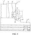
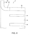
- the crimp retainer 5 is formed with a ring-shaped portion 51 which is formed with a ring-shaped flange portion 52 and a ring-shaped sleeve portion 53, whose cross section is formed in the shape of an L and which is formed in the shape of a disc and a crimp part 54 which protrudes from the sleeve portion 53 in the axial direction and is deformed by crimping.
- the sleeve portion 53 and the crimp part 54 are formed to fit to the outer circumference of the rotor shaft 4, and the sleeve portion 53 is fitted to the rotor shaft 4 and thus is located in the radial direction with respect to the rotor shaft 4.
- the ring-shaped portion 51 of the crimp retainer 5 its cross section is formed in the shape of an L with the flange portion 52 and the sleeve portion 53 such that shape rigidity, that is, bending rigidity with respect to a flat surface perpendicular to the shaft is acquired by the sleeve portion 53 and circular rigidity is acquired by the flange portion 52.
- the crimp retainer 5 is fitted from the side of the crimp groove 43 to the rotor shaft 4, and is, as shown in FIG. 6 , brought into contact with the stepped portion between the small-diameter hole 21 and the large-diameter hole 22 of the end plate 2 on the one side of the flange portion 52. Then, a pressure is applied from the side of the crimp retainer 5 in the axial direction such that a constant pre-pressure (pre-load) is applied to the end plate 3, the core 1 and the end plate 2 arranged between the crimp retainer 5 and the protrusion portion 42 of the rotor shaft 4.
- pre-load a constant pre-pressure
- the crimp part 54 of the crimp retainer 5 is bent by crimp processing from the outer circumference into the crimp groove 43 inwardly in the radial direction, thus is fitted into the crimp groove 43 and is located with respect to the rotor shaft 4 in the axial direction. Then, in the crimp retainer 5, the bending end of the crimp part 54 is pressed onto the wall surface of the bottom portion of the crimp groove 43, is prevented from being moved outwardly in the axial direction and is strutted, and thus it is possible to locate and fix the crimp retainer 5 on the rotor shaft 4 with the pre-pressure kept applied to both the end plates 2 and 3 and the core 1.
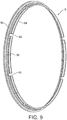
- the slits 55 described above having a small width may be arranged regularly, for example, at eight places in the circumferential direction, and as shown in FIG. 10 , the slits 55 having a large width may be arranged regularly, for example, at four places in the circumferential direction.
- FIGS. 9 and 10 show an example of the width and the number of slits 55, and as necessary, the width and the number thereof are preferably changed and set.
- the dimension of the core 1 in the stacked state in the axial direction is changed for each stacked core 1.
- An error in the stacking dimension described above causes the position of the crimp retainer 5 in the axial direction to be changed.
- the dimension of the crimp part 54 in the axial direction is set such that the crimp part 54 of the crimp retainer 5 straddles the crimp groove 43.
- the crimp part 54 is engaged with the wall surface on the outside of the crimp groove 43 in the axial direction, and the end of the crimp part 54 extends off the end portion of the crimp groove 43.
- the position of the crimp part 54 of the crimp retainer 5 facing the crimp groove 43 is moved outwardly in the axial direction, straddles the crimp groove 43 and is positioned further outwardly in the axial direction.
- the crimp part 54 is engaged with the wall surface on the outside of the crimp groove 43 in the axial direction and the end of the crimp part 54 extends off the end portion of the crimp groove 43 more than shown in FIG. 11(B) .
- the position of the crimp part 54 of the crimp retainer 5 facing the crimp groove 43 is moved inwardly in the axial direction, and the end of the crimp part 54 is arranged in an end of the region of the crimp groove 43.
- the end of the crimp part 54 does not extend off the end portion of the crimp groove 43 on the outside in the axial direction, and is, as shown in FIG. 11(A) , engaged with the wall surface on the outside of the crimp groove 43 in the axial direction.
- FIGS. 12 to 15 show a second embodiment of a rotor mechanism of a rotating electrical machine according to the present invention.
- FIG. 12 is a cross-sectional view of the rotor mechanism of the rotating electrical machine and
- FIG. 13 is a cross-sectional view of the crimp retainer.
- the ring-shaped portion of the crimp retainer is changed into a spring structure that makes the flange portion act in the axial direction, which is added to the first embodiment.
- the same devices as in the first embodiment are identified with the same symbols, and their description will be omitted or simplified.
- the crimp retainer 5 of the present embodiment is formed with the ring-shaped portion 51 composed of a tapered flange portion 56 and the ring-shaped sleeve portion 53 and the crimp part 54 that protrudes from the sleeve portion 53 in the axial direction and that is deformed by crimping.
- This crimp retainer 5 is formed of a high elastic material, for example, with high tensile strength steel sheets commonly referred to as a "high-tension material.”
- the other configurations are the same as in the first embodiment.
- a compression force is applied in the axial direction, and thus the tapered flange portion 56 can be elastically deformed in such a direction that the taper angle is increased.
- the taper angle of the flange portion 56 is increased according to the compression force, and a dimension C without the compression in the axial direction shown in FIG. 13 being applied can be finally changed to a dimension D obtained by raising the flange portion 56 in a vertical direction by elastic deformation, as shown in FIG. 14 .
- the sleeve portion 53 and the crimp part 54 are formed to fit to the outer circumference of the rotor shaft 4, and the sleeve portion 53 is fitted to the rotor shaft 4 to be located in the radial direction with respect to the rotor shaft 4.
- the crimp retainer 5 is fitted to the rotor shaft 4 from the side of the crimp groove 43, and, as shown in FIG. 12 , the end of the flange portion 56 is brought into contact with the side surface of the one end plate 2. Then, the sleeve portion 53 and the crimp part 54 of the crimp retainer 5 are pressed from the side of the crimp retainer 5 in the axial direction such that a constant pre-pressure (pre-load) is applied to the end plate 3, the core 1 and the end plate 2 arranged between the crimp retainer 5 and the protrusion portion 42 of the rotor shaft 4.
- the flange portion 56 of the crimp retainer 5 is elastically deformed by the constant pre-pressure (pre-load) described above such that the taper angle is increased.
- the crimp part 54 of the crimp retainer 5 is bent by crimp processing from the outer circumference into the crimp groove 43 inwardly in the radial direction, thus is fitted into the crimp groove 43 and is located with respect to the rotor shaft 4 in the axial direction. Then, in the crimp retainer 5, the bending end of the crimp part 54 is pressed onto the wall surface of the bottom portion of the crimp groove 43, is prevented from being moved outwardly in the axial direction and is strutted, and thus it is possible to locate and fix the crimp retainer 5 on the rotor shaft 4 with the pre-pressure kept applied to both the end plates 2 and 3 and the core 1.
- FIG. 15 shows a state where the position of the one end plate 2 is changed to the side of the crimp retainer 5 caused by an error in the stacking dimension described above.
- the amount of elastic deformation of the flange portion 56 of the crimp retainer 5 is changed by the error in the stacking dimension described above.
Landscapes
- Engineering & Computer Science (AREA)
- Power Engineering (AREA)
- Manufacturing & Machinery (AREA)
- Iron Core Of Rotating Electric Machines (AREA)
- Manufacture Of Motors, Generators (AREA)
Claims (7)
- Mécanisme de rotor d'une machine électrique tournante qui comporte un noyau (1) obtenu en empilant une pluralité de plaques d'acier magnétiques discoïdes sur une circonférence extérieure d'un arbre de rotor (4) et des plaques d'extrémité (2, 3) discoïdes agencées des deux côtés du noyau (1) dans une direction axiale,
dans lequel l'arbre de rotor (4) comporte une rainure de sertissage (43) qui est formée dans une partie circonférentielle extérieure de l'arbre de rotor (4) dans une direction circonférentielle, la rainure de sertissage étant située sur un extérieur dans la direction axiale par rapport à l'une quelconque des plaques d'extrémité (2, 3),
l'extérieur étant éloigné d'une région de support du noyau (1), et l'intérieur étant le côté opposé de l'extérieur,
la plaque d'extrémité (2) est située dans la direction axiale par une extrémité intérieure d'un élément de retenue de sertissage (5) dans la direction axiale qui est en forme d'anneau, qui recouvre la rainure de sertissage (43) de l'arbre de rotor (4) pour s'ajuster à l'arbre de rotor (4), qui est ajusté dans la rainure de sertissage (43) de l'arbre de rotor (4) en sertissant une partie extérieure de l'élément de retenue de sertissage (5) dans la direction axiale à partir d'un côté circonférentiel extérieur et qui est en prise avec une surface de paroi de la rainure de sertissage (43) sur l'extérieur dans la direction axiale, et
caractérisé en ce que
l'élément de retenue de sertissage (5) comporte, dans la partie extérieure de l'élément de retenue de sertissage (5) dans la direction axiale, des fentes (55) qui s'étendent à partir d'une partie d'extrémité extérieure de l'élément de retenue de sertissage (5) dans la direction axiale vers un intérieur dans la direction axiale. - Mécanisme de rotor de la machine électrique tournante selon la revendication 1,
dans lequel l'élément de retenue de sertissage (5) comporte, dans la partie extérieure de l'élément de retenue de sertissage (5) dans la direction axiale serti à partir du côté circonférentiel extérieur pour s'ajuster dans la rainure de sertissage (43) de l'arbre de rotor (4), des fentes qui s'étendent à partir de la partie d'extrémité extérieure de l'élément de retenue de sertissage (5) dans la direction axiale vers l'intérieur dans la direction axiale en étant écartées d'un espace angulaire prédéterminé dans la direction circonférentielle. - Mécanisme de rotor de la machine électrique tournante selon la revendication 1 ou 2,
dans lequel l'élément de retenue de sertissage (5) est, selon une position de la plaque d'extrémité (2) dans la direction axiale en contact avec l'extrémité intérieure de l'élément de retenue de sertissage (5) dans la direction axiale, serti à partir du côté circonférentiel extérieur et ajusté dans la rainure de sertissage (43) de l'arbre de rotor (4), et la position dans la direction axiale en prise avec la surface de la paroi de la rainure de sertissage (43) sur l'extérieur dans la direction axiale est modifiée. - Mécanisme de rotor de la machine électrique tournante selon l'une quelconque des revendications 1 à 3,
dans lequel l'élément de retenue de sertissage (5) comporte, dans l'extrémité intérieure de l'élément de retenue de sertissage (5) dans la direction axiale, une partie de bride en forme d'anneau (52) s'étendant dans une direction radiale, et est mis en contact avec la plaque d'extrémité (2) au moyen de la partie de bride en forme d'anneau (52). - Mécanisme de rotor de la machine électrique tournante selon la revendication 1 ou 2,
dans lequel l'élément de retenue de sertissage (5) comporte, dans l'extrémité intérieure de l'élément de retenue de sertissage (5) dans la direction axiale, une partie de bride en forme d'anneau (52) s'étendant dans une direction radiale, la partie de bride (56) est formée de manière oblique pour être effilée de sorte qu'une extrémité de la partie de bride (56) soit mise en contact avec la plaque d'extrémité (2) et un angle d'inclinaison effilé soit modifié selon une position de la plaque d'extrémité (2) dans la direction axiale en contact avec l'extrémité intérieure de l'élément de retenue de sertissage (5) dans la direction axiale. - Mécanisme de rotor de la machine électrique tournante selon l'une quelconque des revendications 1 à 4,
dans lequel la rainure de sertissage (43) est formée autour d'une circonférence entière de la partie circonférentielle extérieure de l'arbre de rotor (4). - Procédé de fabrication d'un mécanisme de rotor d'une machine électrique tournante qui comporte un noyau (1) obtenu en empilant une pluralité de plaques d'acier magnétiques discoïdes sur une circonférence extérieure d'un arbre de rotor (4) et des plaques d'extrémité (2, 3) discoïdes agencées des deux côtés du noyau (1) dans une direction axiale,
dans lequel l'arbre de rotor (4) comporte une rainure de sertissage (43) qui est formée dans une partie circonférentielle extérieure de l'arbre de rotor (4) dans une direction circonférentielle, la rainure de sertissage étant située sur un extérieur dans la direction axiale par rapport à l'une quelconque des plaques d'extrémité (2, 3),
l'extérieur étant éloigné d'une région de support du noyau (1), et l'intérieur étant le côté opposé de l'extérieur,
caractérisé en ce que
un élément de retenue de sertissage (5) en forme d'anneau comportant, dans une partie extérieure de l'élément de retenue de sertissage (5) dans la direction axiale, des fentes (55) qui s'étendent à partir d'une partie d'extrémité extérieure de l'élément de retenue de sertissage (5) dans la direction axiale vers un intérieur dans la direction axiale est ajusté à l'arbre de rotor (4) pour recouvrir la rainure de sertissage (43) de l'arbre de rotor (4), et une extrémité intérieure de l'élément de retenue de sertissage (5) dans la direction axiale est pressée sur celui-ci en appliquant une pré-pression sur la plaque d'extrémité (2) et
la partie extérieure de l'élément de retenue de sertissage (5) dans la direction axiale est ensuite sertie à partir d'un côté circonférentiel extérieur pour s'ajuster dans la rainure de sertissage (43) de l'arbre de rotor (4) et est en prise avec une surface de paroi de la rainure de sertissage (43) sur l'extérieur dans la direction axiale de sorte que la plaque d'extrémité (2) soit située dans la direction axiale.
Applications Claiming Priority (3)
| Application Number | Priority Date | Filing Date | Title |
|---|---|---|---|
| JP2011045287 | 2011-03-02 | ||
| JP2012043774A JP5880136B2 (ja) | 2011-03-02 | 2012-02-29 | 回転電機のロータ構造およびその製造方法 |
| PCT/JP2012/055267 WO2012118157A1 (fr) | 2011-03-02 | 2012-03-01 | Structure de rotor de machine électrique tournante et son procédé de fabrication |
Publications (3)
| Publication Number | Publication Date |
|---|---|
| EP2683060A1 EP2683060A1 (fr) | 2014-01-08 |
| EP2683060A4 EP2683060A4 (fr) | 2016-05-11 |
| EP2683060B1 true EP2683060B1 (fr) | 2017-05-10 |
Family
ID=46758083
Family Applications (1)
| Application Number | Title | Priority Date | Filing Date |
|---|---|---|---|
| EP12752558.2A Not-in-force EP2683060B1 (fr) | 2011-03-02 | 2012-03-01 | Structure de rotor de machine électrique tournante et son procédé de fabrication |
Country Status (5)
| Country | Link |
|---|---|
| US (1) | US9318924B2 (fr) |
| EP (1) | EP2683060B1 (fr) |
| JP (1) | JP5880136B2 (fr) |
| CN (1) | CN103283122B (fr) |
| WO (1) | WO2012118157A1 (fr) |
Families Citing this family (10)
| Publication number | Priority date | Publication date | Assignee | Title |
|---|---|---|---|---|
| JP5796376B2 (ja) * | 2011-07-05 | 2015-10-21 | 日産自動車株式会社 | 電動モータのロータ |
| JP2015220950A (ja) * | 2014-05-21 | 2015-12-07 | 富士電機株式会社 | 回転電機 |
| JP2019009898A (ja) * | 2017-06-23 | 2019-01-17 | アイシン精機株式会社 | モータ |
| JP7053381B2 (ja) * | 2018-06-13 | 2022-04-12 | Ntn株式会社 | ロータユニット、電動モータ及び電動アクチュエータ |
| KR102649706B1 (ko) * | 2019-04-12 | 2024-03-19 | 엘지마그나 이파워트레인 주식회사 | 모터 |
| US11552517B2 (en) * | 2020-05-08 | 2023-01-10 | Schaeffler Technologies AG & Co. KG | Self-retaining compressional diaphragm spring |
| DE102020116612A1 (de) | 2020-06-24 | 2021-12-30 | Schaeffler Technologies AG & Co. KG | Rotor und Radialflussmaschine |
| DE102020210497A1 (de) | 2020-08-19 | 2022-02-24 | Zf Friedrichshafen Ag | Rotor einer permanenterregten elektrischen Maschine |
| DE102020132470A1 (de) | 2020-12-07 | 2022-06-09 | Schaeffler Technologies AG & Co. KG | Axiale Fixierung einer Wellenkomponente einer elektrischen Maschine |
| CN114915062B (zh) * | 2022-06-10 | 2025-03-07 | 珠海格力电器股份有限公司 | 转子组件及电机 |
Family Cites Families (18)
| Publication number | Priority date | Publication date | Assignee | Title |
|---|---|---|---|---|
| FR2707813B1 (fr) * | 1993-07-16 | 2000-12-29 | Mitsuba Electric Mfg C | Rotor de magnéto-générateur et procédé pour sa fabrication. |
| JPH07212912A (ja) | 1994-01-20 | 1995-08-11 | Fuji Electric Co Ltd | 電気自動車の電気制動制御方法 |
| JP2004048925A (ja) * | 2002-07-12 | 2004-02-12 | Toyota Motor Corp | ステータの固定方法及び固定構造並びにロータの固定方法及び固定構造 |
| KR100469463B1 (ko) * | 2002-09-10 | 2005-02-02 | 엘지전자 주식회사 | 왕복동식 압축기의 고정자 결합구조 |
| JP2004156716A (ja) * | 2002-11-07 | 2004-06-03 | Kayaba Ind Co Ltd | 軸部材に被固定部材を固定する固定方法および固定部の構造 |
| EP1599928B1 (fr) * | 2003-02-26 | 2013-08-28 | Robert Bosch Gmbh | Moteur electrique comportant un aimant permanent |
| EP1596487A1 (fr) * | 2004-05-10 | 2005-11-16 | Siemens Aktiengesellschaft | Rotor et méthode de production d'un rotor pour mécanisme de commande à moteur électrique pour véhicules automobiles |
| JP2006067668A (ja) | 2004-08-25 | 2006-03-09 | Nissan Motor Co Ltd | 電動機制御装置 |
| JP4586531B2 (ja) | 2004-12-27 | 2010-11-24 | 日産自動車株式会社 | ロータ構造 |
| JP4492521B2 (ja) * | 2005-10-26 | 2010-06-30 | トヨタ自動車株式会社 | ロータシャフトの製造方法 |
| US7358637B2 (en) * | 2005-11-04 | 2008-04-15 | Canopy Technologies, Llc | Method of compressing lamination stacks for permanent magnet rotor |
| JP2008109804A (ja) * | 2006-10-26 | 2008-05-08 | Toyota Motor Corp | 回転電機 |
| JP2008193772A (ja) | 2007-02-01 | 2008-08-21 | Toyota Motor Corp | 電気自動車の制御装置および制御方法、ならびに電気自動車 |
| JP4502039B2 (ja) * | 2008-04-15 | 2010-07-14 | トヨタ自動車株式会社 | 電動機回転子製造方法、及び、電動機回転子 |
| US7812495B2 (en) * | 2008-05-16 | 2010-10-12 | Honeywell International Inc. | Sleeve in end rings for permanent magnet rotor |
| JP2010148250A (ja) | 2008-12-19 | 2010-07-01 | Mitsubishi Motors Corp | 電気自動車の制御装置 |
| US8970085B2 (en) * | 2011-04-01 | 2015-03-03 | Denso Corporation | Rotor for electric rotating machine and method of manufacturing the same |
| US9130434B2 (en) * | 2012-02-01 | 2015-09-08 | Remy Technologies, Llc | Induction rotor end ring support device |
-
2012
- 2012-02-29 JP JP2012043774A patent/JP5880136B2/ja not_active Expired - Fee Related
- 2012-03-01 US US14/002,012 patent/US9318924B2/en not_active Expired - Fee Related
- 2012-03-01 EP EP12752558.2A patent/EP2683060B1/fr not_active Not-in-force
- 2012-03-01 WO PCT/JP2012/055267 patent/WO2012118157A1/fr not_active Ceased
- 2012-03-01 CN CN201280004439.0A patent/CN103283122B/zh not_active Expired - Fee Related
Also Published As
| Publication number | Publication date |
|---|---|
| US20130334926A1 (en) | 2013-12-19 |
| US9318924B2 (en) | 2016-04-19 |
| EP2683060A4 (fr) | 2016-05-11 |
| CN103283122B (zh) | 2016-02-17 |
| JP5880136B2 (ja) | 2016-03-08 |
| CN103283122A (zh) | 2013-09-04 |
| WO2012118157A1 (fr) | 2012-09-07 |
| JP2012196125A (ja) | 2012-10-11 |
| EP2683060A1 (fr) | 2014-01-08 |
Similar Documents
| Publication | Publication Date | Title |
|---|---|---|
| EP2683060B1 (fr) | Structure de rotor de machine électrique tournante et son procédé de fabrication | |
| US10411542B2 (en) | Fixing structure and fixing method for wire connection plate, and rotating electrical machine | |
| CN102593971B (zh) | 用于旋转电机的定子以及制造所述定子的方法 | |
| US10536043B2 (en) | Modular unit comprising a laminate stack for an electric machine, method for producing such a modular unit, and electric machine | |
| US20130193801A1 (en) | Conical spring washer for mounting a stator in the housing of an electrical machine | |
| JP6272821B2 (ja) | タブ形リベット接合部を有するクラッチアッセンブリ及び該クラッチアッセンブリに関する方法 | |
| US20090217493A1 (en) | Hoop retaining ring | |
| US9647518B2 (en) | Method for manufacturing laminated iron core | |
| US20210376696A1 (en) | Method of manufacturing coil and method of manufacturing motor | |
| JP6232641B2 (ja) | 固定子鉄心の製造方法 | |
| CN207766109U (zh) | 马达 | |
| JP2008193806A (ja) | モータ | |
| CN106662156A (zh) | 轴承装置和轴承装置的制造方法 | |
| CN106030154B (zh) | 滚珠丝杠装置 | |
| CN102948044A (zh) | 电机 | |
| US11218037B2 (en) | Stator and housing for rotating electrical machine | |
| EP2975278B1 (fr) | Palier à roulement et procédé de fabrication d'un tel palier | |
| JP7057295B2 (ja) | コイルの組付け方法 | |
| JP7820260B2 (ja) | スラスト軸受 | |
| EP2731234A1 (fr) | Rotor de moteur électrique | |
| JP2007143325A (ja) | 電気モータのステータ構造 | |
| JP5809993B2 (ja) | 回転電機 | |
| JP4947985B2 (ja) | 積層体の製造方法 | |
| JP5923290B2 (ja) | ロータコアの固定方法 | |
| KR20250115917A (ko) | 전동 모터의 로터와 그 제조 방법 |
Legal Events
| Date | Code | Title | Description |
|---|---|---|---|
| PUAI | Public reference made under article 153(3) epc to a published international application that has entered the european phase |
Free format text: ORIGINAL CODE: 0009012 |
|
| 17P | Request for examination filed |
Effective date: 20130719 |
|
| AK | Designated contracting states |
Kind code of ref document: A1 Designated state(s): AL AT BE BG CH CY CZ DE DK EE ES FI FR GB GR HR HU IE IS IT LI LT LU LV MC MK MT NL NO PL PT RO RS SE SI SK SM TR |
|
| DAX | Request for extension of the european patent (deleted) | ||
| RA4 | Supplementary search report drawn up and despatched (corrected) |
Effective date: 20160411 |
|
| RIC1 | Information provided on ipc code assigned before grant |
Ipc: H02K 1/28 20060101AFI20160405BHEP Ipc: H02K 15/02 20060101ALI20160405BHEP |
|
| GRAP | Despatch of communication of intention to grant a patent |
Free format text: ORIGINAL CODE: EPIDOSNIGR1 |
|
| INTG | Intention to grant announced |
Effective date: 20170104 |
|
| GRAS | Grant fee paid |
Free format text: ORIGINAL CODE: EPIDOSNIGR3 |
|
| GRAA | (expected) grant |
Free format text: ORIGINAL CODE: 0009210 |
|
| RIN1 | Information on inventor provided before grant (corrected) |
Inventor name: MIYAOKA, HIROSHI Inventor name: MORITA, TSUKASA Inventor name: TAGUCHI, NAOTO |
|
| AK | Designated contracting states |
Kind code of ref document: B1 Designated state(s): AL AT BE BG CH CY CZ DE DK EE ES FI FR GB GR HR HU IE IS IT LI LT LU LV MC MK MT NL NO PL PT RO RS SE SI SK SM TR |
|
| REG | Reference to a national code |
Ref country code: GB Ref legal event code: FG4D |
|
| REG | Reference to a national code |
Ref country code: AT Ref legal event code: REF Ref document number: 893271 Country of ref document: AT Kind code of ref document: T Effective date: 20170515 Ref country code: CH Ref legal event code: EP |
|
| REG | Reference to a national code |
Ref country code: IE Ref legal event code: FG4D |
|
| REG | Reference to a national code |
Ref country code: DE Ref legal event code: R096 Ref document number: 602012032268 Country of ref document: DE |
|
| REG | Reference to a national code |
Ref country code: NL Ref legal event code: MP Effective date: 20170510 |
|
| REG | Reference to a national code |
Ref country code: LT Ref legal event code: MG4D |
|
| REG | Reference to a national code |
Ref country code: AT Ref legal event code: MK05 Ref document number: 893271 Country of ref document: AT Kind code of ref document: T Effective date: 20170510 |
|
| PG25 | Lapsed in a contracting state [announced via postgrant information from national office to epo] |
Ref country code: GR Free format text: LAPSE BECAUSE OF FAILURE TO SUBMIT A TRANSLATION OF THE DESCRIPTION OR TO PAY THE FEE WITHIN THE PRESCRIBED TIME-LIMIT Effective date: 20170811 Ref country code: LT Free format text: LAPSE BECAUSE OF FAILURE TO SUBMIT A TRANSLATION OF THE DESCRIPTION OR TO PAY THE FEE WITHIN THE PRESCRIBED TIME-LIMIT Effective date: 20170510 Ref country code: HR Free format text: LAPSE BECAUSE OF FAILURE TO SUBMIT A TRANSLATION OF THE DESCRIPTION OR TO PAY THE FEE WITHIN THE PRESCRIBED TIME-LIMIT Effective date: 20170510 Ref country code: NO Free format text: LAPSE BECAUSE OF FAILURE TO SUBMIT A TRANSLATION OF THE DESCRIPTION OR TO PAY THE FEE WITHIN THE PRESCRIBED TIME-LIMIT Effective date: 20170810 Ref country code: ES Free format text: LAPSE BECAUSE OF FAILURE TO SUBMIT A TRANSLATION OF THE DESCRIPTION OR TO PAY THE FEE WITHIN THE PRESCRIBED TIME-LIMIT Effective date: 20170510 Ref country code: FI Free format text: LAPSE BECAUSE OF FAILURE TO SUBMIT A TRANSLATION OF THE DESCRIPTION OR TO PAY THE FEE WITHIN THE PRESCRIBED TIME-LIMIT Effective date: 20170510 Ref country code: AT Free format text: LAPSE BECAUSE OF FAILURE TO SUBMIT A TRANSLATION OF THE DESCRIPTION OR TO PAY THE FEE WITHIN THE PRESCRIBED TIME-LIMIT Effective date: 20170510 |
|
| PG25 | Lapsed in a contracting state [announced via postgrant information from national office to epo] |
Ref country code: IS Free format text: LAPSE BECAUSE OF FAILURE TO SUBMIT A TRANSLATION OF THE DESCRIPTION OR TO PAY THE FEE WITHIN THE PRESCRIBED TIME-LIMIT Effective date: 20170910 Ref country code: BG Free format text: LAPSE BECAUSE OF FAILURE TO SUBMIT A TRANSLATION OF THE DESCRIPTION OR TO PAY THE FEE WITHIN THE PRESCRIBED TIME-LIMIT Effective date: 20170810 Ref country code: NL Free format text: LAPSE BECAUSE OF FAILURE TO SUBMIT A TRANSLATION OF THE DESCRIPTION OR TO PAY THE FEE WITHIN THE PRESCRIBED TIME-LIMIT Effective date: 20170510 Ref country code: RS Free format text: LAPSE BECAUSE OF FAILURE TO SUBMIT A TRANSLATION OF THE DESCRIPTION OR TO PAY THE FEE WITHIN THE PRESCRIBED TIME-LIMIT Effective date: 20170510 Ref country code: SE Free format text: LAPSE BECAUSE OF FAILURE TO SUBMIT A TRANSLATION OF THE DESCRIPTION OR TO PAY THE FEE WITHIN THE PRESCRIBED TIME-LIMIT Effective date: 20170510 Ref country code: LV Free format text: LAPSE BECAUSE OF FAILURE TO SUBMIT A TRANSLATION OF THE DESCRIPTION OR TO PAY THE FEE WITHIN THE PRESCRIBED TIME-LIMIT Effective date: 20170510 Ref country code: PL Free format text: LAPSE BECAUSE OF FAILURE TO SUBMIT A TRANSLATION OF THE DESCRIPTION OR TO PAY THE FEE WITHIN THE PRESCRIBED TIME-LIMIT Effective date: 20170510 |
|
| REG | Reference to a national code |
Ref country code: FR Ref legal event code: PLFP Year of fee payment: 7 |
|
| PG25 | Lapsed in a contracting state [announced via postgrant information from national office to epo] |
Ref country code: SK Free format text: LAPSE BECAUSE OF FAILURE TO SUBMIT A TRANSLATION OF THE DESCRIPTION OR TO PAY THE FEE WITHIN THE PRESCRIBED TIME-LIMIT Effective date: 20170510 Ref country code: CZ Free format text: LAPSE BECAUSE OF FAILURE TO SUBMIT A TRANSLATION OF THE DESCRIPTION OR TO PAY THE FEE WITHIN THE PRESCRIBED TIME-LIMIT Effective date: 20170510 Ref country code: DK Free format text: LAPSE BECAUSE OF FAILURE TO SUBMIT A TRANSLATION OF THE DESCRIPTION OR TO PAY THE FEE WITHIN THE PRESCRIBED TIME-LIMIT Effective date: 20170510 Ref country code: EE Free format text: LAPSE BECAUSE OF FAILURE TO SUBMIT A TRANSLATION OF THE DESCRIPTION OR TO PAY THE FEE WITHIN THE PRESCRIBED TIME-LIMIT Effective date: 20170510 Ref country code: RO Free format text: LAPSE BECAUSE OF FAILURE TO SUBMIT A TRANSLATION OF THE DESCRIPTION OR TO PAY THE FEE WITHIN THE PRESCRIBED TIME-LIMIT Effective date: 20170510 |
|
| REG | Reference to a national code |
Ref country code: DE Ref legal event code: R097 Ref document number: 602012032268 Country of ref document: DE |
|
| PG25 | Lapsed in a contracting state [announced via postgrant information from national office to epo] |
Ref country code: SM Free format text: LAPSE BECAUSE OF FAILURE TO SUBMIT A TRANSLATION OF THE DESCRIPTION OR TO PAY THE FEE WITHIN THE PRESCRIBED TIME-LIMIT Effective date: 20170510 Ref country code: IT Free format text: LAPSE BECAUSE OF FAILURE TO SUBMIT A TRANSLATION OF THE DESCRIPTION OR TO PAY THE FEE WITHIN THE PRESCRIBED TIME-LIMIT Effective date: 20170510 |
|
| PLBE | No opposition filed within time limit |
Free format text: ORIGINAL CODE: 0009261 |
|
| STAA | Information on the status of an ep patent application or granted ep patent |
Free format text: STATUS: NO OPPOSITION FILED WITHIN TIME LIMIT |
|
| 26N | No opposition filed |
Effective date: 20180213 |
|
| PG25 | Lapsed in a contracting state [announced via postgrant information from national office to epo] |
Ref country code: SI Free format text: LAPSE BECAUSE OF FAILURE TO SUBMIT A TRANSLATION OF THE DESCRIPTION OR TO PAY THE FEE WITHIN THE PRESCRIBED TIME-LIMIT Effective date: 20170510 |
|
| REG | Reference to a national code |
Ref country code: CH Ref legal event code: PL |
|
| PG25 | Lapsed in a contracting state [announced via postgrant information from national office to epo] |
Ref country code: MC Free format text: LAPSE BECAUSE OF FAILURE TO SUBMIT A TRANSLATION OF THE DESCRIPTION OR TO PAY THE FEE WITHIN THE PRESCRIBED TIME-LIMIT Effective date: 20170510 |
|
| REG | Reference to a national code |
Ref country code: BE Ref legal event code: MM Effective date: 20180331 |
|
| REG | Reference to a national code |
Ref country code: IE Ref legal event code: MM4A |
|
| PG25 | Lapsed in a contracting state [announced via postgrant information from national office to epo] |
Ref country code: LU Free format text: LAPSE BECAUSE OF NON-PAYMENT OF DUE FEES Effective date: 20180301 |
|
| PG25 | Lapsed in a contracting state [announced via postgrant information from national office to epo] |
Ref country code: IE Free format text: LAPSE BECAUSE OF NON-PAYMENT OF DUE FEES Effective date: 20180301 |
|
| PG25 | Lapsed in a contracting state [announced via postgrant information from national office to epo] |
Ref country code: BE Free format text: LAPSE BECAUSE OF NON-PAYMENT OF DUE FEES Effective date: 20180331 Ref country code: CH Free format text: LAPSE BECAUSE OF NON-PAYMENT OF DUE FEES Effective date: 20180331 Ref country code: LI Free format text: LAPSE BECAUSE OF NON-PAYMENT OF DUE FEES Effective date: 20180331 |
|
| PG25 | Lapsed in a contracting state [announced via postgrant information from national office to epo] |
Ref country code: MT Free format text: LAPSE BECAUSE OF NON-PAYMENT OF DUE FEES Effective date: 20180301 |
|
| PG25 | Lapsed in a contracting state [announced via postgrant information from national office to epo] |
Ref country code: TR Free format text: LAPSE BECAUSE OF FAILURE TO SUBMIT A TRANSLATION OF THE DESCRIPTION OR TO PAY THE FEE WITHIN THE PRESCRIBED TIME-LIMIT Effective date: 20170510 |
|
| PG25 | Lapsed in a contracting state [announced via postgrant information from national office to epo] |
Ref country code: PT Free format text: LAPSE BECAUSE OF FAILURE TO SUBMIT A TRANSLATION OF THE DESCRIPTION OR TO PAY THE FEE WITHIN THE PRESCRIBED TIME-LIMIT Effective date: 20170510 Ref country code: HU Free format text: LAPSE BECAUSE OF FAILURE TO SUBMIT A TRANSLATION OF THE DESCRIPTION OR TO PAY THE FEE WITHIN THE PRESCRIBED TIME-LIMIT; INVALID AB INITIO Effective date: 20120301 |
|
| PG25 | Lapsed in a contracting state [announced via postgrant information from national office to epo] |
Ref country code: CY Free format text: LAPSE BECAUSE OF FAILURE TO SUBMIT A TRANSLATION OF THE DESCRIPTION OR TO PAY THE FEE WITHIN THE PRESCRIBED TIME-LIMIT Effective date: 20170510 Ref country code: MK Free format text: LAPSE BECAUSE OF NON-PAYMENT OF DUE FEES Effective date: 20170510 |
|
| PG25 | Lapsed in a contracting state [announced via postgrant information from national office to epo] |
Ref country code: AL Free format text: LAPSE BECAUSE OF FAILURE TO SUBMIT A TRANSLATION OF THE DESCRIPTION OR TO PAY THE FEE WITHIN THE PRESCRIBED TIME-LIMIT Effective date: 20170510 |
|
| PGFP | Annual fee paid to national office [announced via postgrant information from national office to epo] |
Ref country code: GB Payment date: 20220106 Year of fee payment: 11 Ref country code: DE Payment date: 20220105 Year of fee payment: 11 |
|
| PGFP | Annual fee paid to national office [announced via postgrant information from national office to epo] |
Ref country code: FR Payment date: 20220118 Year of fee payment: 11 |
|
| REG | Reference to a national code |
Ref country code: DE Ref legal event code: R119 Ref document number: 602012032268 Country of ref document: DE |
|
| GBPC | Gb: european patent ceased through non-payment of renewal fee |
Effective date: 20230301 |
|
| PG25 | Lapsed in a contracting state [announced via postgrant information from national office to epo] |
Ref country code: GB Free format text: LAPSE BECAUSE OF NON-PAYMENT OF DUE FEES Effective date: 20230301 |
|
| PG25 | Lapsed in a contracting state [announced via postgrant information from national office to epo] |
Ref country code: GB Free format text: LAPSE BECAUSE OF NON-PAYMENT OF DUE FEES Effective date: 20230301 Ref country code: FR Free format text: LAPSE BECAUSE OF NON-PAYMENT OF DUE FEES Effective date: 20230331 Ref country code: DE Free format text: LAPSE BECAUSE OF NON-PAYMENT OF DUE FEES Effective date: 20231003 |