EP2683077A1 - Dispositif de commande de la puissance synchrone d'un système de génération basé sur des convertisseurs statiques de puissance - Google Patents
Dispositif de commande de la puissance synchrone d'un système de génération basé sur des convertisseurs statiques de puissance Download PDFInfo
- Publication number
- EP2683077A1 EP2683077A1 EP12751872.8A EP12751872A EP2683077A1 EP 2683077 A1 EP2683077 A1 EP 2683077A1 EP 12751872 A EP12751872 A EP 12751872A EP 2683077 A1 EP2683077 A1 EP 2683077A1
- Authority
- EP
- European Patent Office
- Prior art keywords
- controller
- virtual
- power
- grid
- block
- Prior art date
- Legal status (The legal status is an assumption and is not a legal conclusion. Google has not performed a legal analysis and makes no representation as to the accuracy of the status listed.)
- Granted
Links
Images

Classifications
-
- H—ELECTRICITY
- H02—GENERATION; CONVERSION OR DISTRIBUTION OF ELECTRIC POWER
- H02P—CONTROL OR REGULATION OF ELECTRIC MOTORS, ELECTRIC GENERATORS OR DYNAMO-ELECTRIC CONVERTERS; CONTROLLING TRANSFORMERS, REACTORS OR CHOKE COILS
- H02P9/00—Arrangements for controlling electric generators for the purpose of obtaining a desired output
-
- H—ELECTRICITY
- H02—GENERATION; CONVERSION OR DISTRIBUTION OF ELECTRIC POWER
- H02M—APPARATUS FOR CONVERSION BETWEEN AC AND AC, BETWEEN AC AND DC, OR BETWEEN DC AND DC, AND FOR USE WITH MAINS OR SIMILAR POWER SUPPLY SYSTEMS; CONVERSION OF DC OR AC INPUT POWER INTO SURGE OUTPUT POWER; CONTROL OR REGULATION THEREOF
- H02M7/00—Conversion of AC power input into DC power output; Conversion of DC power input into AC power output
- H02M7/42—Conversion of DC power input into AC power output without possibility of reversal
- H02M7/44—Conversion of DC power input into AC power output without possibility of reversal by static converters
-
- H—ELECTRICITY
- H02—GENERATION; CONVERSION OR DISTRIBUTION OF ELECTRIC POWER
- H02J—ELECTRIC POWER NETWORKS; CIRCUIT ARRANGEMENTS OR SYSTEMS FOR SUPPLYING OR DISTRIBUTING ELECTRIC POWER; SYSTEMS FOR STORING ELECTRIC ENERGY
- H02J3/00—Circuit arrangements for AC mains or AC distribution networks
- H02J3/38—Arrangements for feeding a single network from two or more generators or sources in parallel; Arrangements for feeding already energised networks from additional generators or sources in parallel
- H02J3/381—Dispersed generators
-
- H—ELECTRICITY
- H02—GENERATION; CONVERSION OR DISTRIBUTION OF ELECTRIC POWER
- H02P—CONTROL OR REGULATION OF ELECTRIC MOTORS, ELECTRIC GENERATORS OR DYNAMO-ELECTRIC CONVERTERS; CONTROLLING TRANSFORMERS, REACTORS OR CHOKE COILS
- H02P9/00—Arrangements for controlling electric generators for the purpose of obtaining a desired output
- H02P9/10—Control effected upon generator excitation circuit to reduce harmful effects of overloads or transients, e.g. sudden application of load, sudden removal of load, sudden change of load
-
- H—ELECTRICITY
- H02—GENERATION; CONVERSION OR DISTRIBUTION OF ELECTRIC POWER
- H02P—CONTROL OR REGULATION OF ELECTRIC MOTORS, ELECTRIC GENERATORS OR DYNAMO-ELECTRIC CONVERTERS; CONTROLLING TRANSFORMERS, REACTORS OR CHOKE COILS
- H02P2101/00—Special adaptation of control arrangements for generators
- H02P2101/15—Special adaptation of control arrangements for generators for wind-driven turbines
Definitions
- the invention belongs to the technical sector of power controllers for renewable energy plants, especially useful in photovoltaic generation plants, which allows offering advanced functionalities to improve the connection of said plants to the electric grid.
- the sources of renewable energy mainly wind power plants (WIN) and photovoltaic (PH) power plants, have ceased to be a marginal resource in the generation of electricity.
- WIN wind power plants
- PH photovoltaic
- the generators of PH plants use power converters to connect to the electric grid. These power converters, also known as inverters, inject current to the voltage of the grid to supply power to the same.
- the PH inverters inject single-phase o tri-phase sinusoidal currents to the grid, depending on the power range of the generator. Normally, the currents injected to the grid tend to be sinusoidal and are in phase with the voltages of the coupling point to maximize the amount of active power being generated. There are no PH inverters in the market, at least in on a generalized basis, that inject currents to the quadrature with the grid voltages, which allows controlling the reactive power injected to the grid with the purpose of regulating the voltage level at the coupling point.
- TSO Transmission System Operator
- TSOs worldwide are increasingly becoming more demanding with respect to the features offered by renewable energy-based distributed generation plants. These requirements are materialized in the so-called grid codes. These types of codes are usually applied to generation technologies with a significant presence in the electric system. A clear example is the strict grid connection codes applied to wind generation systems, the PH systems being the next candidates to be regulated by these types of codes.
- TSOs intend for PH plants to increase their functionality and reliability with the purpose of avoiding having to pay third parties for auxiliary services that allow guaranteeing the stability of the electric system.
- the manufacturers and developers of PH systems are in charge of modernizing their technology to contribute the required systems, which will ultimately allow increasing the penetration of the PH energy systems in the electric grids in the following decade.
- the invention object of this patent supposes a solution to the problems represented by commercial inverters and conventional renewable power plants when they operate under generic conditions in the electric grid by offering the following:
- the Synchronous Power Controller of a generating system based on static power converters being claimed is a new concept in the control of latest generation renewable power plants that allows offering advanced functionalities to improve the integration of said plants to the electric grid.
- the controller of the invention comprises two main blocks referred to as: block 1 (electric block) (10) and block 2 (electromechanical block).
- Block 1 or the electric block, comprises a control loop at which input the existing voltage difference between a virtual internal electromotive force and the voltage existing at the point of the grid to which it is connected, is injected. This voltage difference supplies a virtual admittance, which determines the current to be injected to the grid by the inverter.
- the controller of the invention offers a different admittance for each frequency and each sequence, either direct, inverse, or homopolar. Therefore, the controller injects an elevated direct sequence current to the fundamental frequency of the grid, and to the other frequencies and sequences, including harmonics and transients, the controller injects the current that minimizes the potential existing perturbation.
- block 1 works with current references, instead of with voltage references (synchronous generators work with voltage references for the induced electromotive force, and, in consequence, the conventional controllers emulating the same also work with voltage references) and with a virtual admittance, instead of working with a virtual impedance (in synchronous generators, the ratio between the induced electromotive force and the circulating current is determined by an impedance, and therefore, the conventional controllers emulating the same also base their operation on the existence of a virtual impedance).
- Block 2 or the electromechanical block, unlike what is found in the state of the art, is not based on the imitation of the electromechanical characteristic of a synchronous generator, but it is configured as an adjustable power controller, which allows reaching an optimal response for the different power perturbations and fluctuations of the grid.
- this block 2 allows adjusting of the inertia and damping factor of the power control loop instantaneously, according to need at any time.
- This block 2 is formed by a control loop comprising a PLC (“power loop controller") that receives, at the input, the difference between the input power (power delivered to the converter by the primary source) and the power delivered to the grid, as well as inertia references and damping factors, among others.
- PLC power loop controller
- This block 2 or electromechanical characteristic controller, achieves flexibility for the set of the controller that allows, for example, reducing the inertia to facilitate the connection of the generator to the grid, or allocating higher inertias in the frequency ranges in which perturbations are desired to be eliminated.
- the frequency of the virtual internal electromotive force is obtained at the output of the PLC, which is integrated to obtain the phase of the virtual internal electromotive force vector that ultimately determines a set of virtual tri-phase voltages. These virtual voltages supply the electric block, which is the one ultimately calculating the current reference to be injected to the grid to exchange a certain power with the same.
- the references found that apply this concept are limited to the imitation of the electromechanical characteristic of the conventional synchronous generator, without introducing any type of improvement on said physical system.
- the synchronous power controller of the invention presents an evident difference with respect to the existing techniques, given that the inertia and the damping factor can be adjusted online and instantaneously according to the operating conditions.
- the synchronous power controller of the invention uses different values, both for the virtual inertia and the damping factor, for different frequency ranges, which supposes important progress with respect to other existing techniques.
- this type of controller contributes to the attenuation of power fluctuations, high-frequency harmonics, low-frequency fluctuations (grid modes), resonances, etc.
- the set of the synchronous power controller of a generating system based on static power converters presented by the invention is composed of two fundamental blocks or controllers: the virtual electrical characteristic controller and the virtual electromechanical characteristic controller.
- the electrical controller is supplied by the difference between the virtual internal electromotive force and the voltage at the connecting point of the grid and, by varying the parameters of the virtual admittance of the system according to the conditions of the grid at any given moment, the current to be delivered by the generation plant to the grid is determined.
- the electromechanical controller is supplied by the difference between the input power into the converter and the power delivered to the grid and, by varying the parameters corresponding to inertia and the damping factor of the system according to the conditions of the grid at any given moment, the frequency of the virtual internal electromotive force to be generated and to be used in the electrical controller is determined.
- the response of the controller of the invention presents a different dynamic behavior for the different frequency ranges of the grid.
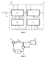
- Figure 1 shows the scheme representing the controller of the invention as a whole, formed by two main blocks: block 1 or the electric block (10), and block 2 or the electromechanical block (20).
- Block 2 (20) in turn comprises the virtual electrical characteristic controller (21), as well as the inertia and damping factor controller (22), to which a series of variables of the system are introduced, such as input voltage (v in ), input intensity (i in ), output voltage (v out ), and output intensity (i out ), which are used selectively depending on the specific algorithm of the controller being applied.
- the inertia and damping factor controller (22) also receives a series of input parameters, such as the powers of reference (P 1 , P 2 ..., P n ) and the adjustment constants of the response of the controller (c 1 , c 2 ..., c n ) for each frequency range.
- the inertia (J 1 , J 2 ... , J n ) and the damping factor values ( ⁇ 1 , ⁇ 2 , ... , ⁇ n ) are obtained for each frequency at the outlet.
- the virtual inertia and damping factor parameters are dynamically adapted to the operating conditions, offering a virtual inertia value (J 1 , J 2 ... , J n ) and damping factor value ( ⁇ 1 , ⁇ 2 , ..., ⁇ n ) for each frequency, such that establishing the capacity presented by the generator to attenuate different power, oscillations existing in the grid (inter-plant, inter-area... ) and in the primary generation source (mechanical and structural resonances), is possible.
- the input variable of the virtual electromechanical characteristic controller (21) is the power difference ( ⁇ P) between the input power (P in input power into the converter) and the power delivered to the grid (P out ).
- the virtual internal electromotive force (e), which is one of the input variables of block 1 or the electric block (10), is obtained from block 2 (20).
- This electric block (10) also comprises two parts: the virtual electrical characteristic controller (11) and the virtual admittance controller (12).
- the input variables of the virtual admittance controller (12) are voltage (v) and current (i) of the grid and the DC bus, which are used selectively depending on the specific algorithm of the controller being applied.
- the parameters of the virtual admittance controller (12) are the values of the current of reference for each frequency and sequence (I 1 *, I 2 *,..., I n *) and the adjustment constants of the response of the controller (c 1 , c 2 , ... , c n ) for each frequency range.
- this controller supplies the admittance value to be applied to each frequency and sequence (Y 1 , Y 2 ..., Y n ).
- the virtual electrical characteristic controller (11) receives the value of the virtual internal electromotive force (e), obtained from block 2 (20), and the voltage of the connecting point to the grid (v), as the input variables. Likewise, the virtual electrical characteristic controller (11) receives the virtual admittance values to be processed for each frequency and sequence of interest (Y 1 , Y 2 ..., Y n ), which were calculated in the virtual admittance controller (12), as the input parameters. Based on these input variables and parameters, block 1 (10) supplies the value of the current of reference (i*) that must be injected to the electric grid (15) by the power converter acting as a controlled current source (14) at the output.
- i* current of reference
- Figure 2 shows the control loop of block 1 (10) or electric block, at which input the voltage difference existing between a virtual internal electromotive force (e) and the voltage existing at the coupling point with the electric grid to which it is connected (v), is injected.
- This voltage difference supplies the virtual admittance processor (13), in charge of determining the current of reference (i*) to be injected to the grid (15) by the power converter.
- this virtual admittance (13) is dynamically adapted to the conditions of the grid. As shown in figure 3 , it also presents different behaviors for the different frequency ranges (f 1 , f 2 ..., f n ) and input sequences, either direct, inverse, or homopolar. This way, the controller of the invention offers a different admittance (Y 1 , Y 2 ... , Y n ) for each frequency (f 1 , f 2 ..., f n ). In this sense, the controller injects an elevated direct sequence current to the fundamental frequency of the grid, and to the other frequencies and sequences, including harmonics and transients, the controller injects the current that minimizes the potential existing perturbation.
- block 1 works with current references, instead of working with voltage references (conventional synchronous generators, as well as the controllers intended to emulate them, work with voltage references) and with a virtual admittance, instead of working with a virtual impedance (which is a characteristic parameter of conventional synchronous generators, and therefore, of the controllers intended to emulate them).
- FIG 4 shows the general scheme of block 2 (20) or electromechanical block.
- This block 2 comprises a control loop regulated by a PLC (23) ("power loop controller"), which receives the power difference ( ⁇ P) existing between the input power (P in ) (power delivered to the converter by the primary source) and the power delivered to the grid (P elec ), as well as a series of parameters establishing the natural frequency and the damping factor ( ⁇ ) desired at any given time for the power loop controller.
- the frequency of the virtual internal electromotive force ( ⁇ r ) which, once integrated, allows determining the phase ( ⁇ ) of the virtual internal voltages generated in the power converter, is obtained at the output of the PLC.
- this block 2 or electromechanical block achieves flexibility for the set of the synchronous power controller. This flexibility allows, for example, making a fast connection from the generator to the grid by decreasing the inertia and subsequently increasing the value thereof for certain frequency ranges in which there can be grid perturbations that should not be followed by the generator.
- the frequency of the virtual internal electromotive force is obtained at the output of the PLC, which is integrated to obtain the phase angle of the virtual internal electromotive force vector.
- a set of tri-phase voltages is obtained which constitute one of the input variables (e) of block 1 or electric block.
- the electric block After establishing the virtual internal voltage and its phase, the electric block will be in charge of transferring the grid powers by means of the injection of the corresponding current thereto.
- Figure 5 shows the operation of block 2 for the different frequency ranges (f 1 , f 2 , ...., f n ).
- the sum of the output references of the PLC (23) are applied to the VCO (24), which generates a set of frequency voltages w* and amplitude voltages E*. Subsequently, these voltages are applied to one of the inputs of the virtual electrical characteristic controller (11).
Landscapes
- Engineering & Computer Science (AREA)
- Power Engineering (AREA)
- Control Of Eletrric Generators (AREA)
- Supply And Distribution Of Alternating Current (AREA)
Priority Applications (1)
| Application Number | Priority Date | Filing Date | Title |
|---|---|---|---|
| EP22150672.8A EP4016832A1 (fr) | 2011-02-28 | 2012-02-27 | Contrôleur de puissance d'onduleur pour un système de génération basé sur un convertisseur de puissance statique |
Applications Claiming Priority (2)
| Application Number | Priority Date | Filing Date | Title |
|---|---|---|---|
| ES201100221A ES2402467B1 (es) | 2011-02-28 | 2011-02-28 | Controlador de potencia síncrona de un sistema de generación basado en convertidores estáticos de potencia. |
| PCT/ES2012/000046 WO2012117131A1 (fr) | 2011-02-28 | 2012-02-27 | Dispositif de commande de la puissance synchrone d'un système de génération basé sur des convertisseurs statiques de puissance |
Related Child Applications (2)
| Application Number | Title | Priority Date | Filing Date |
|---|---|---|---|
| EP22150672.8A Division EP4016832A1 (fr) | 2011-02-28 | 2012-02-27 | Contrôleur de puissance d'onduleur pour un système de génération basé sur un convertisseur de puissance statique |
| EP22150672.8A Division-Into EP4016832A1 (fr) | 2011-02-28 | 2012-02-27 | Contrôleur de puissance d'onduleur pour un système de génération basé sur un convertisseur de puissance statique |
Publications (3)
| Publication Number | Publication Date |
|---|---|
| EP2683077A1 true EP2683077A1 (fr) | 2014-01-08 |
| EP2683077A4 EP2683077A4 (fr) | 2017-10-04 |
| EP2683077B1 EP2683077B1 (fr) | 2022-04-06 |
Family
ID=46757382
Family Applications (2)
| Application Number | Title | Priority Date | Filing Date |
|---|---|---|---|
| EP22150672.8A Pending EP4016832A1 (fr) | 2011-02-28 | 2012-02-27 | Contrôleur de puissance d'onduleur pour un système de génération basé sur un convertisseur de puissance statique |
| EP12751872.8A Active EP2683077B1 (fr) | 2011-02-28 | 2012-02-27 | Dispositif de commande de la puissance synchrone d'un système de génération basé sur un convertisseur statique de puissance |
Family Applications Before (1)
| Application Number | Title | Priority Date | Filing Date |
|---|---|---|---|
| EP22150672.8A Pending EP4016832A1 (fr) | 2011-02-28 | 2012-02-27 | Contrôleur de puissance d'onduleur pour un système de génération basé sur un convertisseur de puissance statique |
Country Status (12)
| Country | Link |
|---|---|
| US (1) | US9166508B2 (fr) |
| EP (2) | EP4016832A1 (fr) |
| JP (1) | JP6277469B2 (fr) |
| CN (1) | CN103548250B (fr) |
| AU (1) | AU2012222318A1 (fr) |
| BR (1) | BR112013021813A2 (fr) |
| CL (1) | CL2013002452A1 (fr) |
| DK (1) | DK2683077T3 (fr) |
| ES (2) | ES2402467B1 (fr) |
| MX (1) | MX2013009778A (fr) |
| PT (1) | PT2683077T (fr) |
| WO (1) | WO2012117131A1 (fr) |
Cited By (4)
| Publication number | Priority date | Publication date | Assignee | Title |
|---|---|---|---|---|
| US9948103B2 (en) | 2012-11-15 | 2018-04-17 | Siemens Aktiengesellschaft | Method for the computer-aided control of the power in an electrical grid |
| US10873273B2 (en) | 2017-06-13 | 2020-12-22 | Hitachi, Ltd. | Renewable energy resources integrating power conversion apparatus |
| EP3836337A1 (fr) * | 2019-12-10 | 2021-06-16 | Wobben Properties GmbH | Procédure de limitation de courant d'une machine virtuelle synchrone, en particulier lors d'un défaut secteur |
| WO2021213655A1 (fr) * | 2020-04-23 | 2021-10-28 | Abb Power Grids Switzerland Ag | Agencement de prise en charge de puissance de réseau électrique fonctionnant en tant que machine synchrone virtuelle |
Families Citing this family (20)
| Publication number | Priority date | Publication date | Assignee | Title |
|---|---|---|---|---|
| ES2402499B1 (es) * | 2011-02-28 | 2013-11-26 | Abengoa Solar New Technologies S.A. | Controlador de la característica electromecánica virtual para convertidores estáticos de potencia. |
| ES2545674B1 (es) * | 2014-03-11 | 2016-06-29 | Gamesa Innovation & Technology, S.L. | Sistema de control de inercia para aerogenerador |
| CN104362914B (zh) * | 2014-09-28 | 2017-06-06 | 华北电力大学 | 一种励磁阻尼控制器与静止同步补偿器等价容量的实时计算方法 |
| WO2016134319A1 (fr) | 2015-02-19 | 2016-08-25 | Enphase Energy, Inc. | Procédé et appareil destinés à une commande de flexion en charge dans le domaine temporel comportant une commande de courant de phaseur intégrée |
| CN105515021B (zh) * | 2016-01-20 | 2017-12-19 | 清华大学 | 多模式附加次/超同步振荡控制方法和控制系统 |
| JP7052290B2 (ja) * | 2017-10-27 | 2022-04-12 | 東京電力ホールディングス株式会社 | 交直変換器制御装置 |
| CN109936150B (zh) * | 2017-12-15 | 2024-02-02 | 国家电网公司 | 一种虚拟惯量控制的优化控制方法、装置及其控制器 |
| GB2570151B (en) * | 2018-01-14 | 2020-07-15 | Zhong Qingchang | Reconfiguration of inertia, damping, and fault ride-through for a virtual synchronous machine |
| JP7013590B2 (ja) * | 2018-03-13 | 2022-01-31 | スーパーグリッド インスティテュート | 直流高電圧ラインを含む送電リンクの制御方法 |
| JP7025973B2 (ja) * | 2018-03-28 | 2022-02-25 | 株式会社日立製作所 | 分散電源の制御装置 |
| US10749446B2 (en) * | 2019-01-02 | 2020-08-18 | General Electric Company | Virtual synchronous generator system and method with virtual inertia control |
| FI3869682T3 (fi) * | 2020-02-24 | 2024-07-10 | Danfoss As | Menetelmä ja ohjauslaite tehonmuuntimen säätämiseksi |
| CN112886612B (zh) * | 2021-01-26 | 2022-10-04 | 中国电力科学研究院有限公司 | 确定双馈风机并网系统次超同步振荡控制器的方法和系统 |
| WO2023131414A1 (fr) | 2022-01-07 | 2023-07-13 | Huawei Digital Power Technologies Co., Ltd. | Appareil, système et procédé de conversion de puissance active destinés à être utilisés dans un appareil de conversion de puissance active |
| CN114498598A (zh) * | 2022-02-23 | 2022-05-13 | 兰州理工大学 | 一种基于扩展移相的dab虚拟惯性控制方法及应用 |
| CN114928101B (zh) * | 2022-05-05 | 2024-04-19 | 国网江苏省电力有限公司镇江供电分公司 | 一种光储虚拟电厂同步支撑有功功率控制方法 |
| CN114825441B (zh) * | 2022-05-10 | 2026-03-13 | 南京工程学院 | 并联逆变器并网系统自适应虚拟阻抗谐振抑制的控制方法 |
| CN115347604A (zh) * | 2022-07-26 | 2022-11-15 | 浙江工业大学 | 一种多虚拟直流电机并联系统的功率协调控制方法 |
| CN118249415A (zh) * | 2024-03-25 | 2024-06-25 | 国网江苏省电力有限公司镇江供电分公司 | 一种基于限幅Sigmoid函数的光伏并网系统虚拟惯量构网控制方法及系统 |
| CN121529830B (zh) * | 2025-11-25 | 2026-04-24 | 河北登望电力工程有限公司 | 一种虚拟电厂参与调频辅助服务的实时调度系统 |
Citations (1)
| Publication number | Priority date | Publication date | Assignee | Title |
|---|---|---|---|---|
| WO2010055322A2 (fr) | 2008-11-12 | 2010-05-20 | Ulive Enterprises Limited | Générateurs synchrones statiques |
Family Cites Families (15)
| Publication number | Priority date | Publication date | Assignee | Title |
|---|---|---|---|---|
| JP3652427B2 (ja) * | 1995-12-07 | 2005-05-25 | シャープ株式会社 | インバータ装置 |
| CH697550B1 (de) * | 2005-03-30 | 2008-11-28 | Alstom Technology Ltd | Verfahren zur Steuerung eines Frequenzkonverters. |
| US7456695B2 (en) * | 2006-01-10 | 2008-11-25 | General Electric Company | Apparatus, method and computer program product for tracking information in an electric grid |
| DE102006047792A1 (de) * | 2006-10-06 | 2008-04-10 | Technische Universität Clausthal | Konditionierungseinrichtung für Energieversorgungsnetze |
| CN101617234B (zh) * | 2006-11-06 | 2012-05-23 | 歌美飒创新技术公司 | 先进实时电网监控系统 |
| US7786919B2 (en) * | 2007-09-21 | 2010-08-31 | Siemens Industry, Inc. | Systems and/or devices for providing an isolated analog output or analog input |
| JP4859852B2 (ja) * | 2008-01-23 | 2012-01-25 | 三菱電機株式会社 | 系統安定化方法及び系統安定化装置 |
| KR101191695B1 (ko) * | 2008-08-26 | 2012-10-16 | 에이비비 테크놀로지 아게 | 동기 머신 에뮬레이션을 이용한 전압원 컨버터의 제어 |
| EP2359151B1 (fr) * | 2008-11-07 | 2015-08-19 | Vestas Wind Systems A/S | Système de surveillance de réseau électrique et procédé associé |
| KR101129625B1 (ko) * | 2009-12-02 | 2012-03-28 | 삼성중공업 주식회사 | 전력 제어 방법 및 장치 |
| CN101777776A (zh) * | 2010-04-07 | 2010-07-14 | 湖南亿能电子科技有限公司 | 一种基于同步发电机模型的智能型光伏并网逆变器控制方法 |
| WO2012062323A2 (fr) * | 2010-11-10 | 2012-05-18 | Vestas Wind Systems A/S | Procédé et système pour l'actionnement d'une éolienne |
| ES2402499B1 (es) * | 2011-02-28 | 2013-11-26 | Abengoa Solar New Technologies S.A. | Controlador de la característica electromecánica virtual para convertidores estáticos de potencia. |
| ES2402465B1 (es) * | 2011-02-28 | 2014-01-27 | Abengoa Solar New Technologies S.A. | Controlador de admitancia virtual basado en convertidores estáticos de potencia. |
| EP2660941A1 (fr) * | 2012-05-04 | 2013-11-06 | Siemens Aktiengesellschaft | Commande de générateur synchrone, système générateur et système d'énergie de navire |
-
2011
- 2011-02-28 ES ES201100221A patent/ES2402467B1/es active Active
-
2012
- 2012-02-27 EP EP22150672.8A patent/EP4016832A1/fr active Pending
- 2012-02-27 US US14/001,839 patent/US9166508B2/en active Active
- 2012-02-27 JP JP2013555909A patent/JP6277469B2/ja active Active
- 2012-02-27 AU AU2012222318A patent/AU2012222318A1/en not_active Abandoned
- 2012-02-27 CN CN201280020692.5A patent/CN103548250B/zh active Active
- 2012-02-27 ES ES12751872T patent/ES2918984T3/es active Active
- 2012-02-27 WO PCT/ES2012/000046 patent/WO2012117131A1/fr not_active Ceased
- 2012-02-27 BR BR112013021813A patent/BR112013021813A2/pt not_active IP Right Cessation
- 2012-02-27 MX MX2013009778A patent/MX2013009778A/es active IP Right Grant
- 2012-02-27 DK DK12751872.8T patent/DK2683077T3/da active
- 2012-02-27 PT PT127518728T patent/PT2683077T/pt unknown
- 2012-02-27 EP EP12751872.8A patent/EP2683077B1/fr active Active
-
2013
- 2013-08-26 CL CL2013002452A patent/CL2013002452A1/es unknown
Patent Citations (1)
| Publication number | Priority date | Publication date | Assignee | Title |
|---|---|---|---|---|
| WO2010055322A2 (fr) | 2008-11-12 | 2010-05-20 | Ulive Enterprises Limited | Générateurs synchrones statiques |
Non-Patent Citations (2)
| Title |
|---|
| "Control Strategy for Flexible Microgrid Based on Parallel Line-Interactive UPS Systems", IEEE TRANSACTIONS ON INDUSTRIAL ELECTRONICS, vol. 56, no. 3, 1 March 2009 (2009-03-01), GUERRERO J.M. ET AL, pages 726 - 736, XP011249055 |
| See also references of WO2012117131A1 |
Cited By (9)
| Publication number | Priority date | Publication date | Assignee | Title |
|---|---|---|---|---|
| US9948103B2 (en) | 2012-11-15 | 2018-04-17 | Siemens Aktiengesellschaft | Method for the computer-aided control of the power in an electrical grid |
| EP2898581B1 (fr) * | 2012-11-15 | 2018-06-13 | Siemens Aktiengesellschaft | Procédé de commande de puissance assistée par ordinateur dans un réseau électrique |
| US10873273B2 (en) | 2017-06-13 | 2020-12-22 | Hitachi, Ltd. | Renewable energy resources integrating power conversion apparatus |
| EP3836337A1 (fr) * | 2019-12-10 | 2021-06-16 | Wobben Properties GmbH | Procédure de limitation de courant d'une machine virtuelle synchrone, en particulier lors d'un défaut secteur |
| WO2021213655A1 (fr) * | 2020-04-23 | 2021-10-28 | Abb Power Grids Switzerland Ag | Agencement de prise en charge de puissance de réseau électrique fonctionnant en tant que machine synchrone virtuelle |
| CN115461952A (zh) * | 2020-04-23 | 2022-12-09 | 日立能源瑞士股份公司 | 作为虚拟同步机运行的用于电力电网的电力支持装置 |
| EP4107836B1 (fr) | 2020-04-23 | 2023-07-19 | Hitachi Energy Switzerland AG | Agencement de prise en charge de puissance de réseau électrique fonctionnant en tant que machine synchrone virtuelle |
| CN115461952B (zh) * | 2020-04-23 | 2023-09-15 | 日立能源瑞士股份公司 | 作为虚拟同步机运行的用于电力电网的电力支持装置 |
| US11855454B2 (en) | 2020-04-23 | 2023-12-26 | Hitachi Energy Switzerland Ag | Power supporting arrangement for a power grid operated as a virtual synchronous machine |
Also Published As
| Publication number | Publication date |
|---|---|
| EP4016832A1 (fr) | 2022-06-22 |
| MX2013009778A (es) | 2014-03-27 |
| AU2012222318A1 (en) | 2013-10-24 |
| ES2402467A1 (es) | 2013-05-03 |
| BR112013021813A2 (pt) | 2016-10-25 |
| JP6277469B2 (ja) | 2018-02-14 |
| EP2683077B1 (fr) | 2022-04-06 |
| JP2014509179A (ja) | 2014-04-10 |
| DK2683077T3 (da) | 2022-05-23 |
| PT2683077T (pt) | 2022-04-20 |
| EP2683077A4 (fr) | 2017-10-04 |
| US20140049228A1 (en) | 2014-02-20 |
| US9166508B2 (en) | 2015-10-20 |
| ES2402467B1 (es) | 2014-01-27 |
| CL2013002452A1 (es) | 2014-08-18 |
| CN103548250A (zh) | 2014-01-29 |
| WO2012117131A1 (fr) | 2012-09-07 |
| ES2918984T3 (es) | 2022-07-21 |
| CN103548250B (zh) | 2016-08-24 |
Similar Documents
| Publication | Publication Date | Title |
|---|---|---|
| US9166508B2 (en) | Synchronous power controller for a generating system based on static power converters | |
| Shi et al. | Self-tuning virtual synchronous generator control for improving frequency stability in autonomous photovoltaic-diesel microgrids | |
| EP2683075A1 (fr) | Contrôleur de la caractéristique électromécanique virtuelle pour convertisseurs statiques de puissance | |
| Rodriguez et al. | Control of grid-connected power converters based on a virtual admittance control loop | |
| Ashabani et al. | General interface for power management of micro-grids using nonlinear cooperative droop control | |
| Bouzid et al. | Simulation of droop control strategy for parallel inverters in autonomous AC microgrids | |
| Liu et al. | An enhanced dual droop control scheme for resilient active power sharing among paralleled two-stage converters | |
| Nian et al. | Stability analysis and impedance reshaping method for DC resonance in VSCs-based power system | |
| US20140049233A1 (en) | Virtual admittance controller based on static power converters | |
| Yan et al. | Sequence impedance modeling of grid-forming inverters | |
| Luo et al. | Adaptive-output-voltage-regulation-based solution for the DC-link undervoltage of grid-forming inverters | |
| Meng et al. | A self-adaptive controller for inverter with seamless transfer and automatic pre-synchronization capability | |
| Alanazi et al. | Designing a new controller in the operation of the hybrid PV-BESS system to improve the transient stability | |
| Bin et al. | New control scheme of power decoupling based on virtual synchronous generator | |
| Alwaz et al. | Harmonic power sharing and power quality improvement of droop controller based low voltage islanded microgrid | |
| Karthik et al. | Hyperbolic Secant LMS Algorithm to Enhance Performance of a Three-Phase Single-Stage Grid Connected PV System | |
| Ferreira et al. | Single-phase synchronverter for residential PV power systems | |
| Ji et al. | Enhancement of low-voltage ride-through capability for virtual synchronous generators based on virtual impedance voltage control | |
| Yang et al. | Fast power control for VSCs to enhance the synchronization stability in ultra-weak grids | |
| Zheng et al. | Control strategy for suppressing power oscillation of virtual synchronous generator under unbalanced grid voltage | |
| Marin et al. | Stability analysis of a grid-connected VSC controlled by SPC | |
| Zhang et al. | Perturbation influences of parameters on dynamic performance of a virtual synchronous generator | |
| Ge et al. | Study on control strategy of circulation suppression in parallel with multiple VSG | |
| Alcala et al. | A three-phase back-to-back converter for reactive power compensation, current harmonic filtering and active power compensation | |
| Shahid et al. | Distributed co-control of interface inverters for harmonic-loss mitigation and power-sharing accuracy in micro-grids |
Legal Events
| Date | Code | Title | Description |
|---|---|---|---|
| TPAC | Observations filed by third parties |
Free format text: ORIGINAL CODE: EPIDOSNTIPA |
|
| PUAI | Public reference made under article 153(3) epc to a published international application that has entered the european phase |
Free format text: ORIGINAL CODE: 0009012 |
|
| 17P | Request for examination filed |
Effective date: 20130926 |
|
| AK | Designated contracting states |
Kind code of ref document: A1 Designated state(s): AL AT BE BG CH CY CZ DE DK EE ES FI FR GB GR HR HU IE IS IT LI LT LU LV MC MK MT NL NO PL PT RO RS SE SI SK SM TR |
|
| DAX | Request for extension of the european patent (deleted) | ||
| RA4 | Supplementary search report drawn up and despatched (corrected) |
Effective date: 20170906 |
|
| RIC1 | Information provided on ipc code assigned before grant |
Ipc: H02P 9/02 20060101AFI20170831BHEP Ipc: H02P 23/14 20060101ALI20170831BHEP Ipc: H02J 3/38 20060101ALI20170831BHEP Ipc: H02M 7/48 20070101ALI20170831BHEP Ipc: G05F 1/66 20060101ALI20170831BHEP Ipc: H02P 9/10 20060101ALI20170831BHEP Ipc: H02M 7/44 20060101ALI20170831BHEP |
|
| STAA | Information on the status of an ep patent application or granted ep patent |
Free format text: STATUS: EXAMINATION IS IN PROGRESS |
|
| 17Q | First examination report despatched |
Effective date: 20200818 |
|
| REG | Reference to a national code |
Ref country code: DE Ref legal event code: R079 Ref document number: 602012077981 Country of ref document: DE Free format text: PREVIOUS MAIN CLASS: H02P0009020000 Ipc: H02P0009100000 |
|
| RIC1 | Information provided on ipc code assigned before grant |
Ipc: H02J 3/38 20060101ALI20211004BHEP Ipc: H02M 7/44 20060101ALI20211004BHEP Ipc: H02P 9/10 20060101AFI20211004BHEP |
|
| GRAP | Despatch of communication of intention to grant a patent |
Free format text: ORIGINAL CODE: EPIDOSNIGR1 |
|
| STAA | Information on the status of an ep patent application or granted ep patent |
Free format text: STATUS: GRANT OF PATENT IS INTENDED |
|
| INTG | Intention to grant announced |
Effective date: 20211118 |
|
| RAP1 | Party data changed (applicant data changed or rights of an application transferred) |
Owner name: WOBBEN PROPERTIES GMBH |
|
| GRAS | Grant fee paid |
Free format text: ORIGINAL CODE: EPIDOSNIGR3 |
|
| GRAA | (expected) grant |
Free format text: ORIGINAL CODE: 0009210 |
|
| STAA | Information on the status of an ep patent application or granted ep patent |
Free format text: STATUS: THE PATENT HAS BEEN GRANTED |
|
| AK | Designated contracting states |
Kind code of ref document: B1 Designated state(s): AL AT BE BG CH CY CZ DE DK EE ES FI FR GB GR HR HU IE IS IT LI LT LU LV MC MK MT NL NO PL PT RO RS SE SI SK SM TR |
|
| REG | Reference to a national code |
Ref country code: GB Ref legal event code: FG4D |
|
| REG | Reference to a national code |
Ref country code: CH Ref legal event code: EP |
|
| REG | Reference to a national code |
Ref country code: AT Ref legal event code: REF Ref document number: 1482328 Country of ref document: AT Kind code of ref document: T Effective date: 20220415 |
|
| REG | Reference to a national code |
Ref country code: PT Ref legal event code: SC4A Ref document number: 2683077 Country of ref document: PT Date of ref document: 20220420 Kind code of ref document: T Free format text: AVAILABILITY OF NATIONAL TRANSLATION Effective date: 20220412 |
|
| REG | Reference to a national code |
Ref country code: DE Ref legal event code: R096 Ref document number: 602012077981 Country of ref document: DE |
|
| REG | Reference to a national code |
Ref country code: IE Ref legal event code: FG4D |
|
| REG | Reference to a national code |
Ref country code: NL Ref legal event code: FP |
|
| REG | Reference to a national code |
Ref country code: DK Ref legal event code: T3 Effective date: 20220517 |
|
| REG | Reference to a national code |
Ref country code: SE Ref legal event code: TRGR |
|
| REG | Reference to a national code |
Ref country code: ES Ref legal event code: FG2A Ref document number: 2918984 Country of ref document: ES Kind code of ref document: T3 Effective date: 20220721 |
|
| REG | Reference to a national code |
Ref country code: LT Ref legal event code: MG9D |
|
| REG | Reference to a national code |
Ref country code: AT Ref legal event code: MK05 Ref document number: 1482328 Country of ref document: AT Kind code of ref document: T Effective date: 20220406 |
|
| PG25 | Lapsed in a contracting state [announced via postgrant information from national office to epo] |
Ref country code: NO Free format text: LAPSE BECAUSE OF FAILURE TO SUBMIT A TRANSLATION OF THE DESCRIPTION OR TO PAY THE FEE WITHIN THE PRESCRIBED TIME-LIMIT Effective date: 20220706 Ref country code: LT Free format text: LAPSE BECAUSE OF FAILURE TO SUBMIT A TRANSLATION OF THE DESCRIPTION OR TO PAY THE FEE WITHIN THE PRESCRIBED TIME-LIMIT Effective date: 20220406 Ref country code: HR Free format text: LAPSE BECAUSE OF FAILURE TO SUBMIT A TRANSLATION OF THE DESCRIPTION OR TO PAY THE FEE WITHIN THE PRESCRIBED TIME-LIMIT Effective date: 20220406 Ref country code: GR Free format text: LAPSE BECAUSE OF FAILURE TO SUBMIT A TRANSLATION OF THE DESCRIPTION OR TO PAY THE FEE WITHIN THE PRESCRIBED TIME-LIMIT Effective date: 20220707 Ref country code: FI Free format text: LAPSE BECAUSE OF FAILURE TO SUBMIT A TRANSLATION OF THE DESCRIPTION OR TO PAY THE FEE WITHIN THE PRESCRIBED TIME-LIMIT Effective date: 20220406 Ref country code: BG Free format text: LAPSE BECAUSE OF FAILURE TO SUBMIT A TRANSLATION OF THE DESCRIPTION OR TO PAY THE FEE WITHIN THE PRESCRIBED TIME-LIMIT Effective date: 20220706 Ref country code: AT Free format text: LAPSE BECAUSE OF FAILURE TO SUBMIT A TRANSLATION OF THE DESCRIPTION OR TO PAY THE FEE WITHIN THE PRESCRIBED TIME-LIMIT Effective date: 20220406 |
|
| PG25 | Lapsed in a contracting state [announced via postgrant information from national office to epo] |
Ref country code: RS Free format text: LAPSE BECAUSE OF FAILURE TO SUBMIT A TRANSLATION OF THE DESCRIPTION OR TO PAY THE FEE WITHIN THE PRESCRIBED TIME-LIMIT Effective date: 20220406 Ref country code: PL Free format text: LAPSE BECAUSE OF FAILURE TO SUBMIT A TRANSLATION OF THE DESCRIPTION OR TO PAY THE FEE WITHIN THE PRESCRIBED TIME-LIMIT Effective date: 20220406 Ref country code: LV Free format text: LAPSE BECAUSE OF FAILURE TO SUBMIT A TRANSLATION OF THE DESCRIPTION OR TO PAY THE FEE WITHIN THE PRESCRIBED TIME-LIMIT Effective date: 20220406 Ref country code: IS Free format text: LAPSE BECAUSE OF FAILURE TO SUBMIT A TRANSLATION OF THE DESCRIPTION OR TO PAY THE FEE WITHIN THE PRESCRIBED TIME-LIMIT Effective date: 20220806 |
|
| REG | Reference to a national code |
Ref country code: DE Ref legal event code: R097 Ref document number: 602012077981 Country of ref document: DE |
|
| PG25 | Lapsed in a contracting state [announced via postgrant information from national office to epo] |
Ref country code: SM Free format text: LAPSE BECAUSE OF FAILURE TO SUBMIT A TRANSLATION OF THE DESCRIPTION OR TO PAY THE FEE WITHIN THE PRESCRIBED TIME-LIMIT Effective date: 20220406 Ref country code: SK Free format text: LAPSE BECAUSE OF FAILURE TO SUBMIT A TRANSLATION OF THE DESCRIPTION OR TO PAY THE FEE WITHIN THE PRESCRIBED TIME-LIMIT Effective date: 20220406 Ref country code: RO Free format text: LAPSE BECAUSE OF FAILURE TO SUBMIT A TRANSLATION OF THE DESCRIPTION OR TO PAY THE FEE WITHIN THE PRESCRIBED TIME-LIMIT Effective date: 20220406 Ref country code: EE Free format text: LAPSE BECAUSE OF FAILURE TO SUBMIT A TRANSLATION OF THE DESCRIPTION OR TO PAY THE FEE WITHIN THE PRESCRIBED TIME-LIMIT Effective date: 20220406 Ref country code: CZ Free format text: LAPSE BECAUSE OF FAILURE TO SUBMIT A TRANSLATION OF THE DESCRIPTION OR TO PAY THE FEE WITHIN THE PRESCRIBED TIME-LIMIT Effective date: 20220406 |
|
| PLBE | No opposition filed within time limit |
Free format text: ORIGINAL CODE: 0009261 |
|
| STAA | Information on the status of an ep patent application or granted ep patent |
Free format text: STATUS: NO OPPOSITION FILED WITHIN TIME LIMIT |
|
| 26N | No opposition filed |
Effective date: 20230110 |
|
| PG25 | Lapsed in a contracting state [announced via postgrant information from national office to epo] |
Ref country code: AL Free format text: LAPSE BECAUSE OF FAILURE TO SUBMIT A TRANSLATION OF THE DESCRIPTION OR TO PAY THE FEE WITHIN THE PRESCRIBED TIME-LIMIT Effective date: 20220406 |
|
| PG25 | Lapsed in a contracting state [announced via postgrant information from national office to epo] |
Ref country code: SI Free format text: LAPSE BECAUSE OF FAILURE TO SUBMIT A TRANSLATION OF THE DESCRIPTION OR TO PAY THE FEE WITHIN THE PRESCRIBED TIME-LIMIT Effective date: 20220406 |
|
| PG25 | Lapsed in a contracting state [announced via postgrant information from national office to epo] |
Ref country code: MC Free format text: LAPSE BECAUSE OF FAILURE TO SUBMIT A TRANSLATION OF THE DESCRIPTION OR TO PAY THE FEE WITHIN THE PRESCRIBED TIME-LIMIT Effective date: 20220406 |
|
| REG | Reference to a national code |
Ref country code: CH Ref legal event code: PL |
|
| REG | Reference to a national code |
Ref country code: BE Ref legal event code: MM Effective date: 20230228 |
|
| PG25 | Lapsed in a contracting state [announced via postgrant information from national office to epo] |
Ref country code: LU Free format text: LAPSE BECAUSE OF NON-PAYMENT OF DUE FEES Effective date: 20230227 Ref country code: LI Free format text: LAPSE BECAUSE OF NON-PAYMENT OF DUE FEES Effective date: 20230228 Ref country code: CH Free format text: LAPSE BECAUSE OF NON-PAYMENT OF DUE FEES Effective date: 20230228 |
|
| PG25 | Lapsed in a contracting state [announced via postgrant information from national office to epo] |
Ref country code: BE Free format text: LAPSE BECAUSE OF NON-PAYMENT OF DUE FEES Effective date: 20230228 |
|
| PG25 | Lapsed in a contracting state [announced via postgrant information from national office to epo] |
Ref country code: BG Free format text: LAPSE BECAUSE OF FAILURE TO SUBMIT A TRANSLATION OF THE DESCRIPTION OR TO PAY THE FEE WITHIN THE PRESCRIBED TIME-LIMIT Effective date: 20220406 |
|
| PG25 | Lapsed in a contracting state [announced via postgrant information from national office to epo] |
Ref country code: BG Free format text: LAPSE BECAUSE OF FAILURE TO SUBMIT A TRANSLATION OF THE DESCRIPTION OR TO PAY THE FEE WITHIN THE PRESCRIBED TIME-LIMIT Effective date: 20220406 |
|
| PGFP | Annual fee paid to national office [announced via postgrant information from national office to epo] |
Ref country code: NL Payment date: 20250220 Year of fee payment: 14 |
|
| PGFP | Annual fee paid to national office [announced via postgrant information from national office to epo] |
Ref country code: TR Payment date: 20250218 Year of fee payment: 14 |
|
| PG25 | Lapsed in a contracting state [announced via postgrant information from national office to epo] |
Ref country code: CY Free format text: LAPSE BECAUSE OF FAILURE TO SUBMIT A TRANSLATION OF THE DESCRIPTION OR TO PAY THE FEE WITHIN THE PRESCRIBED TIME-LIMIT; INVALID AB INITIO Effective date: 20120227 |
|
| PG25 | Lapsed in a contracting state [announced via postgrant information from national office to epo] |
Ref country code: HU Free format text: LAPSE BECAUSE OF FAILURE TO SUBMIT A TRANSLATION OF THE DESCRIPTION OR TO PAY THE FEE WITHIN THE PRESCRIBED TIME-LIMIT; INVALID AB INITIO Effective date: 20120227 |
|
| PGFP | Annual fee paid to national office [announced via postgrant information from national office to epo] |
Ref country code: SE Payment date: 20260218 Year of fee payment: 15 |
|
| PGFP | Annual fee paid to national office [announced via postgrant information from national office to epo] |
Ref country code: GB Payment date: 20260219 Year of fee payment: 15 |
|
| PGFP | Annual fee paid to national office [announced via postgrant information from national office to epo] |
Ref country code: ES Payment date: 20260319 Year of fee payment: 15 |
|
| PGFP | Annual fee paid to national office [announced via postgrant information from national office to epo] |
Ref country code: DK Payment date: 20260217 Year of fee payment: 15 Ref country code: IE Payment date: 20260218 Year of fee payment: 15 Ref country code: DE Payment date: 20260302 Year of fee payment: 15 |
|
| PGFP | Annual fee paid to national office [announced via postgrant information from national office to epo] |
Ref country code: IT Payment date: 20260227 Year of fee payment: 15 |
|
| PGFP | Annual fee paid to national office [announced via postgrant information from national office to epo] |
Ref country code: FR Payment date: 20260219 Year of fee payment: 15 |
|
| PGFP | Annual fee paid to national office [announced via postgrant information from national office to epo] |
Ref country code: PT Payment date: 20260213 Year of fee payment: 15 |