EP2684099B1 - Verfahren und vorrichtung zur überwachung eines servoventilbetätigungssystems - Google Patents
Verfahren und vorrichtung zur überwachung eines servoventilbetätigungssystems Download PDFInfo
- Publication number
- EP2684099B1 EP2684099B1 EP12711934.5A EP12711934A EP2684099B1 EP 2684099 B1 EP2684099 B1 EP 2684099B1 EP 12711934 A EP12711934 A EP 12711934A EP 2684099 B1 EP2684099 B1 EP 2684099B1
- Authority
- EP
- European Patent Office
- Prior art keywords
- servovalve
- control device
- monitoring method
- average value
- pos
- Prior art date
- Legal status (The legal status is an assumption and is not a legal conclusion. Google has not performed a legal analysis and makes no representation as to the accuracy of the status listed.)
- Active
Links
Images
Classifications
-
- G—PHYSICS
- G01—MEASURING; TESTING
- G01M—TESTING STATIC OR DYNAMIC BALANCE OF MACHINES OR STRUCTURES; TESTING OF STRUCTURES OR APPARATUS, NOT OTHERWISE PROVIDED FOR
- G01M15/00—Testing of engines
- G01M15/14—Testing gas-turbine engines or jet-propulsion engines
-
- F—MECHANICAL ENGINEERING; LIGHTING; HEATING; WEAPONS; BLASTING
- F02—COMBUSTION ENGINES; HOT-GAS OR COMBUSTION-PRODUCT ENGINE PLANTS
- F02C—GAS-TURBINE PLANTS; AIR INTAKES FOR JET-PROPULSION PLANTS; CONTROLLING FUEL SUPPLY IN AIR-BREATHING JET-PROPULSION PLANTS
- F02C9/00—Controlling gas-turbine plants; Controlling fuel supply in air- breathing jet-propulsion plants
- F02C9/26—Control of fuel supply
-
- G—PHYSICS
- G05—CONTROLLING; REGULATING
- G05B—CONTROL OR REGULATING SYSTEMS IN GENERAL; FUNCTIONAL ELEMENTS OF SUCH SYSTEMS; MONITORING OR TESTING ARRANGEMENTS FOR SUCH SYSTEMS OR ELEMENTS
- G05B23/00—Testing or monitoring of control systems or parts thereof
- G05B23/02—Electric testing or monitoring
- G05B23/0205—Electric testing or monitoring by means of a monitoring system capable of detecting and responding to faults
- G05B23/0218—Electric testing or monitoring by means of a monitoring system capable of detecting and responding to faults characterised by the fault detection method dealing with either existing or incipient faults
- G05B23/0224—Process history based detection method, e.g. whereby history implies the availability of large amounts of data
- G05B23/0227—Qualitative history assessment, whereby the type of data acted upon, e.g. waveforms, images or patterns, is not relevant, e.g. rule based assessment; if-then decisions
- G05B23/0235—Qualitative history assessment, whereby the type of data acted upon, e.g. waveforms, images or patterns, is not relevant, e.g. rule based assessment; if-then decisions based on a comparison with predetermined threshold or range, e.g. "classical methods", carried out during normal operation; threshold adaptation or choice; when or how to compare with the threshold
-
- F—MECHANICAL ENGINEERING; LIGHTING; HEATING; WEAPONS; BLASTING
- F15—FLUID-PRESSURE ACTUATORS; HYDRAULICS OR PNEUMATICS IN GENERAL
- F15B—SYSTEMS ACTING BY MEANS OF FLUIDS IN GENERAL; FLUID-PRESSURE ACTUATORS, e.g. SERVOMOTORS; DETAILS OF FLUID-PRESSURE SYSTEMS, NOT OTHERWISE PROVIDED FOR
- F15B21/00—Common features of fluid actuator systems; Fluid-pressure actuator systems or details thereof, not covered by any other group of this subclass
- F15B21/08—Servomotor systems incorporating electrically operated control means
- F15B21/087—Control strategy, e.g. with block diagram
-
- F—MECHANICAL ENGINEERING; LIGHTING; HEATING; WEAPONS; BLASTING
- F15—FLUID-PRESSURE ACTUATORS; HYDRAULICS OR PNEUMATICS IN GENERAL
- F15B—SYSTEMS ACTING BY MEANS OF FLUIDS IN GENERAL; FLUID-PRESSURE ACTUATORS, e.g. SERVOMOTORS; DETAILS OF FLUID-PRESSURE SYSTEMS, NOT OTHERWISE PROVIDED FOR
- F15B9/00—Servomotors with follow-up action, e.g. obtained by feed-back control, i.e. in which the position of the actuated member conforms with that of the controlling member
- F15B9/02—Servomotors with follow-up action, e.g. obtained by feed-back control, i.e. in which the position of the actuated member conforms with that of the controlling member with servomotors of the reciprocatable or oscillatable type
- F15B9/08—Servomotors with follow-up action, e.g. obtained by feed-back control, i.e. in which the position of the actuated member conforms with that of the controlling member with servomotors of the reciprocatable or oscillatable type controlled by valves affecting the fluid feed or the fluid outlet of the servomotor
- F15B9/09—Servomotors with follow-up action, e.g. obtained by feed-back control, i.e. in which the position of the actuated member conforms with that of the controlling member with servomotors of the reciprocatable or oscillatable type controlled by valves affecting the fluid feed or the fluid outlet of the servomotor with electrical control means
-
- G—PHYSICS
- G05—CONTROLLING; REGULATING
- G05B—CONTROL OR REGULATING SYSTEMS IN GENERAL; FUNCTIONAL ELEMENTS OF SUCH SYSTEMS; MONITORING OR TESTING ARRANGEMENTS FOR SUCH SYSTEMS OR ELEMENTS
- G05B23/00—Testing or monitoring of control systems or parts thereof
- G05B23/02—Electric testing or monitoring
- G05B23/0205—Electric testing or monitoring by means of a monitoring system capable of detecting and responding to faults
- G05B23/0259—Electric testing or monitoring by means of a monitoring system capable of detecting and responding to faults characterized by the response to fault detection
- G05B23/0283—Predictive maintenance, e.g. involving the monitoring of a system and, based on the monitoring results, taking decisions on the maintenance schedule of the monitored system; Estimating remaining useful life [RUL]
-
- F—MECHANICAL ENGINEERING; LIGHTING; HEATING; WEAPONS; BLASTING
- F15—FLUID-PRESSURE ACTUATORS; HYDRAULICS OR PNEUMATICS IN GENERAL
- F15B—SYSTEMS ACTING BY MEANS OF FLUIDS IN GENERAL; FLUID-PRESSURE ACTUATORS, e.g. SERVOMOTORS; DETAILS OF FLUID-PRESSURE SYSTEMS, NOT OTHERWISE PROVIDED FOR
- F15B19/00—Testing; Calibrating; Fault detection or monitoring; Simulation or modelling of fluid-pressure systems or apparatus not otherwise provided for
- F15B19/005—Fault detection or monitoring
-
- F—MECHANICAL ENGINEERING; LIGHTING; HEATING; WEAPONS; BLASTING
- F16—ENGINEERING ELEMENTS AND UNITS; GENERAL MEASURES FOR PRODUCING AND MAINTAINING EFFECTIVE FUNCTIONING OF MACHINES OR INSTALLATIONS; THERMAL INSULATION IN GENERAL
- F16K—VALVES; TAPS; COCKS; ACTUATING-FLOATS; DEVICES FOR VENTING OR AERATING
- F16K37/00—Special means in or on valves or other cut-off apparatus for indicating or recording operation thereof, or for enabling an alarm to be given
- F16K37/0025—Electrical or magnetic means
- F16K37/0041—Electrical or magnetic means for measuring valve parameters
-
- F—MECHANICAL ENGINEERING; LIGHTING; HEATING; WEAPONS; BLASTING
- F16—ENGINEERING ELEMENTS AND UNITS; GENERAL MEASURES FOR PRODUCING AND MAINTAINING EFFECTIVE FUNCTIONING OF MACHINES OR INSTALLATIONS; THERMAL INSULATION IN GENERAL
- F16K—VALVES; TAPS; COCKS; ACTUATING-FLOATS; DEVICES FOR VENTING OR AERATING
- F16K37/00—Special means in or on valves or other cut-off apparatus for indicating or recording operation thereof, or for enabling an alarm to be given
- F16K37/0075—For recording or indicating the functioning of a valve in combination with test equipment
- F16K37/0083—For recording or indicating the functioning of a valve in combination with test equipment by measuring valve parameters
-
- G—PHYSICS
- G05—CONTROLLING; REGULATING
- G05B—CONTROL OR REGULATING SYSTEMS IN GENERAL; FUNCTIONAL ELEMENTS OF SUCH SYSTEMS; MONITORING OR TESTING ARRANGEMENTS FOR SUCH SYSTEMS OR ELEMENTS
- G05B2219/00—Program-control systems
- G05B2219/30—Nc systems
- G05B2219/42—Servomotor, servo controller kind till VSS
- G05B2219/42271—Monitor parameters, conditions servo for maintenance, lubrication, repair purposes
Definitions
- the present invention relates to the general field of servovalve actuating systems.
- the invention relates in particular to an actuation system for an aircraft turbojet engine.
- a turbojet engine typically comprises servovalve actuation systems for controlling variable geometries of the turbojet engine.
- variable geometries of the turbojet engine is meant here engine or its environment whose dimensions, shapes, positions and / or speeds are likely to be modified, according to detected events or engine operating parameters.
- examples of “variable geometries” are statically variable stator vanes of compressor rectifiers, compressor discharge valves, turbine blade tips, and a fuel metering device.
- these actuation systems are controlled by the electronic control module of the engine control system or EEC (for " Electronic Engine Control "), so as to adapt the variable geometry to the flight scenario. Control is ensured by means of servo loops.
- EEC Electronic Engine Control
- variable geometry actuation systems in a turbojet engine is crucial in terms of availability and efficiency of the turbojet engine.
- Degradations of these actuating systems are reflected in particular by positions and / or dimensions of turbojet components that do not comply with the controls of the ECU in steady state, or by a slow response of these devices to these transient controls. These degradations are first steps of failure because they are generally, at first, either compensated by the servo control loops of the actuating systems or without any notable consequence other than a reconfiguration (for example, a change of control channel active).
- a particular type of degradation is the drift of the quiescent current of the servovalve, as shown in FIG. figure 2 .
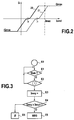
- the figure 2 is a graph that represents an operating curve of a servovalve. More precisely, the graph of the figure 2 illustrates the evolution of the hydraulic flow Q delivered by the servovalve 3 to a cylinder, as a function of the control current I cmd .
- I max represents the maximum value of the control current I cmd that the ECU is capable of supplying.
- Curve 20 corresponds to a nominal state of the servovalve and shows that the quiescent current of the servovalve, that is to say the control current required to maintain the cylinder in a given position, has a non-zero value I 0 . In the nominal state, the current I max, however, provides the maximum hydraulic flow Q max .
- Curve 21 represents a non-nominal state of the servovalve, for example a state after aging. It is found that the quiescent current has a value I 1 greater than I 0 . In other words, there was drift of the quiescent current of the servovalve. Moreover, in the non-nominal state of the curve 21, the current I max no longer makes it possible to provide the maximum hydraulic flow Q max . In other words, the curve 21 corresponds to a degraded state of the servovalve.
- the document US2009 / 0306830 discloses a method of monitoring a valve system in which a switching time of a valve element is measured between two positions. If this time exceeds a predetermined threshold, the method determines whether this excess is due to system wear or general conditions.
- the general conditions are for example represented by the control current of a solenoid valve.
- the control current is compared with a reference value.
- this document does not describe that the control current taken into account is an average value of the control current during the detection of a stabilized state, the stabilized state being detected by verifying that the measured position of a jack remains constant.
- the described monitoring method requires switching of the valve member between two positions.
- the position of the cylinder corresponds to the position setpoint.
- the control current of the servovalve therefore corresponds to the quiescent current of the servovalve.
- the calculation of an average value of this current makes it possible to overcome the rapid variations and the comparison with a threshold makes it possible to test whether the drift of the quiescent current is acceptable or not.
- the monitoring method may comprise, before the determination step, a step of waiting for a waiting period during which the stabilized state is detected.
- the stabilized state is detected as a function of the position of the cylinder.
- the actuation system is a system for actuating variable geometries of an aircraft engine turbojet engine, the stabilized state being detected when the aircraft is on the ground.
- the average value can be determined according to the control current determined by the control device.
- the average value is therefore accurate because it is not influenced by the measurement accuracy of the control current.
- control device may comprise a proportional-integral regulator, the average value being determined as a function of the integral current of the regulator.
- the monitoring method comprises, when the average value is greater than or equal to the predetermined threshold, a step of generating a maintenance message.
- the various steps of the monitoring method are determined by computer program instructions.
- the invention also relates to a computer program on an information carrier, this program being capable of being implemented in a monitoring device or more generally in a computer, this program comprising instructions adapted to the implementation of the steps of a monitoring method as described above.
- This program can use any programming language, and be in the form of source code, object code, or intermediate code between source code and object code, such as in a partially compiled form, or in any other form desirable shape.
- the invention also relates to a computer-readable information medium, comprising instructions of a computer program as mentioned above.
- the information carrier may be any entity or device capable of storing the program.
- the medium may comprise storage means, such as a ROM, for example a CD ROM or a microelectronic circuit ROM, or a magnetic recording medium, for example a diskette (floppy disc) or a disk hard.
- the information medium may be a transmissible medium such as an electrical or optical signal, which may be conveyed via an electrical or optical cable, by radio or by other means.
- the program according to the invention can be downloaded in particular on an Internet type network.
- the information carrier may be an integrated circuit in which the program is incorporated, the circuit being adapted to execute or to be used in the execution of the method in question.
- the invention relates to the monitoring of servovalve actuation system servo control chains.
- the monitoring of a servo control chain of an actuating system controlling a variable geometry of a turbojet engine equipping an aircraft is envisaged.
- this hypothesis is in no way limiting.
- the invention also applies to other servovalve actuation systems, in particular to construction machinery, industrial robots, etc.
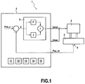
- the figure 1 represents an actuating system 1 controlling the position of a fuel metering device of a turbojet engine.
- the actuation system comprises a control device 2, a servovalve 3 and a cylinder 4.
- the position of the cylinder 4 influences the fuel flow delivered by the fuel dispenser (not shown).
- the control device 2 may be the ECU ( Engine Control Unit ), also known as the Full Authority Digital Engine Control (FADEC).
- ECU Engine Control Unit
- FADEC Full Authority Digital Engine Control
- the jack 4 is associated with a position sensor 5.
- the position of the jack 4 is controlled by the servovalve 3, itself controlled by the control device 2.
- the servo valve 3 adjusts the hydraulic power delivered to the actuator 4 based on an electric current command I cmd it receives from the control device 2.
- the position of the cylinder 4 measured by the sensor 5 is denoted Pos_m and is supplied to the control device 2.
- the control device 2 determines the difference ⁇ between the position Pos_m and a position command, denoted Pos_c.
- the difference ⁇ is supplied to a regulator 6, for example of the proportional-integral type, which determines the control current I cmd .
- the control device 2 here has the hardware architecture of a computer. It comprises in particular a processor 11, a non-volatile memory 12, a volatile memory 13, an interface 14 and a communication module 15.
- the processor 11 makes it possible to execute computer programs stored in the non-volatile memory 12, using the volatile memory 13.
- the interface 14 makes it possible on the one hand to acquire measurement signals, in particular the position Pos_m and a measurement of the control current I cmd , denoted by I mes , and on the other hand to transmit control signals, in particular the control current I cmd .
- the communication module 15 makes it possible to exchange data with other entities, in particular maintenance equipment.
- the determination of the position setpoint Pos_c and the difference ⁇ as well as the implementation of the regulator 6 correspond to a control program stored in the non-volatile memory 12 and executed by the processor 11.
- the quiescent current of the servovalve 3 is likely to derive. It will be understood that between the values I 0 and I 1 of the quiescent current, respectively corresponding to a nominal state and a degraded state, there is a current threshold I threshold up to which the drift of the quiescent current remains acceptable.
- a monitoring method according to the invention intended to determine whether the drift of the quiescent current of the servovalve 3 is acceptable or not.
- the monitoring method is implemented by the control device 2, which therefore also constitutes the monitoring device according to the invention.
- the process of monitoring the figure 3 starts at step E0 and then, at step E1, it is checked whether a stabilized state is detected.
- a stabilized state can be detected for example when the measured position Pos_m remains constant.
- step E1 When a stabilized state is not detected, the monitoring method loops in step E1. On the other hand, if a stabilized state is detected, the monitoring method continues in step E2.
- step E2 a predetermined waiting time is expected during which the stabilized state is detected.
- Step E2 is for example a counting loop of a number of real-time clock cycles. If at each counted cycle the steady state is detected, step E3 is taken when the cycle counter reaches a predetermined value. On the other hand, if the stabilized state is no longer detected before the cycle counter has reached the predetermined value, the monitoring method returns to step E1.
- Step E2 makes it possible to wait for the attenuation of possible transient effects due to the operation of the turbojet engine before the detection of the stabilized state in step E1.
- step E3 the average value I moy of the control current I cmd is determined for a predetermined duration during which the stabilized state is detected.
- the average value I moy represents the quiescent current of the servovalve 3. Indeed, when the stabilized state is detected, the measured position Pos_m is constant and equal to the setpoint Pos_c. The control current I cmd therefore serves simply to maintain the constant position.
- Step E3 is for example implemented by a counting loop of a number of real-time clock cycles.
- the sum S (n) is divided by n to obtain I moy :
- I Avg S not / not
- step E4 the monitoring method is reset (step E0).
- step E4 the monitoring method is reset (step E4).
- step E4 the current I av is compared with the current threshold I threshold .
- the maintenance message is for example stored in the non-volatile memory 12, then communicated to a maintenance equipment later, by the communication module 15.
- the waiting time of step E2 the time taken into account for calculating the average I moy and the value of the threshold I threshold can be chosen by the designer of the monitoring method, depending on the intended application.
- waiting time of step E2 and the time taken into account to calculate the average I moy in step E3 can each be 10 seconds.
- the total duration of the steps E2 and E3 during which it is necessary to detect a stabilized state is 20 seconds. Such a duration is less than the length of time an aircraft is idling on the ground before takeoff during a typical mission. It is therefore possible to detect a stabilized state and to perform the steps E2 and E3 at this time.
- an engine loop typically has a natural frequency corresponding to a period of about 4 seconds.
- the waiting time of 10 seconds is greater than the period of the motor loop and thus allows to wait for the attenuation of the transient effects.
- the value of the threshold can be chosen according to the nominal characteristic curve of the servovalve 3, the maximum current that the control device 2 is capable of supplying, and the accuracy of the current supplied by the control device 2.
- the average I moy is calculated as a function of the control current I cmd . More precisely, the average I moy is calculated as a function of the value of the control current I cmd calculated by the regulator 6. In the case of a proportional-integral regulator, this value is equal to the integral current of the regulator when the state stabilized is detected. Thus, the average I moy can be calculated as a function of the value of the integral current of the regulator. Alternatively, the mean I av can be calculated as a function of the measured value I mes of the control current I cmd . In this case, however, the average I av is influenced by the accuracy of the measurement.
- the steps of the figure 3 correspond to a monitoring program stored in the non-volatile memory 12 and executed by the processor 11.
- the identification of the quiescent current of the servovalve can make it possible to no longer saturate the integral part of the regulator 6 of proportional-integral type and thus to limit the error of dragging (during transients) on the cylinder position controlled by the servovalve.
- this increased accuracy provides more margin and therefore more robustness.
Landscapes
- Engineering & Computer Science (AREA)
- Physics & Mathematics (AREA)
- General Physics & Mathematics (AREA)
- Chemical & Material Sciences (AREA)
- General Engineering & Computer Science (AREA)
- Mechanical Engineering (AREA)
- Fluid Mechanics (AREA)
- Automation & Control Theory (AREA)
- Combustion & Propulsion (AREA)
- Analytical Chemistry (AREA)
- Control Of Turbines (AREA)
- Output Control And Ontrol Of Special Type Engine (AREA)
- Feedback Control In General (AREA)
Claims (9)
- Verfahren zur Überwachung eines Betätigungssystems (1), das eine Steuervorrichtung (2), ein Servoventil (3) und einen Zylinder (4), welcher durch das Servoventil (3) betätigt wird, umfasst, wobei die Steuervorrichtung geeignet ist, einen Steuerstrom (Icmd) in Abhängigkeit eines Positionssollwertes (Pos_c) und einer gemessenen Position (Pos_m) des Zylinders (4) zu bestimmen und den Steuerstrom (Icmd) an das Servoventil (3) zu liefern, wobei das Überwachungsverfahren dadurch gekennzeichnet ist, dass es umfasst:- einen Schritt (E1) zur Erfassung eines stabilisierten Zustands, indem überprüft wird, ob die gemessene Position (Pos_m) konstant bleibt,- einen Schritt (E3) zur Bestimmung eines Mittelwertes (Imoy) des Steuerstroms während der Erfassung des stabilisierten Zustands und- einen Schritt (E4) zum Vergleichen des Mittelwertes mit einem vorbestimmten Schwellwert.
- Überwachungsverfahren nach Anspruch 1, das vor dem Bestimmungsschritt (E3) einen Schritt (E2) zum Abwarten einer Wartezeit, während der der stabilisierte Zustand erfasst wird, umfasst.
- Überwachungsverfahren nach einem der Ansprüche 1 bis 2, bei dem das Betätigungssystem (1) ein System zur Betätigung von veränderlichen Geometrien einer Strahlturbine eines Luftfahrzeugtriebwerks ist, wobei der stabilisierte Zustand erfasst wird, wenn das Luftfahrzeug am Boden ist.
- Überwachungsverfahren nach einem der Ansprüche 1 bis 3, bei dem der Mittelwert (Imoy) in Abhängigkeit von dem durch die Steuervorrichtung bestimmten Steuerstrom bestimmt wird.
- Überwachungsverfahren nach Anspruch 4, bei dem die Steuervorrichtung (2) einen Proportional-Integral-Regler (6) umfasst, wobei der Mittelwert (Imoy) in Abhängigkeit von dem Integralstrom des Reglers (6) bestimmt wird.
- Überwachungsverfahren nach einem der Ansprüche 1 bis 5, das dann, wenn der Mittelwert größer als der oder gleich dem vorbestimmte(n) Schwellwert ist, einen Schritt (E5) zum Generieren einer Wartungsmeldung umfasst.
- Computerprogramm, umfassend Befehle für die Durchführung der Schritte eines Überwachungsverfahrens nach einem der Ansprüche 1 bis 6, wenn das Programm durch einen Computer ausgeführt wird.
- Durch einen Computer lesbarer Speicherträger, auf dem ein Computerprogramm, das Befehle für die Durchführung der Schritte eines Überwachungsverfahrens nach einem der Ansprüche 1 bis 6 umfasst, gespeichert ist.
- Steuervorrichtung (2) für ein Betätigungssystem (1), das die Steuervorrichtung (2), ein Servoventil (3) und einen Zylinder (4), welcher durch das Servoventil (3) betätigt wird, umfasst, wobei die Steuervorrichtung geeignet ist, einen Steuerstrom (Icmd) in Abhängigkeit eines Positionssollwertes (Pos_c) und einer gemessenen Position (Pos_m) des Zylinders (4) zu bestimmen und den Steuerstrom (Icmd) an das Servoventil (3) zu liefern, wobei die Steuervorrichtung dadurch gekennzeichnet ist, dass sie umfasst:- Mittel zur Erfassung eines stabilisierten Zustands, die geeignet sind, einen stabilisierten Zustand dadurch zu erfassen, dass überprüft wird, ob die gemessene Position (Pos_m) konstant bleibt,- Mittel zur Bestimmung eines Mittelwertes (Imoy) des Steuerstroms während der Erfassung des stabilisierten Zustands und- Mittel zum Vergleichen des Mittelwertes mit einem vorbestimmten Schwellwert.
Applications Claiming Priority (2)
| Application Number | Priority Date | Filing Date | Title |
|---|---|---|---|
| FR1151853A FR2972505B1 (fr) | 2011-03-07 | 2011-03-07 | Procede et dispositif de surveillance pour systeme d'actionnement a servovalve |
| PCT/FR2012/050388 WO2012120218A2 (fr) | 2011-03-07 | 2012-02-24 | Procede et dispositif de surveillance pour systeme d'actionnement a servovalve |
Publications (2)
| Publication Number | Publication Date |
|---|---|
| EP2684099A2 EP2684099A2 (de) | 2014-01-15 |
| EP2684099B1 true EP2684099B1 (de) | 2016-09-14 |
Family
ID=45928939
Family Applications (1)
| Application Number | Title | Priority Date | Filing Date |
|---|---|---|---|
| EP12711934.5A Active EP2684099B1 (de) | 2011-03-07 | 2012-02-24 | Verfahren und vorrichtung zur überwachung eines servoventilbetätigungssystems |
Country Status (8)
| Country | Link |
|---|---|
| US (1) | US9021870B2 (de) |
| EP (1) | EP2684099B1 (de) |
| CN (1) | CN103443726B (de) |
| BR (1) | BR112013022534B1 (de) |
| CA (1) | CA2828704C (de) |
| FR (1) | FR2972505B1 (de) |
| RU (1) | RU2599414C2 (de) |
| WO (1) | WO2012120218A2 (de) |
Families Citing this family (14)
| Publication number | Priority date | Publication date | Assignee | Title |
|---|---|---|---|---|
| US9512861B2 (en) * | 2010-12-22 | 2016-12-06 | United Technologies Corporation | Component maintenance action identification |
| FR3003032B1 (fr) * | 2013-03-07 | 2015-04-03 | Turbomeca | Procede et systeme de controle de la sante d'une turbomachine d'aeronef |
| CN103499446B (zh) * | 2013-08-27 | 2015-11-25 | 广州飞机维修工程有限公司 | 一种民用飞机vbv燃油驱动马达超低转速下的可靠性仿真模拟测试系统 |
| CN105659610A (zh) * | 2013-11-01 | 2016-06-08 | 索尼公司 | 图像处理设备和方法 |
| US9193455B2 (en) * | 2014-02-19 | 2015-11-24 | Sikorsky Aircraft Corporation | Fly by wire servos with internal loop closure |
| KR101952224B1 (ko) | 2014-03-05 | 2019-02-26 | 후아웨이 테크놀러지 컴퍼니 리미티드 | 링크 전환 방법, 장치 및 시스템 |
| FR3024803B1 (fr) | 2014-08-08 | 2018-03-16 | Safran Aircraft Engines | Procede de surveillance des court-circuits sur les moteurs couple |
| US10626803B2 (en) | 2015-10-22 | 2020-04-21 | United Technologies Corporation | Apparatus and method for controlling and monitoring an electro-hydraulic servovalve |
| CN105757057B (zh) * | 2016-04-27 | 2018-07-10 | 中广核核电运营有限公司 | 汽轮机电液控制系统定位器稳定性试验控制方法 |
| CN106402456B (zh) * | 2016-10-20 | 2019-01-25 | 北京精密机电控制设备研究所 | 一种控制液压阀流量的电路及方法 |
| CN106525441A (zh) * | 2016-11-03 | 2017-03-22 | 北京航天试验技术研究所 | 一种火箭发动机试验用高精度高可靠性的地面增压系统 |
| CN106762978B (zh) * | 2016-11-29 | 2018-05-22 | 四川凌峰航空液压机械有限公司 | 抗干扰测试收放作动筒类试验台信号测试系统 |
| CN107153004B (zh) * | 2017-06-20 | 2019-10-29 | 江苏科技大学 | 一种手持式便携伺服阀测试仪及测试方法 |
| FR3111871B1 (fr) * | 2020-06-25 | 2022-05-27 | Safran Landing Systems | Procédé de régulation de la position angulaire d’une roue, en particulier, d’un train d’atterrissage d’un aéronef |
Family Cites Families (13)
| Publication number | Priority date | Publication date | Assignee | Title |
|---|---|---|---|---|
| US5790413A (en) | 1993-03-22 | 1998-08-04 | Exxon Chemical Patents Inc. | Plant parameter detection by monitoring of power spectral densities |
| RU2158836C1 (ru) * | 1996-10-16 | 2000-11-10 | Дженерал Электрик Компани | Осесимметричная направляющая сопловая приводная система, имеющая множественные силовые управляющие контуры |
| US6109021A (en) * | 1998-07-22 | 2000-08-29 | General Electric Company | Vectoring nozzle calibration |
| US6678584B2 (en) * | 2002-05-03 | 2004-01-13 | Fisher Controls International Llc | Method and apparatus for performing diagnostics in a control loop of a control valve |
| US7066189B2 (en) * | 2002-12-20 | 2006-06-27 | Control Components, Inc. | Predictive maintenance and initialization system for a digital servovalve |
| US7394639B2 (en) * | 2005-07-08 | 2008-07-01 | Advanced Energy Industries, Inc. | System and method for driving an industrial control device |
| US7277800B2 (en) * | 2006-02-28 | 2007-10-02 | The Boeing Company | Freeplay monitor |
| EP2156079B1 (de) * | 2007-05-18 | 2018-08-15 | Enfield Technologies LLC | Elektronisch gesteuertes ventil und herstellungsverfahren |
| US8036837B2 (en) * | 2008-02-29 | 2011-10-11 | Fisher Controls International Llc | Diagnostic method for detecting control valve component failure |
| US8271141B2 (en) * | 2008-06-09 | 2012-09-18 | Ross Operating Valve Company | Control valve system with cycle monitoring, diagnostics and degradation prediction |
| FR2936559B1 (fr) * | 2008-09-30 | 2013-11-22 | Snecma | Systeme de commande d'equipements a geometrie variable d'une turbomachine faisant partie de corps differents. |
| US8498750B2 (en) * | 2008-12-23 | 2013-07-30 | Velcon Filters, Llc | System for monitoring a transient fluid |
| US8837354B2 (en) * | 2009-04-24 | 2014-09-16 | Honeywell International Inc. | Apparatus and method for supporting wireless actuators and other devices in process control systems |
-
2011
- 2011-03-07 FR FR1151853A patent/FR2972505B1/fr active Active
-
2012
- 2012-02-24 RU RU2013144739/06A patent/RU2599414C2/ru active
- 2012-02-24 EP EP12711934.5A patent/EP2684099B1/de active Active
- 2012-02-24 US US14/003,391 patent/US9021870B2/en active Active
- 2012-02-24 CN CN201280012245.5A patent/CN103443726B/zh active Active
- 2012-02-24 CA CA2828704A patent/CA2828704C/fr active Active
- 2012-02-24 WO PCT/FR2012/050388 patent/WO2012120218A2/fr not_active Ceased
- 2012-02-24 BR BR112013022534-3A patent/BR112013022534B1/pt active IP Right Grant
Also Published As
| Publication number | Publication date |
|---|---|
| WO2012120218A3 (fr) | 2012-11-15 |
| BR112013022534B1 (pt) | 2021-05-11 |
| FR2972505A1 (fr) | 2012-09-14 |
| EP2684099A2 (de) | 2014-01-15 |
| RU2599414C2 (ru) | 2016-10-10 |
| WO2012120218A2 (fr) | 2012-09-13 |
| FR2972505B1 (fr) | 2014-02-14 |
| RU2013144739A (ru) | 2015-04-20 |
| US9021870B2 (en) | 2015-05-05 |
| CA2828704C (fr) | 2019-03-26 |
| CN103443726B (zh) | 2016-03-02 |
| BR112013022534A2 (pt) | 2016-11-29 |
| US20140000352A1 (en) | 2014-01-02 |
| CA2828704A1 (fr) | 2012-09-13 |
| CN103443726A (zh) | 2013-12-11 |
Similar Documents
| Publication | Publication Date | Title |
|---|---|---|
| EP2684099B1 (de) | Verfahren und vorrichtung zur überwachung eines servoventilbetätigungssystems | |
| EP3607190B1 (de) | Verfahren zur überprüfung der maximalen verfügbaren leistung eines turbinentriebwerks eines flugzeugs mit zwei turbinentriebwerken | |
| FR2983529A1 (fr) | Methode de surveillance d'un dispositif de commande d'un doseur de carburant d'un turboreacteur | |
| EP3149313B1 (de) | Verfahren und vorrichtung zur steuerung einer schubkraft eines strahltriebwerks | |
| CA2964024C (fr) | Procede et dispositif de notification d'une autorisation d'arret complet d'un moteur a turbine a gaz d'aeronef | |
| WO2012052696A1 (fr) | Procede et dispositif de surveillance d'une boucle d'asservissement d'un systeme d'actionnement de geometries variables d'un turboreacteur. | |
| EP2536921B1 (de) | Verfahren und vorrichtung zur korrektur einer druckmessung eines gasstroms in einem flugzeugmotor | |
| EP2855900B1 (de) | Turbomaschine mit einem überwachungssystem mit einem modul zur aufnahme einer schutzfunktion der turbomaschine und überwachungsverfahren | |
| FR3024803A1 (fr) | Procede de surveillance des court-circuits sur les moteurs couple | |
| EP3938910B1 (de) | Fehlerlokalisierung innerhalb eines redondanten erfassungssystems | |
| WO2020115400A1 (fr) | Procede de controle d' un verin | |
| EP3947920B1 (de) | Verfahren und system zur überwachung eines systems zur betätigung eines bauteils einer turbomaschine | |
| EP3914829B1 (de) | Verfahren zur überwachung des betriebszustands einer verstellvorrichtung für elemente mit variabler geometrie einer turbomaschine | |
| EP2373965B2 (de) | Verfahren zum schätzen einer strahltemperatur in einem strahltriebwerk | |
| FR3143670A1 (fr) | Commande automatisée des turbomachines d’un aéronef à voilure tournante lors d’une panne sur une turbomachine | |
| EP4004354B1 (de) | Automatische erkennung einer hardware-konfiguration eines gerätes an bord eines flugzeugs |
Legal Events
| Date | Code | Title | Description |
|---|---|---|---|
| PUAI | Public reference made under article 153(3) epc to a published international application that has entered the european phase |
Free format text: ORIGINAL CODE: 0009012 |
|
| 17P | Request for examination filed |
Effective date: 20130902 |
|
| AK | Designated contracting states |
Kind code of ref document: A2 Designated state(s): AL AT BE BG CH CY CZ DE DK EE ES FI FR GB GR HR HU IE IS IT LI LT LU LV MC MK MT NL NO PL PT RO RS SE SI SK SM TR |
|
| DAX | Request for extension of the european patent (deleted) | ||
| REG | Reference to a national code |
Ref country code: DE Ref legal event code: R079 Ref document number: 602012022803 Country of ref document: DE Free format text: PREVIOUS MAIN CLASS: G05B0023020000 Ipc: F15B0009090000 |
|
| GRAP | Despatch of communication of intention to grant a patent |
Free format text: ORIGINAL CODE: EPIDOSNIGR1 |
|
| RIC1 | Information provided on ipc code assigned before grant |
Ipc: F16K 37/00 20060101ALI20160309BHEP Ipc: G05B 23/02 20060101ALI20160309BHEP Ipc: F15B 9/09 20060101AFI20160309BHEP Ipc: G01M 15/14 20060101ALI20160309BHEP |
|
| INTG | Intention to grant announced |
Effective date: 20160329 |
|
| GRAS | Grant fee paid |
Free format text: ORIGINAL CODE: EPIDOSNIGR3 |
|
| GRAA | (expected) grant |
Free format text: ORIGINAL CODE: 0009210 |
|
| AK | Designated contracting states |
Kind code of ref document: B1 Designated state(s): AL AT BE BG CH CY CZ DE DK EE ES FI FR GB GR HR HU IE IS IT LI LT LU LV MC MK MT NL NO PL PT RO RS SE SI SK SM TR |
|
| REG | Reference to a national code |
Ref country code: GB Ref legal event code: FG4D Free format text: NOT ENGLISH |
|
| REG | Reference to a national code |
Ref country code: CH Ref legal event code: EP |
|
| REG | Reference to a national code |
Ref country code: IE Ref legal event code: FG4D Free format text: LANGUAGE OF EP DOCUMENT: FRENCH |
|
| REG | Reference to a national code |
Ref country code: AT Ref legal event code: REF Ref document number: 829330 Country of ref document: AT Kind code of ref document: T Effective date: 20161015 |
|
| REG | Reference to a national code |
Ref country code: DE Ref legal event code: R096 Ref document number: 602012022803 Country of ref document: DE |
|
| REG | Reference to a national code |
Ref country code: SE Ref legal event code: TRGR |
|
| REG | Reference to a national code |
Ref country code: LT Ref legal event code: MG4D |
|
| REG | Reference to a national code |
Ref country code: NL Ref legal event code: MP Effective date: 20160914 |
|
| PG25 | Lapsed in a contracting state [announced via postgrant information from national office to epo] |
Ref country code: HR Free format text: LAPSE BECAUSE OF FAILURE TO SUBMIT A TRANSLATION OF THE DESCRIPTION OR TO PAY THE FEE WITHIN THE PRESCRIBED TIME-LIMIT Effective date: 20160914 Ref country code: LT Free format text: LAPSE BECAUSE OF FAILURE TO SUBMIT A TRANSLATION OF THE DESCRIPTION OR TO PAY THE FEE WITHIN THE PRESCRIBED TIME-LIMIT Effective date: 20160914 Ref country code: NO Free format text: LAPSE BECAUSE OF FAILURE TO SUBMIT A TRANSLATION OF THE DESCRIPTION OR TO PAY THE FEE WITHIN THE PRESCRIBED TIME-LIMIT Effective date: 20161214 Ref country code: FI Free format text: LAPSE BECAUSE OF FAILURE TO SUBMIT A TRANSLATION OF THE DESCRIPTION OR TO PAY THE FEE WITHIN THE PRESCRIBED TIME-LIMIT Effective date: 20160914 Ref country code: RS Free format text: LAPSE BECAUSE OF FAILURE TO SUBMIT A TRANSLATION OF THE DESCRIPTION OR TO PAY THE FEE WITHIN THE PRESCRIBED TIME-LIMIT Effective date: 20160914 |
|
| REG | Reference to a national code |
Ref country code: FR Ref legal event code: PLFP Year of fee payment: 6 |
|
| REG | Reference to a national code |
Ref country code: AT Ref legal event code: MK05 Ref document number: 829330 Country of ref document: AT Kind code of ref document: T Effective date: 20160914 |
|
| PG25 | Lapsed in a contracting state [announced via postgrant information from national office to epo] |
Ref country code: NL Free format text: LAPSE BECAUSE OF FAILURE TO SUBMIT A TRANSLATION OF THE DESCRIPTION OR TO PAY THE FEE WITHIN THE PRESCRIBED TIME-LIMIT Effective date: 20160914 Ref country code: LV Free format text: LAPSE BECAUSE OF FAILURE TO SUBMIT A TRANSLATION OF THE DESCRIPTION OR TO PAY THE FEE WITHIN THE PRESCRIBED TIME-LIMIT Effective date: 20160914 Ref country code: GR Free format text: LAPSE BECAUSE OF FAILURE TO SUBMIT A TRANSLATION OF THE DESCRIPTION OR TO PAY THE FEE WITHIN THE PRESCRIBED TIME-LIMIT Effective date: 20161215 |
|
| PG25 | Lapsed in a contracting state [announced via postgrant information from national office to epo] |
Ref country code: EE Free format text: LAPSE BECAUSE OF FAILURE TO SUBMIT A TRANSLATION OF THE DESCRIPTION OR TO PAY THE FEE WITHIN THE PRESCRIBED TIME-LIMIT Effective date: 20160914 Ref country code: RO Free format text: LAPSE BECAUSE OF FAILURE TO SUBMIT A TRANSLATION OF THE DESCRIPTION OR TO PAY THE FEE WITHIN THE PRESCRIBED TIME-LIMIT Effective date: 20160914 |
|
| PG25 | Lapsed in a contracting state [announced via postgrant information from national office to epo] |
Ref country code: IS Free format text: LAPSE BECAUSE OF FAILURE TO SUBMIT A TRANSLATION OF THE DESCRIPTION OR TO PAY THE FEE WITHIN THE PRESCRIBED TIME-LIMIT Effective date: 20170114 Ref country code: BG Free format text: LAPSE BECAUSE OF FAILURE TO SUBMIT A TRANSLATION OF THE DESCRIPTION OR TO PAY THE FEE WITHIN THE PRESCRIBED TIME-LIMIT Effective date: 20161214 Ref country code: SK Free format text: LAPSE BECAUSE OF FAILURE TO SUBMIT A TRANSLATION OF THE DESCRIPTION OR TO PAY THE FEE WITHIN THE PRESCRIBED TIME-LIMIT Effective date: 20160914 Ref country code: PL Free format text: LAPSE BECAUSE OF FAILURE TO SUBMIT A TRANSLATION OF THE DESCRIPTION OR TO PAY THE FEE WITHIN THE PRESCRIBED TIME-LIMIT Effective date: 20160914 Ref country code: CZ Free format text: LAPSE BECAUSE OF FAILURE TO SUBMIT A TRANSLATION OF THE DESCRIPTION OR TO PAY THE FEE WITHIN THE PRESCRIBED TIME-LIMIT Effective date: 20160914 Ref country code: BE Free format text: LAPSE BECAUSE OF NON-PAYMENT OF DUE FEES Effective date: 20170228 Ref country code: PT Free format text: LAPSE BECAUSE OF FAILURE TO SUBMIT A TRANSLATION OF THE DESCRIPTION OR TO PAY THE FEE WITHIN THE PRESCRIBED TIME-LIMIT Effective date: 20170116 Ref country code: SM Free format text: LAPSE BECAUSE OF FAILURE TO SUBMIT A TRANSLATION OF THE DESCRIPTION OR TO PAY THE FEE WITHIN THE PRESCRIBED TIME-LIMIT Effective date: 20160914 Ref country code: ES Free format text: LAPSE BECAUSE OF FAILURE TO SUBMIT A TRANSLATION OF THE DESCRIPTION OR TO PAY THE FEE WITHIN THE PRESCRIBED TIME-LIMIT Effective date: 20160914 Ref country code: AT Free format text: LAPSE BECAUSE OF FAILURE TO SUBMIT A TRANSLATION OF THE DESCRIPTION OR TO PAY THE FEE WITHIN THE PRESCRIBED TIME-LIMIT Effective date: 20160914 |
|
| REG | Reference to a national code |
Ref country code: DE Ref legal event code: R097 Ref document number: 602012022803 Country of ref document: DE |
|
| PLBE | No opposition filed within time limit |
Free format text: ORIGINAL CODE: 0009261 |
|
| STAA | Information on the status of an ep patent application or granted ep patent |
Free format text: STATUS: NO OPPOSITION FILED WITHIN TIME LIMIT |
|
| PG25 | Lapsed in a contracting state [announced via postgrant information from national office to epo] |
Ref country code: DK Free format text: LAPSE BECAUSE OF FAILURE TO SUBMIT A TRANSLATION OF THE DESCRIPTION OR TO PAY THE FEE WITHIN THE PRESCRIBED TIME-LIMIT Effective date: 20160914 |
|
| 26N | No opposition filed |
Effective date: 20170615 |
|
| PG25 | Lapsed in a contracting state [announced via postgrant information from national office to epo] |
Ref country code: MC Free format text: LAPSE BECAUSE OF FAILURE TO SUBMIT A TRANSLATION OF THE DESCRIPTION OR TO PAY THE FEE WITHIN THE PRESCRIBED TIME-LIMIT Effective date: 20160914 |
|
| REG | Reference to a national code |
Ref country code: CH Ref legal event code: PL |
|
| PG25 | Lapsed in a contracting state [announced via postgrant information from national office to epo] |
Ref country code: LI Free format text: LAPSE BECAUSE OF NON-PAYMENT OF DUE FEES Effective date: 20170228 Ref country code: CH Free format text: LAPSE BECAUSE OF NON-PAYMENT OF DUE FEES Effective date: 20170228 |
|
| REG | Reference to a national code |
Ref country code: IE Ref legal event code: MM4A |
|
| PG25 | Lapsed in a contracting state [announced via postgrant information from national office to epo] |
Ref country code: SI Free format text: LAPSE BECAUSE OF FAILURE TO SUBMIT A TRANSLATION OF THE DESCRIPTION OR TO PAY THE FEE WITHIN THE PRESCRIBED TIME-LIMIT Effective date: 20160914 |
|
| PG25 | Lapsed in a contracting state [announced via postgrant information from national office to epo] |
Ref country code: LU Free format text: LAPSE BECAUSE OF NON-PAYMENT OF DUE FEES Effective date: 20170224 |
|
| REG | Reference to a national code |
Ref country code: FR Ref legal event code: PLFP Year of fee payment: 7 |
|
| REG | Reference to a national code |
Ref country code: BE Ref legal event code: MM Effective date: 20170228 |
|
| PG25 | Lapsed in a contracting state [announced via postgrant information from national office to epo] |
Ref country code: IE Free format text: LAPSE BECAUSE OF NON-PAYMENT OF DUE FEES Effective date: 20170224 |
|
| PG25 | Lapsed in a contracting state [announced via postgrant information from national office to epo] |
Ref country code: MT Free format text: LAPSE BECAUSE OF FAILURE TO SUBMIT A TRANSLATION OF THE DESCRIPTION OR TO PAY THE FEE WITHIN THE PRESCRIBED TIME-LIMIT Effective date: 20160914 |
|
| PG25 | Lapsed in a contracting state [announced via postgrant information from national office to epo] |
Ref country code: AL Free format text: LAPSE BECAUSE OF FAILURE TO SUBMIT A TRANSLATION OF THE DESCRIPTION OR TO PAY THE FEE WITHIN THE PRESCRIBED TIME-LIMIT Effective date: 20160914 |
|
| PG25 | Lapsed in a contracting state [announced via postgrant information from national office to epo] |
Ref country code: HU Free format text: LAPSE BECAUSE OF FAILURE TO SUBMIT A TRANSLATION OF THE DESCRIPTION OR TO PAY THE FEE WITHIN THE PRESCRIBED TIME-LIMIT; INVALID AB INITIO Effective date: 20120224 |
|
| PG25 | Lapsed in a contracting state [announced via postgrant information from national office to epo] |
Ref country code: CY Free format text: LAPSE BECAUSE OF NON-PAYMENT OF DUE FEES Effective date: 20160914 |
|
| PG25 | Lapsed in a contracting state [announced via postgrant information from national office to epo] |
Ref country code: MK Free format text: LAPSE BECAUSE OF FAILURE TO SUBMIT A TRANSLATION OF THE DESCRIPTION OR TO PAY THE FEE WITHIN THE PRESCRIBED TIME-LIMIT Effective date: 20160914 |
|
| PG25 | Lapsed in a contracting state [announced via postgrant information from national office to epo] |
Ref country code: TR Free format text: LAPSE BECAUSE OF FAILURE TO SUBMIT A TRANSLATION OF THE DESCRIPTION OR TO PAY THE FEE WITHIN THE PRESCRIBED TIME-LIMIT Effective date: 20160914 |
|
| PGFP | Annual fee paid to national office [announced via postgrant information from national office to epo] |
Ref country code: SE Payment date: 20260218 Year of fee payment: 15 |
|
| PGFP | Annual fee paid to national office [announced via postgrant information from national office to epo] |
Ref country code: GB Payment date: 20260219 Year of fee payment: 15 |
|
| PGFP | Annual fee paid to national office [announced via postgrant information from national office to epo] |
Ref country code: DE Payment date: 20260217 Year of fee payment: 15 |
|
| PGFP | Annual fee paid to national office [announced via postgrant information from national office to epo] |
Ref country code: IT Payment date: 20260227 Year of fee payment: 15 |
|
| PGFP | Annual fee paid to national office [announced via postgrant information from national office to epo] |
Ref country code: FR Payment date: 20260213 Year of fee payment: 15 |