EP2684100B1 - Imprägnierverfahren und imprägniereinrichtung - Google Patents
Imprägnierverfahren und imprägniereinrichtung Download PDFInfo
- Publication number
- EP2684100B1 EP2684100B1 EP12712063.2A EP12712063A EP2684100B1 EP 2684100 B1 EP2684100 B1 EP 2684100B1 EP 12712063 A EP12712063 A EP 12712063A EP 2684100 B1 EP2684100 B1 EP 2684100B1
- Authority
- EP
- European Patent Office
- Prior art keywords
- impregnating
- impregnating agent
- impregnation chamber
- impregnation
- filling
- Prior art date
- Legal status (The legal status is an assumption and is not a legal conclusion. Google has not performed a legal analysis and makes no representation as to the accuracy of the status listed.)
- Active
Links
Images
Classifications
-
- H—ELECTRICITY
- H02—GENERATION; CONVERSION OR DISTRIBUTION OF ELECTRIC POWER
- H02K—DYNAMO-ELECTRIC MACHINES
- H02K15/00—Processes or apparatus specially adapted for manufacturing, assembling, maintaining or repairing of dynamo-electric machines
- H02K15/12—Impregnating, moulding insulation, heating or drying of windings, stators, rotors or machines
-
- G—PHYSICS
- G05—CONTROLLING; REGULATING
- G05B—CONTROL OR REGULATING SYSTEMS IN GENERAL; FUNCTIONAL ELEMENTS OF SUCH SYSTEMS; MONITORING OR TESTING ARRANGEMENTS FOR SUCH SYSTEMS OR ELEMENTS
- G05B19/00—Program-control systems
- G05B19/02—Program-control systems electric
- G05B19/04—Program control other than numerical control, i.e. in sequence controllers or logic controllers
- G05B19/042—Program control other than numerical control, i.e. in sequence controllers or logic controllers using digital processors
- G05B19/0428—Safety, monitoring
Definitions
- the present invention relates to an impregnation method and an impregnation device for impregnating electrotechnical components, in particular of stator bars for generators for generating electrical energy.
- stator rods are preferably used in turbogenerators, that is, full-pole machines of the type of a synchronous generator and driven by high-speed gas or steam turbines. They usually consist of a ferromagnetic and electrically conductive body and winding wires, which are wound on the body.
- a stator bar consists of copper distributor conductors which are wrapped with mica tape and fiberglass tape as insulation. They are impregnated with synthetic resins or epoxy resins.
- the insulation of the stator bars usually consists of a mica-containing insulating tape, which is impregnated with an impregnating agent.
- Synthetic resins in particular epoxy resins, are frequently used as impregnating agents, since they are available inexpensively and have good long-lasting insulating properties.
- Synthetic resin impregnation is usually carried out in whole-immersion processes (immersion impregnation) in which the stator rods are completely immersed in a resin-filled impregnating container and the impregnating agent completely soaks through the insulating layer or insulating wrapping, whereby areas which are difficult to access even by means of paints or other coating methods are better achieved.
- immersion impregnation in which the stator rods are completely immersed in a resin-filled impregnating container and the impregnating agent completely soaks through the insulating layer or insulating wrapping, whereby areas which are difficult to access even by means of paints or other coating methods are better achieved.
- stator bars to be impregnated of the generators considered here are designed for larger power ranges, for example from 50 MW to 1700 MW, and have considerable dimensions and a considerable weight.
- stator bars or other electrical components with an electrically insulating layer, in particular synthetic resin layer, various devices and methods are known.
- the DE 198 22 433 C2 discloses a method for impregnating at least one winded electrical component, in which the component in an immersion tank is immersed in and immersed in an impregnating agent at a predetermined speed, the winding being heated with electric current and the speed of immersion and immersion being controlled in response to the heating of the winding.
- the flooding and emptying of the storage container can be influenced by generating a vacuum or an overpressure in the impregnation tank or reservoir and controlling valves in the lines between the impregnation container and the reservoir in the speed.
- an impregnation method and an impregnation device for impregnating stator rods are known, wherein an impregnation chamber of a molding apparatus is evacuated after introduction of the stator rods and before filling with the impregnating agent by means of a vacuum device. After reaching a predetermined negative pressure, the further evacuation of the impregnation chamber is terminated and the impregnation chamber automatically filled by means of a feed pump with the impregnating agent.
- the object of the present invention is to avoid the disadvantages of the impregnating devices and methods known hitherto, in particular to ensure a technologically advantageous precise process control and to minimize the influence of sources of error on the impregnating layer quality. Incidentally, it is an object of the present invention to largely eliminate an emission of impregnating agent into the environment.
- an impregnation method for impregnating electrotechnical components wherein the component is introduced into an impregnation chamber formed between two mold parts of the molding apparatus, wherein the impregnation chamber is evacuated after introduction of the component and closing of the molding apparatus and before filling with the impregnating agent with the vacuum device in which the pressure in the impregnation chamber is determined and upon reaching a predetermined negative pressure the impregnation chamber is automatically filled with the impregnating agent and wherein the degree of filling or the filling level of the impregnation chamber is determined and upon reaching a predetermined degree of filling the impregnating agent present on the forming device is pressurized and / or or compressed air is applied.
- the impregnating device accordingly has an impregnating agent line for filling the impregnating chamber, which connects the forming device and the material depot for the impregnating agent to one another.
- at least one suction line is provided for evacuating the impregnating chamber, which connects the forming device to the vacuum device.
- the suction line and the impregnating agent line can be shut off alternately via valves, at least one pressure sensor being provided for determining the negative pressure generated in the impregnating chamber during the evacuation and at least one sensor for determining the filling level of the impregnating chamber.
- the present invention has the particular advantage over the prior art that a secure production process and an emission of impregnating agent into the environment can be largely excluded by the closed molding apparatus and the proposed control or regulation. Sources of error can also be detected in good time and minimized or excluded.
- the impregnation time is drastically shortened by the impregnation method according to the invention and the impregnation device according to the invention, the resin consumption and the cleaning time are reduced to a minimum and a consistent quality is ensured.
- the negative pressure generated in the impregnation chamber during evacuation is measured with a pressure sensor and the measured pressure readings are automatically transmitted to the control device which controls the pressure in the impregnation chamber and automatically provides for filling the impregnation chamber when a certain negative pressure prevails in the impregnation chamber is reached.
- a pressure measurement and control can also take place during the evacuation.
- the measured fill levels are also automatically transferred to the control device, wherein the control device causes the admission of the impregnating agent with a compressed gas and / or compressed air upon reaching a predetermined degree of filling.
- the impregnating agent With the compressed gas or the compressed air, the impregnating agent is held in the mold and / or further pressed into the mold, so that a complete pressure impregnation of an insulation of the component with the impregnating agent and the filling of capillaries are ensured.
- the impregnating agent is sucked into the impregnating chamber only on the basis of the negative pressure generated in the impregnating chamber. If the impregnation chamber already contains impregnating agent or is filled with it partially or completely, on the other hand, preferably no suction is provided. This allows emissions to be safely excluded. Unlike in the prior art, according to the invention, the generation of negative pressure does not take place above an impregnating agent phase present in the container, which is advantageous.
- the suction from the impregnation chamber or the further evacuation of the impregnation is terminated, which can be done by interrupting the operation of a vacuum pump of the vacuum device and / or by blocking a suction that connects the vacuum pump with the molding apparatus.
- an absolute pressure of less than 100 mbar, preferably less than 1 mbar, is produced in the impregnating chamber. Due to the high pressure reduction to less than 100 mbar, preferably to less than 1 mbar, the subsequent flow of the impregnating agent is ensured in particular only due to the negative pressure generated.
- the molding device can be preheated with the tempering device prior to filling with the impregnating agent and heated only after filling with the tempering device for curing the impregnating agent.
- the impregnation process is further improved.
- the preheating and evacuation takes place simultaneously.
- the outlet of impregnating agent from the molding device can be detected during the filling of the impregnation chamber with at least one sensor and transmitted to the control device.
- the filling of the impregnation chamber with the impregnating agent preferably takes place via a material container connected to the material container as a template for the impregnating agent, wherein the material container is filled prior to filling the impregnation with the impregnating agent and wherein the capacity of the material container automatically measured with a sensor and by means of the control device automatically controlled or regulated.
- the material container can be connected via a pressure line to the media connection for compressed air and / or compressed gas, which makes it possible in a simple manner to pressurize the material container with compressed air or compressed gas and thereby the impregnating agent on the impregnating agent even stronger or further into the impregnation chamber to press.
- pressurizing the impregnating agent By pressurizing the impregnating agent, the emission of noxious gases from the impregnating agent can be safely excluded.
- the impregnating agent line and the suction line are connected to one another via a bypass line.
- the material container is preferably evacuated before filling the impregnation chamber with the vacuum device, wherein the material container is connected via a further suction with the vacuum device.
- the evacuation of the material container takes place simultaneously with the evacuation of the impregnation chamber.
- the invention relates to an impregnation device for impregnating electrotechnical components, in particular stator rods, which has a monitoring and control system that can be controlled by a central electronic control device for the acquisition, storage and evaluation of process data. and is characterized for controlling the impregnation device and its modules.
- the measurement and status data acquisition takes place on an impregnation device by means of a sensor network which consists of numerous different sensors specialized in the measurement task or function of the respective module or the parameters of the individual method steps.
- the sensors are preferably arranged at the specific measuring points of the modules, valves and media connections of the impregnation device and connected to a central electronic control device.
- an impregnating device comprises various assemblies and media connections for operating materials, gases and impregnating agents.
- Central assembly of such an impregnating device is a molding device, also referred to as impregnation tool TVPI (Temperature Vacuum Pressure Impregnation), with a top mold and a lower mold part, which serves for receiving the impregnated, so for example, in particular dry wound stator bars and a synthetic resin for impregnating their surfaces.
- TVPI Tempo Vacuum Pressure Impregnation
- the molding apparatus is connected to a tempering device designed as a tempering device, which heats the molding to the desired process temperature in a process-initiating manner.
- the closed mold can preferably be evacuated to the technically necessary negative pressure simultaneously with the heating up to the process temperature via another connection to a vacuum device.
- the negative pressure then prevailing in the mold makes it possible to supply the impregnating agent, in particular a synthetic resin, from the material depot (storage tank for impregnating agent / resin) into the interior of the mold by suction.
- the mold is filled with the impregnating agent up to the technologically intended filling level, its supply is stopped and the impregnating agent is subjected to a protective gas, preferably N 2 under pressure.
- a protective gas preferably N 2 under pressure.
- the N2 overpressure serves to further impregnate the impregnating agent into the mold and to maintain it in the mold and to ensure the surface bonding, as well as the degree of filling of the resin with the mica tape and fiberglass tape with which the component can be coated or wrapped.
- a plurality of specialized sensors are now arranged on and at their respective modules and media connections on and between the various assemblies and connections of a per se known impregnation device and connected to a central monitoring and control system for data acquisition, storage and processing.
- the sensors used in the impregnating device are preferably as a microwave sensor and balance for material pressure vessel, as a pressure sensor for hydraulics, as a pressure sensor for compressed air, as a pressure sensor for the vacuum pump, as a pressure sensor for a shielding gas, preferably N2, as capacitive sensors, as a flow sensor, as Temperature sensor, as a proximity sensor, as a level sensor for the molding apparatus, as a path sensor for detecting the locking of the molding apparatus, as a viscosity sensor, for condition monitoring of the impregnating agent and designed as a moisture sensor.
- a microwave sensor and balance for material pressure vessel as a pressure sensor for hydraulics, as a pressure sensor for compressed air, as a pressure sensor for the vacuum pump, as a pressure sensor for a shielding gas, preferably N2, as capacitive sensors, as a flow sensor, as Temperature sensor, as a proximity sensor, as a level sensor for the molding apparatus, as a path sensor for detecting the locking of the molding apparatus, as a viscos
- the monitoring and control system connected to the sensor network described here comprises an electronic control device, preferably at least one microprocessor, an electronic memory device for storing process and other data, which is preferably designed as a memory card (flashcard), as well as a sensor screen, also as "Touchscreen” or “touchpad”, trained display and input device and wherein the communication is via a CAN bus system.
- an electronic control device preferably at least one microprocessor
- an electronic memory device for storing process and other data which is preferably designed as a memory card (flashcard), as well as a sensor screen, also as "Touchscreen” or “touchpad”, trained display and input device and wherein the communication is via a CAN bus system.
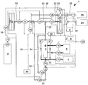
- FIG. 1 schematically shows the system diagram, the media flow and the arrangement of the individual sensors, actuators and valves of an impregnation device 1 with a monitoring and control system. 2
- the impregnation device 1 with the central molding device 3 as an impregnation tool educated Suitable impregnating agents for this application suitable synthetic resins or epoxy resins are used.
- TVPI Tempo Vacuum Pressure Impregnation
- the impregnation tool is here preferably designed for impregnating stator bars for generators in the power range from about 50 MW to 1700 MW and can have a tool length of between about 1 m and 15 m, depending on the rod length.
- the monitoring and control system 2 (sensor control system) according to the invention enables constant monitoring and precise control of the entire impregnation process. Furthermore, all individual process steps can be recorded, evaluated and stored on a storage medium.
- monitoring and control system 2 to extend a remote access (remote control) and the graphical monitoring of the manufacturing process by means of a web interface.
- a copy protection via a MAC address is additionally provided.
- the start conditions of the impregnation device 1 and its operating environment are measured and stored. These parameter values are recorded over the entire production cycle and are also available for later comparisons and evaluations. These are preferably the humidity with a humidity sensor 23, the vacuum pressure in the system and in the molding device 3 with a pressure sensor 14, the N 2 pressure in the system, the temperatures of the indoor air, the resin and the heat transfer oil of the heating or tempering 5 with temperature sensors 18, such as with commercially available PT100 rod temperature sensors.
- the "Emergency Stop" button is pressed, the complete shutdown of the system is tested and all valves are closed.
- the individual status displays are made via the color functions of illuminated displays on a touchpad.
- the starting of the impregnating device 1 begins with the opening of the forming device 3 or the impregnating tool TVPI with the hydraulic unit 7.
- the operating pressure of the hydraulic unit 7 is detected with a pressure sensor 12, such as an electronic pressure switch PN5001.
- a pressure sensor 12 such as an electronic pressure switch PN5001.
- the hydraulic cylinders are extended and this status is indicated by the status display.
- stator bars are placed by the operator with a gantry crane in the lower mold part and placed the upper mold part by means of bridge crane on the lower part. Thereafter, all hydraulic rams must be secured with a gate valve. The gate valves and the correctly inserted stator bars are to be confirmed after optical control on the touchpad.
- the molding device 3 By adjusting the temperature of the tempering device 5, the molding device 3 is preheated to about 50 ° C and simultaneously evacuated via the vacuum pump 28 of the vacuum device 6, the molding device 3 via a suction line 32 to preferably less than 1 mbar.
- the valves V1, V3, V6, V8 and, preferably, V4 ( Fig. 1 ) are open. Via a further suction line 33, a material container 29 is likewise evacuated. Any residual moisture in the stator bar and in the insulation (mica tape / fiberglass tape) is removed via the vacuum.
- the valve monitoring of the individual circuits is activated, ie the valves of the vacuum circuit (V1, V3, V6 and V8 and, preferably, V4) are open.
- the valve V2 of the impregnation agent line 22 and the valve V7 of the N2 pressure line 35 are closed.
- the N 2 pressure line 35 may include a pressure sensor 15.
- the valve V5 is also closed.
- the individual process steps and positions of the valve devices are controlled, recorded and logged by the electronic control device 8.
- valve V1 is closed and the valve V2 is opened. Due to the negative pressure in the evacuated molding apparatus 3, the impregnating resin is now sucked into its interior.
- the valve V4 is open and the valve V3 is closed.
- Valve V6 may be open or closed.
- the impregnating agent is sucked into the impregnating chamber 4 only on the basis of the negative pressure generated in the impregnating chamber 4. The evacuation is ended in this case before filling the molding apparatus 3 with the impregnating agent, which can be done by closing the valve V8 and / or interrupting the operation of the vacuum pump 28.
- the vacuum tank 37 ensures that even when the valve V8 is closed and / or when the vacuum pump 28 is not operating, a sufficient vacuum level is maintained in the impregnating chamber 4, which leads to the suction of the impregnating resin. In principle, however, it can also be provided that the vacuum pump 28 continues to be operated when the valves V8 and V4 are open in order to assist the suction of the impregnating agent into the impregnating chamber 4.
- the molding device 3 is filled on one side so far with resin, wherein the resin finally exits on the other side of the molding device 3 and the impregnation tool TVPI (Temperature Vacuum Pressure Impregnation) and wherein this state is detected by a capacitive sensor 16 and to the electronic control device 8, which opens valve V3 and closes valves V4, V6 and, preferably, V8. Valve V2 remains open. The valve V1 is closed. Also in these steps, the position of the involved valves is monitored and possibly reported faults immediately. If malfunctions occur, an "emergency stop" program is provided between each process step so that the system switches off completely and all valves V1 to V8 close.
- TVPI Tempo Vacuum Pressure Impregnation
- the molding device 3 further comprises a proximity sensor 19 and / or a level sensor 20, which is provided for level monitoring of the resin and is coupled to the valve control.
- a capacitive sensor can be provided as a proximity switch, such as the KQ6005.
- the valve monitoring checks whether the valves V6 and, preferably, V8 of the vacuum circuit and the valve V4 of the suction line 32 are closed, and the valve V7 of the pressure line 35 (N2) and the valve V3 of the bypass line 34 are open.
- a pressure sensor 15 usable to preferably 25 bar, in particular a PG2793, is used.
- a material container 29 is flooded as a feed container for the impregnating agent with N 2 gas from an N 2 port 25 and held under a pressure of, for example, about 6 bar. This ensures that all capillaries of the component to be impregnated are filled or sealed with resin.
- the impregnating agent line 22 and the bypass line 34 must also be maintained with N2 under a pressure of about 6 bar.
- valve V3 and the valve V7 is opened to the N2 gas cylinders 31 and the valve V4 is closed. This results in a holding of the resin at the inlet side and at the outlet side of the molding device 3 via the impregnating agent line 22, the bypass line 34 and the part of the suction line 32 adjoining the molding device 3.
- a microwave sensor 11 may also be provided on the material container 29.
- the microwave sensor 11 as LR3000 and a scale 27 may be formed as Industriewaage CH3G-150IG-H satorius.
- the material container 29 is filled with the impregnating agent from a material depot 26 for impregnating agent. So that no resin passes through the valve V6 in the vacuum device 6 and the vacuum pump 28, the filling amount of the material container 29 is determined with the balance 27. When a certain capacity is reached, the valve V5 is automatically closed by the controller 8. This ensures that always the same amount of filling passes into the material container 29 and thus into the molding device 3.
- the molding device 3 is now heated to 140-160 ° C within 1-2 hours.
- the temperature is controlled by temperature sensors 18. This temperature is held for the next curing process of the resin for about 6 hours.
- a viscosity or physical state sensor which is used in the molding apparatus 3 and which does not show the state of aggregation of the resin detected, reports to the electronic control device 8 and can be used to achieve a reduction of the process time when the intended values are reached.
- the mold temperature is reduced again to about 50 ° C, which corresponds approximately to a 4-hour cooling phase.
- press button 30 "open mold”.
- the top mold is then stored by bridge crane in a storage device.
- To shut down the hydraulic cylinders two buttons on the display and input device of two operators are operated simultaneously.
- the slide control is carried out by way sensor 21, the cylinders are in the status "extended", which is detected by the pressure detection on the hydraulic unit 7 by means of pressure sensor 12, such as a PN5001.
- stator bars are then removed with a crane from the forming device 3.
- the tangent delta value is measured on the stator bar. This is in this method in the lower tolerance range.
- the lower tool part, as well as all tubes, seals, vacuum channels, the vacuum tank 37 of the vacuum device 6 and the resin reservoir must be checked, if necessary cleaned and replaced.
- the next impregnation cycle is now started by re-supplying impregnation agent through a control command input to the display and input device 9.
- the valves V5, V6 and V8 are opened and the vacuum pump 28 is put into operation.
- the checking of the filling level or degree of filling of the material container 29 takes place, for example, via an (ultrasonic) flow sensor 17, a filling level sensor 20 and the scale 27.
- the filling level during vacuum filling and after completion of the impregnating process of the shaping device 3 is preferably stored as a reference value and then serves as standard filling size for the next processing cycle.
- valves V1 to V8 via compressed air of a compressed air connection 24.
- a pressure sensor 13 may be provided for compressed air.
- the impregnation device 1 is shut down with appropriate command input to the display and input device 9 to the electronic control device 8.
- the measurement data supplied by the measuring devices can be stored, linked and evaluated via an arbitrarily selected time axis, the archived data being protected against unauthorized access via serial number of the hardware and source code on the control become.
- the storage can advantageously be done in a memory card (flashcard).
- the control and monitoring program implemented in the electronic control device 8 is preferably encrypted according to a MAC address of the CAN bus system.
- the present invention has over the prior art in particular the advantage that is excluded by the closed molding device TVPI (Temperature Vacuum Pressure Impregnation) and their safe and monitored by numerous sensors manufacturing process emission of impregnating agent, in particular resin emission and styrene emission in the environment , as well as numerous possible sources of error are detected in good time and minimized or excluded.
- the impregnation time is drastically shortened, the resin consumption and the cleaning time are reduced to a minimum and a consistent quality of the impregnation is ensured.
- the sensors arranged at critical interfaces of the impregnation device 1 detect numerous processing parameters and, on the basis of these, permit reliable process management, which ultimately leads to a reduction of rejects and savings in costs.
- the recorded data can additionally be stored, processed and used for process optimization.
- Another advantage of this invention is that the provision of the impregnation tools TVPI (Temperature Vacuum Pressure Impregnation) compared to conventional methods can be done much faster and cheaper and the impregnation of a generator winding can be planned and executed time more accurate and faster.
- TVPI Temporal Vacuum Pressure Impregnation
Landscapes
- Engineering & Computer Science (AREA)
- Manufacturing & Machinery (AREA)
- Power Engineering (AREA)
- Manufacture Of Motors, Generators (AREA)
- Insulating Of Coils (AREA)
Priority Applications (1)
| Application Number | Priority Date | Filing Date | Title |
|---|---|---|---|
| PL12712063T PL2684100T3 (pl) | 2011-03-09 | 2012-03-08 | Sposób impregnacji i urządzenie do impregnacji |
Applications Claiming Priority (2)
| Application Number | Priority Date | Filing Date | Title |
|---|---|---|---|
| DE102011013439A DE102011013439A1 (de) | 2011-03-09 | 2011-03-09 | Überwachungs- und Steuersystem für eine Imprägniereinrichtung |
| PCT/EP2012/001033 WO2012119774A2 (de) | 2011-03-09 | 2012-03-08 | Imprägnierverfahren und imprägniereinrichtung |
Publications (2)
| Publication Number | Publication Date |
|---|---|
| EP2684100A2 EP2684100A2 (de) | 2014-01-15 |
| EP2684100B1 true EP2684100B1 (de) | 2018-04-25 |
Family
ID=45929486
Family Applications (1)
| Application Number | Title | Priority Date | Filing Date |
|---|---|---|---|
| EP12712063.2A Active EP2684100B1 (de) | 2011-03-09 | 2012-03-08 | Imprägnierverfahren und imprägniereinrichtung |
Country Status (4)
| Country | Link |
|---|---|
| EP (1) | EP2684100B1 (pl) |
| DE (2) | DE202011110399U1 (pl) |
| PL (1) | PL2684100T3 (pl) |
| WO (1) | WO2012119774A2 (pl) |
Families Citing this family (6)
| Publication number | Priority date | Publication date | Assignee | Title |
|---|---|---|---|---|
| DE102013019051A1 (de) | 2013-10-18 | 2015-04-23 | Pett & Pett T.I.P GmbH | Vorrichtung zum Imprägnieren von Wicklungsstäben für elektrische Maschinen |
| DE202013010299U1 (de) | 2013-10-18 | 2015-01-21 | Pett & Pett T.I.P GmbH | Vorrichtung zum Imprägnieren von Wicklungsstäben für elektrische Maschinen |
| RU2597892C1 (ru) * | 2015-03-11 | 2016-09-20 | Федеральное государственное бюджетное образовательное учреждение высшего профессионального образования "Томский государственный университет систем управления и радиоэлектроники" | Способ пропитки и сушки обмоток электрических машин |
| RU2597890C1 (ru) * | 2015-03-11 | 2016-09-20 | Федеральное государственное бюджетное образовательное учреждение высшего профессионального образования "Томский государственный университет систем управления и радиоэлектроники" | Способ пропитки обмоток электрических машин |
| DE102016005320A1 (de) * | 2016-01-20 | 2017-07-20 | Pett & P.E.T.T. Trade & Industry Products Gmbh | Werkzeug und Verfahren zum Imprägnieren und Aushärten von Wicklungsisolierungen von elektrischen Bauteilen |
| US12278531B2 (en) * | 2021-05-10 | 2025-04-15 | The Timken Company | Vacuum pressure impregnation method for insulation system |
Citations (1)
| Publication number | Priority date | Publication date | Assignee | Title |
|---|---|---|---|---|
| CN101964570A (zh) * | 2010-10-29 | 2011-02-02 | 山东齐鲁电机制造有限公司 | 电机定子线棒模具式真空压力浸漆绝缘装置 |
Family Cites Families (7)
| Publication number | Priority date | Publication date | Assignee | Title |
|---|---|---|---|---|
| DE3901230C1 (pl) | 1989-01-17 | 1990-07-05 | Siemens Ag, 1000 Berlin Und 8000 Muenchen, De | |
| DE4125137C2 (de) * | 1991-07-30 | 1995-06-14 | Icos Ges Fuer Ind Communicatio | Steuerpult für Bearbeitungs- und Meßmaschinen |
| US5723920A (en) | 1994-10-12 | 1998-03-03 | General Electric Company | Stator bars internally graded with conductive binder tape |
| DE19822433C2 (de) | 1998-05-19 | 2003-11-20 | Maschb Gottlob Thumm Gmbh | Verfahren und Vorrichtung zum Imprägnieren von Wicklungen |
| DE19835361A1 (de) | 1998-08-05 | 2000-02-10 | Abb Patent Gmbh | Verfahren und Vorrichtung zum Imprägnieren von Leiterstäben für die Statorwicklung einer elektrischen Maschine |
| JP4160399B2 (ja) * | 2001-03-01 | 2008-10-01 | フィッシャー−ローズマウント システムズ, インコーポレイテッド | プロセスプラント内の指標の作成と表示 |
| DE10346629A1 (de) * | 2003-10-08 | 2005-05-19 | Reinhard Keller | Steuerung für eine Maschine zur Herstellung von Papier-Polstern |
-
2011
- 2011-03-09 DE DE202011110399U patent/DE202011110399U1/de not_active Expired - Lifetime
- 2011-03-09 DE DE102011013439A patent/DE102011013439A1/de not_active Ceased
-
2012
- 2012-03-08 EP EP12712063.2A patent/EP2684100B1/de active Active
- 2012-03-08 WO PCT/EP2012/001033 patent/WO2012119774A2/de not_active Ceased
- 2012-03-08 PL PL12712063T patent/PL2684100T3/pl unknown
Patent Citations (1)
| Publication number | Priority date | Publication date | Assignee | Title |
|---|---|---|---|---|
| CN101964570A (zh) * | 2010-10-29 | 2011-02-02 | 山东齐鲁电机制造有限公司 | 电机定子线棒模具式真空压力浸漆绝缘装置 |
Also Published As
| Publication number | Publication date |
|---|---|
| EP2684100A2 (de) | 2014-01-15 |
| DE202011110399U1 (de) | 2013-11-26 |
| PL2684100T3 (pl) | 2018-09-28 |
| DE102011013439A1 (de) | 2012-09-13 |
| WO2012119774A3 (de) | 2015-04-09 |
| WO2012119774A2 (de) | 2012-09-13 |
Similar Documents
| Publication | Publication Date | Title |
|---|---|---|
| EP2684100A2 (de) | Imprägnierverfahren und imprägniereinrichtung | |
| EP3137285B1 (de) | Pulverbettbasiertes additives fertigungsverfahren und anlage zur durchführung dieses verfahrens | |
| EP3053675B1 (de) | Pulverauftragseinheit, entsprechende vorrichtung und verwendung einer pulverauftragseinheit | |
| EP1254501A1 (de) | Verfahren zur herstellung einer hochwertigen isolierung von elektrischen leitern oder leiterbündeln rotierender elektrischer maschinen mittels thermischen spritzens | |
| EP3073615A1 (de) | Selbstklebende nutverschlussvorrichtung für eine elektrische maschine | |
| EP2746758A1 (de) | Verfahren und Vorrichtung zur Bestimmung des Feuchtegehalts und zum Trocknen einer Isolierung | |
| DE102011075425A1 (de) | Verfahren zum Herstellen eines elektrischen Isolationssystems für eine elektrische Maschine | |
| EP0898806A1 (de) | Trägerkörper für eine elektrische wicklung und verfahren zur herstellung eines glimmschutzes | |
| EP1240705A1 (de) | Einrichtung zum imprägnieren einer isolation eines wicklungsstabes einer elektrischen maschine | |
| DE102006040049A1 (de) | Verfahren und Vorrichtung zum Vorformen von Kohlenstofffaser-Halbzeugen für die Herstellung von Faserverbundbauteilen | |
| DE102008005234B4 (de) | Vorrichtung und Verfahren zur Wärmebehandlung von Integralrotoren von Gasturbinen | |
| DE102013019051A1 (de) | Vorrichtung zum Imprägnieren von Wicklungsstäben für elektrische Maschinen | |
| DE102015013526B3 (de) | Vorrichtung und Verfahren zum Bewickeln eines Wicklungsträgers | |
| EP2961593B1 (de) | Verfahren zum vorheizen von mindestens einer form | |
| EP3791460B1 (de) | Elektrische maschine mit kunststoffschicht als phasentrenner | |
| DE3138766C2 (de) | Verfahren zur Herstellung von Hochspannungsisolierungen auf Wickelungselementen elektrischer Maschinen | |
| DE102008006056A1 (de) | Verfahren zur verbesserten Herstellung der Isolierung eines Leiterelementes für eine elektrische Maschine | |
| DE102019111726A1 (de) | Imprägniervorrichtung zum Imprägnieren von Körpern, insbesondere von Wickelgütern, Imprägnieranlage und Verfahren zum Betreiben mindestens einer Imprägniervorrichtung | |
| DE102011007037A1 (de) | Elektrische Stromerzeugungsanlage, insbesondere Windenergieanlage mit Synchrongenerator und Umrichter | |
| DE202013010299U1 (de) | Vorrichtung zum Imprägnieren von Wicklungsstäben für elektrische Maschinen | |
| DE102013208200A1 (de) | Verfahren und Vorrichtung zur Herstellung einer elektrischen Maschine | |
| DE60011752T2 (de) | Verfahren zur herstellung von strukturteilen aus composit-material nach dem harz-injektions-verfahren und vorrichtung zur durchführung des verfahrens | |
| CH700573A1 (de) | Vorrichtung und Verfahren zum Imprägnieren einer Isolierung eines Leiterstabs. | |
| CH382276A (de) | Nutisolation für die Leiterstäbe einer elektrischen Maschine | |
| DE29613492U1 (de) | Vorrichtung zum Imprägnieren von Wicklungen |
Legal Events
| Date | Code | Title | Description |
|---|---|---|---|
| PUAI | Public reference made under article 153(3) epc to a published international application that has entered the european phase |
Free format text: ORIGINAL CODE: 0009012 |
|
| 17P | Request for examination filed |
Effective date: 20130816 |
|
| AK | Designated contracting states |
Kind code of ref document: A2 Designated state(s): AL AT BE BG CH CY CZ DE DK EE ES FI FR GB GR HR HU IE IS IT LI LT LU LV MC MK MT NL NO PL PT RO RS SE SI SK SM TR |
|
| DAX | Request for extension of the european patent (deleted) | ||
| R17D | Deferred search report published (corrected) |
Effective date: 20150409 |
|
| RAP1 | Party data changed (applicant data changed or rights of an application transferred) |
Owner name: PETT & P.E.T.T. TRADE & INDUSTRY PRODUCTS GMBH |
|
| 17Q | First examination report despatched |
Effective date: 20160219 |
|
| STAA | Information on the status of an ep patent application or granted ep patent |
Free format text: STATUS: EXAMINATION IS IN PROGRESS |
|
| GRAP | Despatch of communication of intention to grant a patent |
Free format text: ORIGINAL CODE: EPIDOSNIGR1 |
|
| STAA | Information on the status of an ep patent application or granted ep patent |
Free format text: STATUS: GRANT OF PATENT IS INTENDED |
|
| INTG | Intention to grant announced |
Effective date: 20170929 |
|
| GRAS | Grant fee paid |
Free format text: ORIGINAL CODE: EPIDOSNIGR3 |
|
| GRAA | (expected) grant |
Free format text: ORIGINAL CODE: 0009210 |
|
| STAA | Information on the status of an ep patent application or granted ep patent |
Free format text: STATUS: THE PATENT HAS BEEN GRANTED |
|
| AK | Designated contracting states |
Kind code of ref document: B1 Designated state(s): AL AT BE BG CH CY CZ DE DK EE ES FI FR GB GR HR HU IE IS IT LI LT LU LV MC MK MT NL NO PL PT RO RS SE SI SK SM TR |
|
| REG | Reference to a national code |
Ref country code: GB Ref legal event code: FG4D Free format text: NOT ENGLISH |
|
| REG | Reference to a national code |
Ref country code: CH Ref legal event code: EP |
|
| REG | Reference to a national code |
Ref country code: AT Ref legal event code: REF Ref document number: 993556 Country of ref document: AT Kind code of ref document: T Effective date: 20180515 |
|
| REG | Reference to a national code |
Ref country code: IE Ref legal event code: FG4D Free format text: LANGUAGE OF EP DOCUMENT: GERMAN |
|
| REG | Reference to a national code |
Ref country code: DE Ref legal event code: R096 Ref document number: 502012012590 Country of ref document: DE |
|
| REG | Reference to a national code |
Ref country code: NL Ref legal event code: MP Effective date: 20180425 |
|
| REG | Reference to a national code |
Ref country code: LT Ref legal event code: MG4D |
|
| PG25 | Lapsed in a contracting state [announced via postgrant information from national office to epo] |
Ref country code: NL Free format text: LAPSE BECAUSE OF FAILURE TO SUBMIT A TRANSLATION OF THE DESCRIPTION OR TO PAY THE FEE WITHIN THE PRESCRIBED TIME-LIMIT Effective date: 20180425 |
|
| PG25 | Lapsed in a contracting state [announced via postgrant information from national office to epo] |
Ref country code: SE Free format text: LAPSE BECAUSE OF FAILURE TO SUBMIT A TRANSLATION OF THE DESCRIPTION OR TO PAY THE FEE WITHIN THE PRESCRIBED TIME-LIMIT Effective date: 20180425 Ref country code: LT Free format text: LAPSE BECAUSE OF FAILURE TO SUBMIT A TRANSLATION OF THE DESCRIPTION OR TO PAY THE FEE WITHIN THE PRESCRIBED TIME-LIMIT Effective date: 20180425 Ref country code: ES Free format text: LAPSE BECAUSE OF FAILURE TO SUBMIT A TRANSLATION OF THE DESCRIPTION OR TO PAY THE FEE WITHIN THE PRESCRIBED TIME-LIMIT Effective date: 20180425 Ref country code: BG Free format text: LAPSE BECAUSE OF FAILURE TO SUBMIT A TRANSLATION OF THE DESCRIPTION OR TO PAY THE FEE WITHIN THE PRESCRIBED TIME-LIMIT Effective date: 20180725 Ref country code: FI Free format text: LAPSE BECAUSE OF FAILURE TO SUBMIT A TRANSLATION OF THE DESCRIPTION OR TO PAY THE FEE WITHIN THE PRESCRIBED TIME-LIMIT Effective date: 20180425 Ref country code: NO Free format text: LAPSE BECAUSE OF FAILURE TO SUBMIT A TRANSLATION OF THE DESCRIPTION OR TO PAY THE FEE WITHIN THE PRESCRIBED TIME-LIMIT Effective date: 20180725 |
|
| PG25 | Lapsed in a contracting state [announced via postgrant information from national office to epo] |
Ref country code: GR Free format text: LAPSE BECAUSE OF FAILURE TO SUBMIT A TRANSLATION OF THE DESCRIPTION OR TO PAY THE FEE WITHIN THE PRESCRIBED TIME-LIMIT Effective date: 20180726 Ref country code: LV Free format text: LAPSE BECAUSE OF FAILURE TO SUBMIT A TRANSLATION OF THE DESCRIPTION OR TO PAY THE FEE WITHIN THE PRESCRIBED TIME-LIMIT Effective date: 20180425 Ref country code: RS Free format text: LAPSE BECAUSE OF FAILURE TO SUBMIT A TRANSLATION OF THE DESCRIPTION OR TO PAY THE FEE WITHIN THE PRESCRIBED TIME-LIMIT Effective date: 20180425 Ref country code: HR Free format text: LAPSE BECAUSE OF FAILURE TO SUBMIT A TRANSLATION OF THE DESCRIPTION OR TO PAY THE FEE WITHIN THE PRESCRIBED TIME-LIMIT Effective date: 20180425 |
|
| PG25 | Lapsed in a contracting state [announced via postgrant information from national office to epo] |
Ref country code: PT Free format text: LAPSE BECAUSE OF FAILURE TO SUBMIT A TRANSLATION OF THE DESCRIPTION OR TO PAY THE FEE WITHIN THE PRESCRIBED TIME-LIMIT Effective date: 20180827 |
|
| REG | Reference to a national code |
Ref country code: DE Ref legal event code: R097 Ref document number: 502012012590 Country of ref document: DE |
|
| PG25 | Lapsed in a contracting state [announced via postgrant information from national office to epo] |
Ref country code: RO Free format text: LAPSE BECAUSE OF FAILURE TO SUBMIT A TRANSLATION OF THE DESCRIPTION OR TO PAY THE FEE WITHIN THE PRESCRIBED TIME-LIMIT Effective date: 20180425 Ref country code: CZ Free format text: LAPSE BECAUSE OF FAILURE TO SUBMIT A TRANSLATION OF THE DESCRIPTION OR TO PAY THE FEE WITHIN THE PRESCRIBED TIME-LIMIT Effective date: 20180425 Ref country code: EE Free format text: LAPSE BECAUSE OF FAILURE TO SUBMIT A TRANSLATION OF THE DESCRIPTION OR TO PAY THE FEE WITHIN THE PRESCRIBED TIME-LIMIT Effective date: 20180425 Ref country code: SK Free format text: LAPSE BECAUSE OF FAILURE TO SUBMIT A TRANSLATION OF THE DESCRIPTION OR TO PAY THE FEE WITHIN THE PRESCRIBED TIME-LIMIT Effective date: 20180425 Ref country code: DK Free format text: LAPSE BECAUSE OF FAILURE TO SUBMIT A TRANSLATION OF THE DESCRIPTION OR TO PAY THE FEE WITHIN THE PRESCRIBED TIME-LIMIT Effective date: 20180425 |
|
| PG25 | Lapsed in a contracting state [announced via postgrant information from national office to epo] |
Ref country code: SM Free format text: LAPSE BECAUSE OF FAILURE TO SUBMIT A TRANSLATION OF THE DESCRIPTION OR TO PAY THE FEE WITHIN THE PRESCRIBED TIME-LIMIT Effective date: 20180425 |
|
| PLBE | No opposition filed within time limit |
Free format text: ORIGINAL CODE: 0009261 |
|
| STAA | Information on the status of an ep patent application or granted ep patent |
Free format text: STATUS: NO OPPOSITION FILED WITHIN TIME LIMIT |
|
| 26N | No opposition filed |
Effective date: 20190128 |
|
| PGFP | Annual fee paid to national office [announced via postgrant information from national office to epo] |
Ref country code: IE Payment date: 20190211 Year of fee payment: 6 Ref country code: IT Payment date: 20190325 Year of fee payment: 8 |
|
| PG25 | Lapsed in a contracting state [announced via postgrant information from national office to epo] |
Ref country code: SI Free format text: LAPSE BECAUSE OF FAILURE TO SUBMIT A TRANSLATION OF THE DESCRIPTION OR TO PAY THE FEE WITHIN THE PRESCRIBED TIME-LIMIT Effective date: 20180425 |
|
| PG25 | Lapsed in a contracting state [announced via postgrant information from national office to epo] |
Ref country code: MC Free format text: LAPSE BECAUSE OF FAILURE TO SUBMIT A TRANSLATION OF THE DESCRIPTION OR TO PAY THE FEE WITHIN THE PRESCRIBED TIME-LIMIT Effective date: 20180425 |
|
| REG | Reference to a national code |
Ref country code: CH Ref legal event code: PL |
|
| GBPC | Gb: european patent ceased through non-payment of renewal fee |
Effective date: 20190308 |
|
| PG25 | Lapsed in a contracting state [announced via postgrant information from national office to epo] |
Ref country code: AL Free format text: LAPSE BECAUSE OF FAILURE TO SUBMIT A TRANSLATION OF THE DESCRIPTION OR TO PAY THE FEE WITHIN THE PRESCRIBED TIME-LIMIT Effective date: 20180425 Ref country code: LU Free format text: LAPSE BECAUSE OF NON-PAYMENT OF DUE FEES Effective date: 20190308 |
|
| REG | Reference to a national code |
Ref country code: BE Ref legal event code: MM Effective date: 20190331 |
|
| PG25 | Lapsed in a contracting state [announced via postgrant information from national office to epo] |
Ref country code: IE Free format text: LAPSE BECAUSE OF NON-PAYMENT OF DUE FEES Effective date: 20190308 Ref country code: LI Free format text: LAPSE BECAUSE OF NON-PAYMENT OF DUE FEES Effective date: 20190331 Ref country code: CH Free format text: LAPSE BECAUSE OF NON-PAYMENT OF DUE FEES Effective date: 20190331 Ref country code: GB Free format text: LAPSE BECAUSE OF NON-PAYMENT OF DUE FEES Effective date: 20190308 |
|
| PG25 | Lapsed in a contracting state [announced via postgrant information from national office to epo] |
Ref country code: BE Free format text: LAPSE BECAUSE OF NON-PAYMENT OF DUE FEES Effective date: 20190331 Ref country code: FR Free format text: LAPSE BECAUSE OF NON-PAYMENT OF DUE FEES Effective date: 20190331 |
|
| PG25 | Lapsed in a contracting state [announced via postgrant information from national office to epo] |
Ref country code: TR Free format text: LAPSE BECAUSE OF FAILURE TO SUBMIT A TRANSLATION OF THE DESCRIPTION OR TO PAY THE FEE WITHIN THE PRESCRIBED TIME-LIMIT Effective date: 20180425 |
|
| PG25 | Lapsed in a contracting state [announced via postgrant information from national office to epo] |
Ref country code: MT Free format text: LAPSE BECAUSE OF FAILURE TO SUBMIT A TRANSLATION OF THE DESCRIPTION OR TO PAY THE FEE WITHIN THE PRESCRIBED TIME-LIMIT Effective date: 20180425 |
|
| REG | Reference to a national code |
Ref country code: AT Ref legal event code: MM01 Ref document number: 993556 Country of ref document: AT Kind code of ref document: T Effective date: 20190308 |
|
| PG25 | Lapsed in a contracting state [announced via postgrant information from national office to epo] |
Ref country code: AT Free format text: LAPSE BECAUSE OF NON-PAYMENT OF DUE FEES Effective date: 20190308 |
|
| PG25 | Lapsed in a contracting state [announced via postgrant information from national office to epo] |
Ref country code: CY Free format text: LAPSE BECAUSE OF FAILURE TO SUBMIT A TRANSLATION OF THE DESCRIPTION OR TO PAY THE FEE WITHIN THE PRESCRIBED TIME-LIMIT Effective date: 20180425 |
|
| PG25 | Lapsed in a contracting state [announced via postgrant information from national office to epo] |
Ref country code: IS Free format text: LAPSE BECAUSE OF FAILURE TO SUBMIT A TRANSLATION OF THE DESCRIPTION OR TO PAY THE FEE WITHIN THE PRESCRIBED TIME-LIMIT Effective date: 20180825 |
|
| PG25 | Lapsed in a contracting state [announced via postgrant information from national office to epo] |
Ref country code: HU Free format text: LAPSE BECAUSE OF FAILURE TO SUBMIT A TRANSLATION OF THE DESCRIPTION OR TO PAY THE FEE WITHIN THE PRESCRIBED TIME-LIMIT; INVALID AB INITIO Effective date: 20120308 |
|
| PG25 | Lapsed in a contracting state [announced via postgrant information from national office to epo] |
Ref country code: IT Free format text: LAPSE BECAUSE OF NON-PAYMENT OF DUE FEES Effective date: 20200308 |
|
| PG25 | Lapsed in a contracting state [announced via postgrant information from national office to epo] |
Ref country code: PL Free format text: LAPSE BECAUSE OF NON-PAYMENT OF DUE FEES Effective date: 20200308 |
|
| PG25 | Lapsed in a contracting state [announced via postgrant information from national office to epo] |
Ref country code: MK Free format text: LAPSE BECAUSE OF FAILURE TO SUBMIT A TRANSLATION OF THE DESCRIPTION OR TO PAY THE FEE WITHIN THE PRESCRIBED TIME-LIMIT Effective date: 20180425 |
|
| PGFP | Annual fee paid to national office [announced via postgrant information from national office to epo] |
Ref country code: DE Payment date: 20260320 Year of fee payment: 15 |