EP2684111B1 - Berührungsempfindliche vorrichtung - Google Patents
Berührungsempfindliche vorrichtung Download PDFInfo
- Publication number
- EP2684111B1 EP2684111B1 EP09817589.6A EP09817589A EP2684111B1 EP 2684111 B1 EP2684111 B1 EP 2684111B1 EP 09817589 A EP09817589 A EP 09817589A EP 2684111 B1 EP2684111 B1 EP 2684111B1
- Authority
- EP
- European Patent Office
- Prior art keywords
- panel
- sensing area
- vibration exciters
- touch sensitive
- bending waves
- Prior art date
- Legal status (The legal status is an assumption and is not a legal conclusion. Google has not performed a legal analysis and makes no representation as to the accuracy of the status listed.)
- Active
Links
Images









Classifications
-
- H—ELECTRICITY
- H01—ELECTRIC ELEMENTS
- H01H—ELECTRIC SWITCHES; RELAYS; SELECTORS; EMERGENCY PROTECTIVE DEVICES
- H01H13/00—Switches having rectilinearly-movable operating part or parts adapted for pushing or pulling in one direction only, e.g. push-button switch
- H01H13/02—Details
- H01H13/12—Movable parts; Contacts mounted thereon
- H01H13/14—Operating parts, e.g. push-button
-
- G—PHYSICS
- G06—COMPUTING OR CALCULATING; COUNTING
- G06F—ELECTRIC DIGITAL DATA PROCESSING
- G06F3/00—Input arrangements for transferring data to be processed into a form capable of being handled by the computer; Output arrangements for transferring data from processing unit to output unit, e.g. interface arrangements
- G06F3/01—Input arrangements or combined input and output arrangements for interaction between user and computer
- G06F3/016—Input arrangements with force or tactile feedback as computer generated output to the user
-
- G—PHYSICS
- G06—COMPUTING OR CALCULATING; COUNTING
- G06F—ELECTRIC DIGITAL DATA PROCESSING
- G06F3/00—Input arrangements for transferring data to be processed into a form capable of being handled by the computer; Output arrangements for transferring data from processing unit to output unit, e.g. interface arrangements
- G06F3/01—Input arrangements or combined input and output arrangements for interaction between user and computer
- G06F3/03—Arrangements for converting the position or the displacement of a member into a coded form
- G06F3/041—Digitisers, e.g. for touch screens or touch pads, characterised by the transducing means
- G06F3/0416—Control or interface arrangements specially adapted for digitisers
-
- G—PHYSICS
- G06—COMPUTING OR CALCULATING; COUNTING
- G06F—ELECTRIC DIGITAL DATA PROCESSING
- G06F3/00—Input arrangements for transferring data to be processed into a form capable of being handled by the computer; Output arrangements for transferring data from processing unit to output unit, e.g. interface arrangements
- G06F3/01—Input arrangements or combined input and output arrangements for interaction between user and computer
- G06F3/03—Arrangements for converting the position or the displacement of a member into a coded form
- G06F3/041—Digitisers, e.g. for touch screens or touch pads, characterised by the transducing means
- G06F3/0416—Control or interface arrangements specially adapted for digitisers
- G06F3/04166—Details of scanning methods, e.g. sampling time, grouping of sub areas or time sharing with display driving
-
- G—PHYSICS
- G06—COMPUTING OR CALCULATING; COUNTING
- G06F—ELECTRIC DIGITAL DATA PROCESSING
- G06F3/00—Input arrangements for transferring data to be processed into a form capable of being handled by the computer; Output arrangements for transferring data from processing unit to output unit, e.g. interface arrangements
- G06F3/01—Input arrangements or combined input and output arrangements for interaction between user and computer
- G06F3/03—Arrangements for converting the position or the displacement of a member into a coded form
- G06F3/041—Digitisers, e.g. for touch screens or touch pads, characterised by the transducing means
- G06F3/0416—Control or interface arrangements specially adapted for digitisers
- G06F3/0418—Control or interface arrangements specially adapted for digitisers for error correction or compensation, e.g. based on parallax, calibration or alignment
-
- G—PHYSICS
- G06—COMPUTING OR CALCULATING; COUNTING
- G06F—ELECTRIC DIGITAL DATA PROCESSING
- G06F3/00—Input arrangements for transferring data to be processed into a form capable of being handled by the computer; Output arrangements for transferring data from processing unit to output unit, e.g. interface arrangements
- G06F3/01—Input arrangements or combined input and output arrangements for interaction between user and computer
- G06F3/03—Arrangements for converting the position or the displacement of a member into a coded form
- G06F3/041—Digitisers, e.g. for touch screens or touch pads, characterised by the transducing means
- G06F3/043—Digitisers, e.g. for touch screens or touch pads, characterised by the transducing means using propagating acoustic waves
-
- H—ELECTRICITY
- H01—ELECTRIC ELEMENTS
- H01H—ELECTRIC SWITCHES; RELAYS; SELECTORS; EMERGENCY PROTECTIVE DEVICES
- H01H13/00—Switches having rectilinearly-movable operating part or parts adapted for pushing or pulling in one direction only, e.g. push-button switch
- H01H13/70—Switches having rectilinearly-movable operating part or parts adapted for pushing or pulling in one direction only, e.g. push-button switch having a plurality of operating members associated with different sets of contacts, e.g. keyboard
Definitions
- the invention relates to touch sensitive devices including touch sensitive screens or panels.
- US 4,885,565 , US 5,638,060 , US 5,977,867 , US 2002/0075135 A1 describe touch-operated apparatus having tactile feedback for a user when touched.
- an actuator is provided for imparting motion to the CRT when the actuator is energised to provide tactile feedback.
- a voltage is applied to a piezo-electric element which form a switch to vibrate the element to apply a reaction force to a user's finger.
- a tactile feedback unit generates a mechanical vibration sensed by the user when the touch screen is touched with a finger or a pointer.
- US 2002/0075135 A1 describes the use of a second transducer to provide a pulse in the form of transient spike to simulate a button click.
- European patent application with publication no. EP 1 310 860 A1 discloses an electronic device that drives an oscillatory actuator to cause generation of vibration when it is detected that an operation input to a touch panel or operation key has been received.
- the electronic device increases an amplitude of the vibration generated at a touched position on the touch panel by mutual interference of oscillatory waves generated from a plurality of vibration generators.
- US 2007/002029 A1 discloses an information processing device including a touch panel, a detecting unit which detects a touched position on the touch panel, a control unit which generates a first drive signal and a second drive signal for vibrating the touched position detected by the detecting unit, a first vibration element provided on an end of the touch panel, and vibrating depending on the first drive signal and a second vibration element provided on an end of the touch panel, and vibrating depending on the second drive signal.
- the first and second vibration elements generate respective first and second waves and a phase difference between the two waves results in interference when the two waves overlap, thus generating an area of the touch panel with strong vibration and an area with weak vibration.
- tactile feedback is provided in response to a discrete touch of a user's finger or pointer.
- a touch sensitive device compromising a panel capable of supporting bending waves, a user-accessible touch sensitive screen on or forming part of a face of the panel, the touch sensitive screen having a plurality of different sensing areas, a plurality of vibration exciters coupled to the panel to apply bending waves to the panel to provide tactile feedback at the plurality of sensing areas in response to the user touching a sensing area, and signal processing means arranged to apply signals to the vibration exciters so as to steer bending waves applied to the panel by the plurality of vibration exciters whereby the amplitude of the applied bending waves is maximised at the sensing area touched by the user and reduced or minimised at each other sensing area.
- the signal processing means there is a wanted signal (the maximised vibration at one sensing area) and an unwanted signal (minimised vibration at another sensing area).
- the ratio of the two may be described as a “signal to noise ratio", or "SNR”. This is usually expressed in dB, and large values are better than small values.
- each sensing area or location receives primarily the haptics signal for that location, even when the locations are simultaneously contacted. Anywhere else on the panel will experience a combination of the signals, but this unimportant.
- this feature may be termed simultaneous dual region haptics since two simultaneous haptic feedbacks are provided at spatially separate locations. This may be extended to multiple signals and multiple regions to provide simultaneous multi-region haptics.
- the signal processing means may be arranged to apply bending wave signals having a small or minimal acoustic component. This may be desirable to ensure that the haptic signal provided to each location is silent.
- the panel may be intendedly resonant and wherein the signals applied by the vibration exciters cause the panel to resonant.
- the panel may be a resonant bending wave model panel as described in International Patent Application WO 97/09842 .
- the panel may also be a loudspeaker wherein a further vibration exciter excites vibration which produces an acoustic output.
- the vibration exciters may be a moving coil transducer and/or a piezoelectric bending transducer, for example one comprising a resonant element as described in e.g. in WO 01/54450 A2
- the exciters may/may not be inertial.
- the signal steering is such that the signal sensing area touched by the user is caused to be an antinodal and each other signal sensing area is caused to be nodal.
- a nodal point is one that no velocity at any frequency of excitation and an anti-nodal point has maximum velocity.
- the device may compromise n number of signal sensing areas and greater than n, e.g., n+1, number of vibration exciters.
- n e.g., n+1
- the amplitude of the applied bending waves is maximised to the greatest possible amplitude at the sensing area touched by the user and is approximately zero at each other sensing area.
- n nodal responses may be achieved.
- the requirement for "silent" may be considered equivalent to producing a nodal pressure on axis. To achieve silent dual region haptic feedback, it would be necessary to create both a nodal point, say at the other sensing area, and zero pressure on axis.
- n there may be n number of signal sensing areas and n or fewer than n number of vibration exciters.
- the maximum amplitude may be less than the greatest possible amplitude achieved with n+1 vibration exciters and/or the minimum may be significantly greater than zero.
- Such a solution may either do its best to achieve all desired nodal responses equally, or else achieve some better than others. In other words solving MR and silent haptics simultaneously may reduce both pressure and velocity responses, but not all the way to zero. To achieve an exact solution requires another a number of vibration exciters greater than n.
- nodal lines may be frequency dependent, changing shape at each mode in the system. Groups of nodes may be observed in order to reduce the motion along a line. If this line is naturally nodal over part of the frequency range, the method is more likely to be successful than for an arbitrary line.
- the nodal line may be steered away from a natural line of symmetry.
- 'm' input i.e. signals to be applied to m number of vibration exciters
- 'n' output i.e. n number of sensing areas or n-1 number of sensing areas and the desire for silent haptics
- the parallel "all at once" eigenvalue method and the serial “one at a time” eigenvalue method.
- a "tan theta” algorithm may be used to define the signals to be applied to the exciters.
- the signal processing means may apply signals to the vibration exciters so as simultaneously to provide tactile feedback at a plurality of the sensing areas.
- a method of operating a touch sensitive device comprising the steps of sensing an area of the screen touched by a user and processing and applying signals to the plurality of vibration exciters to steer bending waves in the panel whereby the amplitude of vibration is maximised at the sensing area touched by the user and reduced or minimised at each other sensing area.
- the signals applied to the vibration exciters may be processed so as simultaneously to provide tactile feedback to a plurality of sensing areas while reducing or minimising crosstalk between the sensing areas.
- Contact on the screen may be detected and/or tracked as described in International patent applications WO 01/48684 A2 , WO 03/005292 A1 , and/or WO 04/053781 A2 to the present applicant.
- the disclosure further provides processor control code to implement the above-described methods, in particular on a data carrier such as a disk, CD- or DVD-ROM, programmed memory such as read-only memory (Firmware), or on data carrier such as an optical or electrical signal carrier.
- Code (and/or data) to implement embodiments of the invention may compromise source, object or executable code in a conventional programming language (interpreted or compiled) such as C, or assembly code, code for setting up or controlling an ASIC (Application Specific Integrated Circuit) or FPGA (Field Programmable Gate Array), or code for a hardware description language such as Verilog (Trade Mark) or VHDL (Very high speed integrated circuit Hardware Description Language).
- a data carrier such as a disk, CD- or DVD-ROM, programmed memory such as read-only memory (Firmware), or on data carrier such as an optical or electrical signal carrier.
- Code (and/or data) to implement embodiments of the invention may compromise source, object or executable code in a conventional programming language (interpreted or
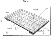
- Figure 1a shows a model of a touch sensitive device 10 comprising a touch sensitive screen 12 mounted on a gasket 14.
- Two vibration exciters 16, 18 in the form of DMAs are provided to generate a signal within the screen.
- One or more sensors are used to detect a touch or movement of the stylus on the screen.
- external air is modelled explicitly to 10 cm, and implicitly to infinity.
- the two exciters were each crudely simulated by point sources and a frequency dependent force. Both the panel itself, and the placement of the DMAs have asymmetry in one axis or the other.
- forces are applied separately to drive-points RP-1 (driven by the first exciter 16) and RP-2 (driven by the second exciter 18). The responses at all points in the system are calculated.
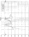
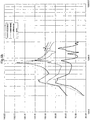
- Figure 2a shows the velocity responses (transadmittance) against frequency for each input at a particular output node (node 22) on the outer surface.
- the box around node 22 shown in Figure 1a defines a first sensing area.
- the dB scale is relative to 1 m/s/N. Below about 350 - 400 Hz the responses from each input are quite similar, but at higher frequencies they separate.
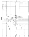
- Figure 2b shows the velocity responses (transadmittance) against frequency for each input at a second output node (node 44) on the outer surface.
- the box around node 44 shown in Figure 1a defines a second sensing area.
- the responses at this node are of a similar character, but different in detail, to those at node 22.
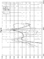
- Figure 2c shows the sound pressure level against frequency for each input at 10cm on axis. In each Figure, the real part of the signal is shown as a solid line and the imaginary part as a dotted line.
- a haptics signal provides tactile feedback to a user of the touch sensitive screen.
- this may be achieved by ensuring that when points A and B are simultaneously contacted, the transfer functions for the signals applied to the first and second exciters 16,18 produce a node at A and the required haptics signal at point B and produce a node at point B and the required haptics signal at point A.
- the transfer functions necessary to produce a node at the other touch point are obtained, and these used to provide the appropriate haptic signal.
- a nodal point is one that has no velocity at any frequency of excitation.
- FIG. 3b is a block diagram showing the key processing elements of the system.
- Contacts on the touch screen 12 are detected by one or more sensors 17 and the output from the sensors 17 is fed to a processor 20.
- the processor determines the signals to be applied to the exciters 16,18 as explained in more detail below. These signals are applied to the exciters using a signal generator 22. It will be appreciated that although the signal generator and processor are shown as separate entities, the processor functionality may be incorporated into the signal generator functionality.
- the exciters 16,18 apply bending wave vibration to the touch screen.
- each touch point receives only its intended haptic signal. Anywhere else on the panel will experience a combination of the signals, but this is unimportant.
- This feature may be termed simultaneous dual region haptics since two simultaneous haptic feedbacks are provided at spatially separate locations. This may be extended to multiple signals and multiple regions to provide simultaneous multi-region haptics.
- M s f . M 1 + M 2 , where M1 and M2 are the individual error measures for velocity and pressure respectively.
- n+1 input channels are required (it is useful to consider the requirement for "silent" as equivalent to producing a nodal pressure on axis).
- silent feedback and dual region haptic feedback there are two nodal responses (one on the panel and one at 10cm on axis) and thus 3 input channels are required.
- Figure 4a shows the input signal spectra applied to each exciter 16, 18 to make node 22 remain stationary (i.e. to produce a nodal point) to solve the dual haptics problem.
- the functions producing these spectra may be approximated by a constant, or a slowly changing spectrum. Over the wider band, it may be sufficient to use active filter sections; for example, a mild (3dB at 500 Hz) peaking EQ for channel 1 constant, and a phase changer for channel 2 to change the gain from +0.7 to -0.7 between 400 Hz and 700 Hz.
- Figure 4b shows the input signal spectra applied to each exciter 16, 18 to optimise the solution to the silent dual haptics problem.
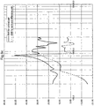
- Figure 5a shows that solving the silent haptics problem gives zero pressure on-axis, but leaves a residual velocity at node 22. Conversely, solving the multi-region (MR) haptics problem gives zero velocity at node 22 but leaves a residual pressure on axis.
- the combined optimised solution of Figure 4b results in a general reduction in velocity when compared to the silent haptics optimisation. Similarly, the combined optimised solution of Figure 4b results in a general reduction in pressure when compared to the dual or multi-region haptics optimisation.
- the improvement in velocity is concentrated at lower frequencies and the improvement in pressure is concentrated at higher frequencies. The balance of these improvements could be altered by changing the scaling factor s(f).
- the effectiveness of the dual-region (MR) effect is measured as a signal to noise ratio (SNR) between node 44 (the signal) and node 22 (the noise).
- SNR signal to noise ratio
- Figure 5b shows the results for quiet haptics optimisation and for combined optimisation.
- the combined optimisation improves the SNR for frequencies below 450 Hz.
- any optimisation including the MR optimisation, is set by the numerical accuracy of the data supplied to the FE program and its own processing. As shown in Figure 5c , with coefficients accurate to 6 decimal places, 120 dB of separation between the nodes 22 and 44 was achieved. Thus, the proposed signals maximise the output at node 44 and minimise the output at node 22.
- Figure 6 shows a variation of the system in Figure 1a with three inputs. The number of inputs exceeds the number of outputs, so there is an exact solution to silent dual region haptics optimisation. In this case, the on-axis pressure is zero and the velocity at node 22 is also zero.
- a third exciter 20 providing a signal RP-3 has been added at a position laterally symmetrical to the second exciter 18.
- Figure 7a shows the scaled sound pressure level against frequency for the signal RP-3 at node 22 and at 10cm on axis.
- the real (solid) and imaginary (dotted) parts of the three input spectra required to solve the silent, multi-region haptics problem are shown in Figure 7b .
- nodal points may allow the non-moving region to extend beyond the point chosen along "nodal lines".
- the direction and shape of the lines are frequency dependent, changing shape at each mode in the system.
- more than one sample point must be used. In this case, the cancellation will not be as complete.
- Figure 8b shows three example sampling points for a nodal line on a touch screen as previously described. Some differentiation between the three points is possible. At low frequencies, the line follows the nodal line at 200Hz of the touch screen of Figure 1a driven by the spectra of Figure 4a .
- the methods described below produces two sets of inputs for the two exciters 16, 18 which result in either the minimum velocity for the three nodes or the maximum velocity for the three nodes. The ratio of these two may be considered as a "signal to noise ratio", with larger values represent a greater degree of success.
- This ratio (SNR) is plotted against frequency in Figure 8c . The result is not as spectacular as that for a single node, but it is a reasonable result.
- the nodal line is steered away from a natural line of symmetry.
- the minimisation of energy functions is a key process in many branches of physical modelling with mathematics, and for example forms the foundation of finite element analysis.
- the task at hand is to determine values of parameters that lead to stationary values to a function (i.e. to find nodal points, lines or pressures).
- the first step of the process is forming the energy function.
- 2
- the stationary values occur at the maximum and the minimum of E.
- E a ⁇ P 1 ⁇ b ⁇ P 2 ⁇ a ⁇ P 1 ⁇ b ⁇ P 2 ⁇
- the silent haptic problem is trivial - a and b are set to equal values. When there is asymmetry in the system, this assumption is no longer valid.
- the problem to solve is to find two sets of input values a and b which give maximum output for audio and minimum output for silent haptics. This is exactly the problem solved in the "variational methods" section.
- P1 and P2 shown in Figure 9a as dB SPL, are the acoustic responses at 10 cm, obtained in this case by finite element simulation - they could equally well have been obtained by measurement.
- the pressure levels result from simulating a DMA with a nominal 1N force plus some frequency dependence. (A typical DMA would have a nominal force of, say, 15 - 30 mN/V. The SPL levels in the figure are thus higher than would be achieved with a real DMA.)
- the method extends similarly to integrals, and to more than two inputs.
- E ⁇ a ⁇ P 1 r _ ⁇ b ⁇ P 2 r _ 2 dA + ⁇ ⁇ a ⁇ ⁇ a + b ⁇ ⁇ b ⁇ 1
- Snm ⁇ Pn r _ ⁇ Pm r _ ⁇ dA
- a P 2 P 1 2 + P 2 2
- b P 1 P 1 2 + P 2 2
- the value of the eigenvalue ⁇ is just the energy associated with that choice of eigenvector.
- n eigenvalues which are found by solving an nth order polynomial equation.
- M _ _ ⁇ v _ ⁇ ⁇ ⁇ v _ 0
- M ⁇ ⁇ I 0
- the final step in choosing the best value for v is to make sure that the real part of the first component is positive (any component could be used for this purpose), i.e.
- a b 1 0.718 ⁇ 0.893 ⁇ j ⁇ 0.682 ⁇ 0.098 ⁇ j
- a b 2 0.623 ⁇ 0.270 ⁇ j ⁇ 0.692 ⁇ 0.244 ⁇ j
- a b 1 + 2 0.719 ⁇ 0.024 ⁇ j ⁇ 0.694 ⁇ 0.025 ⁇ j
- M1 + M2 has a zero eigenvalue.
- M1 + M2 eigenvalues are 0, 0.218 and 0.506: Eigenvector after scaling: (0.434 - 0.011j, -0.418 + 0.199j, 0.764 + 0.115j)
- the "tan theta” method is quicker and simpler to implement, however for three or four inputs the "scaled eigenvector” method is easier. Both methods produce the same result.
- the number of input variables must be greater than the number of measurement points.
- Figure 10a is a block diagram of a parallel solver.
- One error matrix is formed, and the eigenvector corresponding to the lowest eigenvalue is chosen. If m > n, then the eigenvalue will be zero, and the result exact.
- Figure 10b is a block diagram of a recursive solver. An error matrix for the most important output is formed, and the eigenvectors corresponding to the (m-1) lowest eigenvalues are formed. These are used as new input vectors, and the process is repeated. The process ends with a 2 x 2 eigenvalue solution. Backtracking then reassembles the solution to the original problem.
- this process could be turned into an iterative (or sequential) process.
- all the outputs have exact solutions.
- the best linear combination of these solutions is found to minimise the remaining errors.
- M1 + M2 eigenvalues are 0, 0.218 and 0.506: Eigenvector after scaling: (0.434 - 0.011j, -0.418 + 0.199j, 0.764 + 0.115j)
- M1 eigenvalues are 0, 0 and 0.506:
- 0, i.e. exact solution possible M1' eigenvalues, 0 and 0.237 Eigenvector after scaling: (0.608 - 0.145j, 0.772 + 0.114j)
- V1 and V2 to get the inputs 0.608 ⁇ 0.145 j V 1 + 0.772 + 0114
- V 2 0.404 ⁇ 0.095 j , ⁇ 0.352 + 0.268 j , 0.737 ⁇ 0.042 j Normalise and scale the result: (0.434 - 0.011j, -0.418 + 0.199j, 0.764 + 0.115j)
- a.V1 + b.V2 is also an eigenvector corresponding to a zero eigenvalue - i.e. it is an exact solution to the acoustics problem.
- V1 and V2 to get the inputs 0.984 ⁇ 0.016 j V 1 + 0.113 + 0.115 j
- V 2 0.776 ⁇ 0.207 j , 0.473 + 0.283 j , 0.290 ⁇ 0.124 j Normalise and scale the result: (0.755 - 0.211j, -0.466 + 0.270j, 0.246 + 0.104j)
- the two methods are not mutually exclusive, and the parallel method may be adopted at any point in the sequential process, particularly to finish the process.
- the sequential method is useful where the number of inputs does not exceed the number of outputs, particularly when some of the outputs are more important than others. The important outputs are solved exactly, and those remaining get a best fit solution.
Landscapes
- Engineering & Computer Science (AREA)
- General Engineering & Computer Science (AREA)
- Theoretical Computer Science (AREA)
- Physics & Mathematics (AREA)
- Human Computer Interaction (AREA)
- General Physics & Mathematics (AREA)
- Acoustics & Sound (AREA)
- User Interface Of Digital Computer (AREA)
- Position Input By Displaying (AREA)
Claims (8)
- Berührungsempfindliche Vorrichtung, umfassend eine Platte, welche in der Lage ist, Biegewellen zu unterstützen, einen benutzerzugänglichen berührungsempfindlichen Bildschirm (12), der auf oder als Teil einer Fläche der Platte bereitgestellt ist, wobei der berührungsempfindliche Bildschirm (12) eine Mehrzahl von unterschiedlichen Erfassungsbereichen aufweist, eine Mehrzahl von Schwingungserregern (16, 18), welche mit der Platte gekoppelt sind, um die Platte mit Biegewellen zu beaufschlagen, um eine taktile Rückkopplung an die Mehrzahl von Erfassungsbereichen, als Reaktion auf einen Benutzer, der einen Erfassungsbereich berührt, bereitzustellen, und ein Signalverarbeitungsmittel (20), welches ausgebildet ist, um Signale an die Schwingungserreger (16, 18) anzulegen, um Biegewellen zu steuern, welche durch die Mehrzahl von Schwingungserregern (16, 18) auf die Platte aufgebracht werden, dadurch gekennzeichnet, dass
die Steuerung so erfolgt, dass der Erfassungsbereich, der vom Benutzer berührt wird, veranlasst wird, antinodal zu sein, um die Amplitude der aufgebrachten Biegewellen am Erfassungsbereich zu maximieren, welcher von dem Benutzer berührt wird, und jeder andere Erfassungsbereich veranlasst wird, nodal zu sein, um die Amplitude der aufgebrachten Biegewellen an jedem anderen Erfassungsbereich zu reduzieren oder minimieren. - Vorrichtung nach Anspruch 1, wobei die Schwingungserreger (16, 18) um die Platte (12) herum voneinander beabstandet sind.
- Vorrichtung nach Anspruch 1 oder Anspruch 2, wobei die Schwingungserreger (16, 18) an dem Umfang der Platte (12) angeordnet sind.
- Vorrichtung nach einem der vorhergehenden Ansprüche, wobei das Signalverarbeitungsmittel ausgebildet ist, um mindestens eines von dem Zeitablauf, der Phase und der Frequenz des Signals zu steuern, das an jeden Schwingungserreger (16, 18) angelegt wird.
- Vorrichtung nach einem der vorhergehenden Ansprüche, ferner umfassend eine Anzahl n von Erfassungsbereichen und eine Anzahl n+1 von Schwingungserregern (16, 18).
- Vorrichtung nach einem der vorhergehenden Ansprüche, wobei die Platte (12) bewusst resonant ist und wobei die Signale, die an die Schwingungserreger (16, 18) angewendet werden, veranlassen, dass die Platte (12) in Resonanz versetzt wird.
- Vorrichtung nach einem der vorhergehenden Ansprüche, wobei das Signalverarbeitungsmittel Signale an die Schwingungserreger (16, 18) anwendet, sodass gleichzeitig mehrfache vorgesehene haptische Signale an mehreren Stellen bereitgestellt werden, welche berührt werden, während Nebensprechen zwischen den Stellen minimiert wird.
- Verfahren zum Betreiben einer berührungsempfindlichen Vorrichtung (10), wobei die berührungsempfindliche Vorrichtung eine Platte, die in der Lage ist, Biegewellen zu unterstützen, einen benutzerzugänglichen berührungsempfindlichen Bildschirm (12), der auf oder als Teil einer Fläche der Platte bereitgestellt ist, wobei der berührungsempfindliche Bildschirm (12) eine Mehrzahl von unterschiedlichen Erfassungsbereichen aufweist, und eine Mehrzahl von Schwingungserregern (16, 18) umfasst, welche mit der Platte gekoppelt sind, wobei das Verfahren umfasst:die Mehrzahl von Schwingungserregern (16, 18) Biegewellen auf die Platte anwendet, um eine taktile Rückkopplung an die Mehrzahl von Erfassungsbereichen als Reaktion auf einen Benutzer, der einen Erfassungsbereich berührt, bereitzustellen undSteuern der Biegewellen mittels eines Signalverarbeitungsmittels (20), welches Signale an die Schwingungserreger (16, 18) anlegt, dadurch gekennzeichnet, dassdie Steuerung so erfolgt, dass der Erfassungsbereich, der vom Benutzer berührt wird, veranlasst wird, antinodal zu sein, um die Amplitude der aufgebrachten Biegewellen im Erfassungsbereich zu maximieren, welcher von dem Benutzer berührt wird, und jeder andere Erfassungsbereich veranlasst wird, nodal zu sein, um die Amplitude der aufgebrachten Biegewellen an jedem anderen Erfassungsbereich zu reduzieren oder zu minimieren.
Applications Claiming Priority (2)
| Application Number | Priority Date | Filing Date | Title |
|---|---|---|---|
| GB0818117.4A GB2464117B (en) | 2008-10-03 | 2008-10-03 | Touch sensitive device |
| PCT/JP2009/064365 WO2010038552A1 (en) | 2008-10-03 | 2009-08-07 | Touch sensitive device |
Publications (3)
| Publication Number | Publication Date |
|---|---|
| EP2684111A1 EP2684111A1 (de) | 2014-01-15 |
| EP2684111A4 EP2684111A4 (de) | 2016-07-20 |
| EP2684111B1 true EP2684111B1 (de) | 2019-11-20 |
Family
ID=40019999
Family Applications (1)
| Application Number | Title | Priority Date | Filing Date |
|---|---|---|---|
| EP09817589.6A Active EP2684111B1 (de) | 2008-10-03 | 2009-08-07 | Berührungsempfindliche vorrichtung |
Country Status (9)
| Country | Link |
|---|---|
| US (3) | US9041662B2 (de) |
| EP (1) | EP2684111B1 (de) |
| JP (1) | JP4930957B2 (de) |
| KR (1) | KR101281434B1 (de) |
| CN (2) | CN102016770B (de) |
| CA (1) | CA2769928A1 (de) |
| GB (1) | GB2464117B (de) |
| TW (1) | TWI486846B (de) |
| WO (1) | WO2010038552A1 (de) |
Families Citing this family (96)
| Publication number | Priority date | Publication date | Assignee | Title |
|---|---|---|---|---|
| GB2464117B (en) * | 2008-10-03 | 2015-01-28 | Hiwave Technologies Uk Ltd | Touch sensitive device |
| CN101995996B (zh) * | 2010-11-30 | 2012-10-17 | 汉王科技股份有限公司 | 一种触摸屏的机械波定位方法及装置 |
| US11327599B2 (en) | 2011-04-26 | 2022-05-10 | Sentons Inc. | Identifying a contact type |
| US9639213B2 (en) | 2011-04-26 | 2017-05-02 | Sentons Inc. | Using multiple signals to detect touch input |
| US9477350B2 (en) | 2011-04-26 | 2016-10-25 | Sentons Inc. | Method and apparatus for active ultrasonic touch devices |
| US10198097B2 (en) | 2011-04-26 | 2019-02-05 | Sentons Inc. | Detecting touch input force |
| US9189109B2 (en) | 2012-07-18 | 2015-11-17 | Sentons Inc. | Detection of type of object used to provide a touch contact input |
| US10180722B2 (en) * | 2011-05-27 | 2019-01-15 | Honeywell International Inc. | Aircraft user interfaces with multi-mode haptics |
| CN102799300B (zh) * | 2011-05-28 | 2016-07-06 | 宸鸿科技(厦门)有限公司 | 触摸点侦测装置及其侦测方法 |
| EP2754008A4 (de) * | 2011-06-21 | 2015-04-22 | Univ Northwestern | Berührungsschnittstellenvorrichtung und verfahren zum anwenden von querkräften auf menschliche gliedmassen |
| US20130113760A1 (en) * | 2011-11-07 | 2013-05-09 | Google Inc. | Techniques for providing localized tactile feedback to a user via an electro-acoustic touch display of a user device |
| KR102070612B1 (ko) | 2011-11-18 | 2020-01-30 | 센톤스 아이엔씨. | 국소형 햅틱 피드백 |
| US11262253B2 (en) | 2017-08-14 | 2022-03-01 | Sentons Inc. | Touch input detection using a piezoresistive sensor |
| US10235004B1 (en) | 2011-11-18 | 2019-03-19 | Sentons Inc. | Touch input detector with an integrated antenna |
| CN107562281B (zh) | 2011-11-18 | 2020-12-22 | 森顿斯公司 | 检测触摸输入力 |
| GB201200587D0 (en) * | 2012-01-13 | 2012-02-29 | Hiwave Technologies Uk Ltd | Haptic feedback and pressure sensing |
| JP6032657B2 (ja) * | 2012-04-27 | 2016-11-30 | パナソニックIpマネジメント株式会社 | 触感呈示装置、触感呈示方法、駆動信号生成装置および駆動信号生成方法 |
| GB201208853D0 (en) * | 2012-05-18 | 2012-07-04 | Hiwave Technologies Uk Ltd | Panel for use in vibratory panel device |
| GB201208852D0 (en) * | 2012-05-18 | 2012-07-04 | Hiwave Technologies Uk Ltd | Vibratory panel devices and methods for controlling vibratory panel devices |
| GB201208851D0 (en) * | 2012-05-18 | 2012-07-04 | Hiwave Technologies Uk Ltd | Method of designing a panel assembly for a vibratory panel device |
| FR2991791B1 (fr) * | 2012-06-06 | 2014-08-08 | Commissariat Energie Atomique | Interface de stimulation tactile par retournement temporel |
| CZ303999B6 (cs) * | 2012-09-13 | 2013-08-07 | Ceské vysoké ucení technické v Praze - Fakulta elektrotechnická | Bezkontaktní indikátor elektrického výkonu procházejícího prívodní snurou |
| CN103713753B (zh) * | 2012-09-29 | 2017-06-27 | 联想(北京)有限公司 | 一种信息处理的方法及一种电子设备 |
| CN104395866B (zh) * | 2012-11-30 | 2018-02-23 | 松下知识产权经营株式会社 | 触觉提示装置及触觉提示方法 |
| JP5849061B2 (ja) * | 2013-03-28 | 2016-01-27 | 京セラドキュメントソリューションズ株式会社 | 表示入力装置及びこれを備えた画像形成装置 |
| GB2513884B (en) | 2013-05-08 | 2015-06-17 | Univ Bristol | Method and apparatus for producing an acoustic field |
| JP2015028766A (ja) * | 2013-06-24 | 2015-02-12 | パナソニックIpマネジメント株式会社 | 触感呈示装置および触感呈示方法 |
| US9459715B1 (en) | 2013-09-20 | 2016-10-04 | Sentons Inc. | Using spectral control in detecting touch input |
| WO2015059887A1 (ja) | 2013-10-25 | 2015-04-30 | パナソニックIpマネジメント株式会社 | 電子機器 |
| JP2015121983A (ja) * | 2013-12-24 | 2015-07-02 | 京セラ株式会社 | 触感呈示装置 |
| JP2015130168A (ja) * | 2013-12-31 | 2015-07-16 | イマージョン コーポレーションImmersion Corporation | 摩擦拡張制御、及び、タッチコントロールパネルのボタンを摩擦拡張制御部へと変換する方法 |
| US9612658B2 (en) | 2014-01-07 | 2017-04-04 | Ultrahaptics Ip Ltd | Method and apparatus for providing tactile sensations |
| CN115700434A (zh) * | 2014-09-02 | 2023-02-07 | 苹果公司 | 用于可变触觉输出的语义框架 |
| GB2530036A (en) | 2014-09-09 | 2016-03-16 | Ultrahaptics Ltd | Method and apparatus for modulating haptic feedback |
| US20170220223A1 (en) * | 2014-09-16 | 2017-08-03 | Hewlett-Packard Development Company, L.P. | Generate Touch Input Signature for Discrete Cursor Movement |
| CN107534810B (zh) | 2015-02-20 | 2019-12-20 | 超级触觉资讯处理有限公司 | 用于提供改进的触觉反馈的方法 |
| SG11201706557SA (en) | 2015-02-20 | 2017-09-28 | Ultrahaptics Ip Ltd | Perceptions in a haptic system |
| US10845877B2 (en) * | 2015-04-27 | 2020-11-24 | Samsung Electronics Co., Ltd. | Apparatus and method of forming localized vibration field, and method of disposing exciters |
| KR102631306B1 (ko) * | 2015-04-27 | 2024-01-30 | 삼성전자주식회사 | 국소 진동장 형성 장치 및 방법과, 가진기 배치 방법 |
| US10818162B2 (en) | 2015-07-16 | 2020-10-27 | Ultrahaptics Ip Ltd | Calibration techniques in haptic systems |
| US11189140B2 (en) | 2016-01-05 | 2021-11-30 | Ultrahaptics Ip Ltd | Calibration and detection techniques in haptic systems |
| US10129646B2 (en) | 2016-03-28 | 2018-11-13 | Lg Display Co., Ltd. | Panel vibration type sound generating display device |
| KR101704517B1 (ko) | 2016-03-28 | 2017-02-09 | 엘지디스플레이 주식회사 | 패널 진동형 음향 발생 표시 장치 |
| KR102663406B1 (ko) | 2016-04-04 | 2024-05-14 | 엘지디스플레이 주식회사 | 패널 진동형 음향 발생 액츄에이터 및 그를 포함하는 양면 표시 장치 |
| KR20170114471A (ko) | 2016-04-05 | 2017-10-16 | 엘지디스플레이 주식회사 | 유기발광 표시 장치 |
| US10531212B2 (en) | 2016-06-17 | 2020-01-07 | Ultrahaptics Ip Ltd. | Acoustic transducers in haptic systems |
| US10268275B2 (en) | 2016-08-03 | 2019-04-23 | Ultrahaptics Ip Ltd | Three-dimensional perceptions in haptic systems |
| US10755538B2 (en) | 2016-08-09 | 2020-08-25 | Ultrahaptics ilP LTD | Metamaterials and acoustic lenses in haptic systems |
| US11676461B2 (en) * | 2016-08-29 | 2023-06-13 | Sony Corporation | Information processing device, information processing method, and program for controlling haptics based on context information |
| US10123128B2 (en) | 2016-09-07 | 2018-11-06 | Microsoft Technology Licensing, Llc | Speaker arrangement |
| US10908741B2 (en) | 2016-11-10 | 2021-02-02 | Sentons Inc. | Touch input detection along device sidewall |
| US10296144B2 (en) | 2016-12-12 | 2019-05-21 | Sentons Inc. | Touch input detection with shared receivers |
| US10943578B2 (en) | 2016-12-13 | 2021-03-09 | Ultrahaptics Ip Ltd | Driving techniques for phased-array systems |
| US10497358B2 (en) | 2016-12-23 | 2019-12-03 | Ultrahaptics Ip Ltd | Transducer driver |
| FR3061567B1 (fr) * | 2017-01-03 | 2019-05-31 | Hap2U | Interface tactile comportant un capteur de force |
| US10126877B1 (en) | 2017-02-01 | 2018-11-13 | Sentons Inc. | Update of reference data for touch input detection |
| ES2955882T3 (es) | 2017-02-16 | 2023-12-07 | Behr Hella Thermocontrol Gmbh | Unidad de mando para un componente de vehículo, en particular interfaz hombre-máquina para un vehículo |
| US10585522B2 (en) | 2017-02-27 | 2020-03-10 | Sentons Inc. | Detection of non-touch inputs using a signature |
| US10388186B2 (en) | 2017-04-17 | 2019-08-20 | Facebook, Inc. | Cutaneous actuators with dampening layers and end effectors to increase perceptibility of haptic signals |
| GB2561883A (en) * | 2017-04-27 | 2018-10-31 | Cambridge Touch Tech Ltd | Touchscreen panel haptics |
| US11048329B1 (en) | 2017-07-27 | 2021-06-29 | Emerge Now Inc. | Mid-air ultrasonic haptic interface for immersive computing environments |
| US11580829B2 (en) | 2017-08-14 | 2023-02-14 | Sentons Inc. | Dynamic feedback for haptics |
| US10423229B2 (en) * | 2017-08-17 | 2019-09-24 | Google Llc | Adjusting movement of a display screen to compensate for changes in speed of movement across the display screen |
| KR102367747B1 (ko) | 2017-09-29 | 2022-02-25 | 엘지디스플레이 주식회사 | 포스센서를 구비하는 표시장치 및 그의 제조방법 |
| US11531395B2 (en) | 2017-11-26 | 2022-12-20 | Ultrahaptics Ip Ltd | Haptic effects from focused acoustic fields |
| US10356523B2 (en) | 2017-12-13 | 2019-07-16 | Nvf Tech Ltd | Distributed mode loudspeaker actuator including patterned electrodes |
| FR3076017B1 (fr) * | 2017-12-21 | 2020-10-30 | Commissariat Energie Atomique | Dispositif surfacique offrant une deformation localisee amelioree |
| WO2019122762A1 (fr) * | 2017-12-21 | 2019-06-27 | Commissariat A L'energie Atomique Et Aux Energies Alternatives | Dispositif surfacique offrant une deformation localisee amelioree |
| EP3729417B1 (de) | 2017-12-22 | 2025-09-10 | Ultrahaptics Ip Ltd | Verfolgung in haptischen systemen |
| WO2019122916A1 (en) | 2017-12-22 | 2019-06-27 | Ultrahaptics Limited | Minimizing unwanted responses in haptic systems |
| US10477321B2 (en) | 2018-03-05 | 2019-11-12 | Google Llc | Driving distributed mode loudspeaker actuator that includes patterned electrodes |
| SG11202010752VA (en) | 2018-05-02 | 2020-11-27 | Ultrahaptics Ip Ltd | Blocking plate structure for improved acoustic transmission efficiency |
| US11098951B2 (en) | 2018-09-09 | 2021-08-24 | Ultrahaptics Ip Ltd | Ultrasonic-assisted liquid manipulation |
| US11378997B2 (en) | 2018-10-12 | 2022-07-05 | Ultrahaptics Ip Ltd | Variable phase and frequency pulse-width modulation technique |
| WO2020141330A2 (en) | 2019-01-04 | 2020-07-09 | Ultrahaptics Ip Ltd | Mid-air haptic textures |
| US12373033B2 (en) | 2019-01-04 | 2025-07-29 | Ultrahaptics Ip Ltd | Mid-air haptic textures |
| FR3091938B1 (fr) * | 2019-01-22 | 2023-01-20 | Actronika | Procédé de génération de sensations tactiles et interface haptique mettant en œuvre ce procédé |
| KR102743400B1 (ko) * | 2019-03-13 | 2024-12-17 | 베하테체 게엠베하 | 차량용 조작유닛 |
| KR102765540B1 (ko) * | 2019-03-14 | 2025-02-12 | 삼성전자주식회사 | 햅틱 액츄에이터를 포함하는 전자 장치 |
| US11842517B2 (en) | 2019-04-12 | 2023-12-12 | Ultrahaptics Ip Ltd | Using iterative 3D-model fitting for domain adaptation of a hand-pose-estimation neural network |
| FR3095875B1 (fr) * | 2019-05-07 | 2021-06-04 | Commissariat Energie Atomique | Interface tactile offrant un retour vibrotactile a localisation amelioree |
| CN110231869B (zh) * | 2019-06-11 | 2022-08-05 | Oppo广东移动通信有限公司 | 一种触摸电极的控制方法、装置、存储介质及电子设备 |
| CN110570759B (zh) | 2019-08-09 | 2021-02-09 | 华为技术有限公司 | 触控屏、屏幕模组和电子设备 |
| US11374586B2 (en) | 2019-10-13 | 2022-06-28 | Ultraleap Limited | Reducing harmonic distortion by dithering |
| CN114631139A (zh) | 2019-10-13 | 2022-06-14 | 超飞跃有限公司 | 利用虚拟麦克风进行动态封顶 |
| US12231861B2 (en) * | 2019-11-06 | 2025-02-18 | Sony Group Corporation | Signal processing device, signal processing method, and image display device |
| US11169610B2 (en) | 2019-11-08 | 2021-11-09 | Ultraleap Limited | Tracking techniques in haptic systems |
| FR3105491B1 (fr) * | 2019-12-23 | 2023-04-21 | Commissariat Energie Atomique | Dispositif d’interaction haptique ou acoustique à surface vibrante, procédé et programme d’ordinateur correspondants |
| US11715453B2 (en) | 2019-12-25 | 2023-08-01 | Ultraleap Limited | Acoustic transducer structures |
| US11816267B2 (en) | 2020-06-23 | 2023-11-14 | Ultraleap Limited | Features of airborne ultrasonic fields |
| US11886639B2 (en) | 2020-09-17 | 2024-01-30 | Ultraleap Limited | Ultrahapticons |
| CN114442796A (zh) * | 2020-11-05 | 2022-05-06 | 上海艾为电子技术股份有限公司 | 振动装置及其局部振动调整方法、电子设备 |
| JP7351042B2 (ja) | 2021-07-01 | 2023-09-26 | 三菱電機株式会社 | 触覚提示装置及び触覚提示方法 |
| US12517585B2 (en) | 2021-07-15 | 2026-01-06 | Ultraleap Limited | Control point manipulation techniques in haptic systems |
| WO2023119483A1 (ja) | 2021-12-22 | 2023-06-29 | 三菱電機株式会社 | 触覚提示装置、ディスプレイ装置、データ端末装置、および触覚提示方法 |
| WO2026060585A1 (zh) * | 2024-09-19 | 2026-03-26 | 广州视源电子科技股份有限公司 | 触觉反馈方法、装置以及显示设备 |
Citations (1)
| Publication number | Priority date | Publication date | Assignee | Title |
|---|---|---|---|---|
| US20070002029A1 (en) * | 2005-06-30 | 2007-01-04 | Kabushiki Kaisha Toshiba | Information processing device and method of controlling vibration of touch panel |
Family Cites Families (34)
| Publication number | Priority date | Publication date | Assignee | Title |
|---|---|---|---|---|
| US4216352A (en) * | 1978-11-02 | 1980-08-05 | The Charles Stark Draper Laboratory, Inc. | Two coordinate position sensing systems |
| US4885565A (en) | 1988-06-01 | 1989-12-05 | General Motors Corporation | Touchscreen CRT with tactile feedback |
| JP2804937B2 (ja) | 1992-10-15 | 1998-09-30 | 矢崎総業株式会社 | システムスイッチ装置 |
| JPH0713075A (ja) | 1993-06-24 | 1995-01-17 | Nikon Corp | ズームレンズ |
| UA51671C2 (uk) | 1995-09-02 | 2002-12-16 | Нью Транзд'Юсез Лімітед | Акустичний пристрій |
| US5977867A (en) | 1998-05-29 | 1999-11-02 | Nortel Networks Corporation | Touch pad panel with tactile feedback |
| US6429846B2 (en) * | 1998-06-23 | 2002-08-06 | Immersion Corporation | Haptic feedback for touchpads and other touch controls |
| CZ20022173A3 (cs) | 1999-12-23 | 2002-09-11 | New Transducers Limited | Zařízení citlivé na kontakt |
| TW511391B (en) | 2000-01-24 | 2002-11-21 | New Transducers Ltd | Transducer |
| JP3949912B2 (ja) * | 2000-08-08 | 2007-07-25 | 株式会社エヌ・ティ・ティ・ドコモ | 携帯型電子機器、電子機器、振動発生器、振動による報知方法および報知制御方法 |
| US7084854B1 (en) * | 2000-09-28 | 2006-08-01 | Immersion Corporation | Actuator for providing tactile sensations and device for directional tactile sensations |
| GB0031246D0 (en) * | 2000-12-20 | 2001-01-31 | New Transducers Ltd | Vibro-acoustic/human machine interface device |
| US6911901B2 (en) * | 2000-12-20 | 2005-06-28 | New Transducers Limited | Multi-functional vibro-acoustic device |
| GB0116310D0 (en) | 2001-07-04 | 2001-08-29 | New Transducers Ltd | Contact sensitive device |
| US11275405B2 (en) * | 2005-03-04 | 2022-03-15 | Apple Inc. | Multi-functional hand-held device |
| US6871149B2 (en) * | 2002-12-06 | 2005-03-22 | New Transducers Limited | Contact sensitive device |
| GB0228512D0 (en) | 2002-12-06 | 2003-01-15 | New Transducers Ltd | Contact sensitive device |
| US7176902B2 (en) * | 2003-10-10 | 2007-02-13 | 3M Innovative Properties Company | Wake-on-touch for vibration sensing touch input devices |
| JP4478436B2 (ja) * | 2003-11-17 | 2010-06-09 | ソニー株式会社 | 入力装置、情報処理装置、リモートコントロール装置および入力装置の制御方法 |
| US7728819B2 (en) | 2003-11-17 | 2010-06-01 | Sony Corporation | Input device, information processing device, remote control device, and input device control method |
| JP2005258666A (ja) * | 2004-03-10 | 2005-09-22 | Sony Corp | 入力装置および電子機器並びに電子機器の感触フィードバック入力方法 |
| JP2005276089A (ja) * | 2004-03-26 | 2005-10-06 | Seiko Epson Corp | 入力装置、画像表示装置及びプロジェクタ |
| WO2005111968A1 (en) * | 2004-05-13 | 2005-11-24 | Antennahead Pty Ltd | An electronic learning device |
| JP2006048302A (ja) * | 2004-08-03 | 2006-02-16 | Sony Corp | 圧電複合装置、その製造方法、その取扱方法、その制御方法、入出力装置及び電子機器 |
| US20060097996A1 (en) * | 2004-11-10 | 2006-05-11 | Alps Electric Co., Ltd. | Input device |
| US7616192B2 (en) * | 2005-07-28 | 2009-11-10 | Avago Technologies Ecbu Ip (Singapore) Pte. Ltd. | Touch device and method for providing tactile feedback |
| JP2007104567A (ja) * | 2005-10-07 | 2007-04-19 | Sharp Corp | 電子機器 |
| JP5208362B2 (ja) * | 2005-10-28 | 2013-06-12 | ソニー株式会社 | 電子機器 |
| US8780053B2 (en) * | 2007-03-21 | 2014-07-15 | Northwestern University | Vibrating substrate for haptic interface |
| JP2008123429A (ja) * | 2006-11-15 | 2008-05-29 | Sony Corp | タッチパネルディスプレイ装置および電子機器並びに遊技機器 |
| CN101836175B (zh) * | 2007-09-18 | 2013-04-24 | 森赛格公司 | 用于感觉刺激的方法和设备 |
| US10289199B2 (en) * | 2008-09-29 | 2019-05-14 | Apple Inc. | Haptic feedback system |
| GB2464117B (en) * | 2008-10-03 | 2015-01-28 | Hiwave Technologies Uk Ltd | Touch sensitive device |
| JP5788887B2 (ja) * | 2009-10-29 | 2015-10-07 | ニュー トランスデューサーズ リミテッド | タッチセンシティブデバイス |
-
2008
- 2008-10-03 GB GB0818117.4A patent/GB2464117B/en not_active Expired - Fee Related
-
2009
- 2009-08-06 TW TW098126548A patent/TWI486846B/zh not_active IP Right Cessation
- 2009-08-07 EP EP09817589.6A patent/EP2684111B1/de active Active
- 2009-08-07 US US12/921,935 patent/US9041662B2/en active Active
- 2009-08-07 KR KR1020107024486A patent/KR101281434B1/ko not_active Expired - Fee Related
- 2009-08-07 WO PCT/JP2009/064365 patent/WO2010038552A1/en not_active Ceased
- 2009-08-07 CN CN200980116622.8A patent/CN102016770B/zh not_active Expired - Fee Related
- 2009-08-07 JP JP2011517323A patent/JP4930957B2/ja not_active Expired - Fee Related
- 2009-08-07 CN CN201610703499.1A patent/CN106445103B/zh not_active Expired - Fee Related
- 2009-08-07 CA CA2769928A patent/CA2769928A1/en not_active Abandoned
-
2015
- 2015-04-23 US US14/694,823 patent/US20150277565A1/en not_active Abandoned
-
2017
- 2017-06-02 US US15/612,778 patent/US10108268B2/en active Active
Patent Citations (1)
| Publication number | Priority date | Publication date | Assignee | Title |
|---|---|---|---|---|
| US20070002029A1 (en) * | 2005-06-30 | 2007-01-04 | Kabushiki Kaisha Toshiba | Information processing device and method of controlling vibration of touch panel |
Also Published As
| Publication number | Publication date |
|---|---|
| GB0818117D0 (en) | 2008-11-05 |
| CN106445103A (zh) | 2017-02-22 |
| US20170329408A1 (en) | 2017-11-16 |
| US9041662B2 (en) | 2015-05-26 |
| TWI486846B (zh) | 2015-06-01 |
| CN106445103B (zh) | 2019-07-30 |
| GB2464117A (en) | 2010-04-07 |
| EP2684111A4 (de) | 2016-07-20 |
| KR20100121555A (ko) | 2010-11-17 |
| CN102016770B (zh) | 2016-09-21 |
| GB2464117B (en) | 2015-01-28 |
| US20110090167A1 (en) | 2011-04-21 |
| US10108268B2 (en) | 2018-10-23 |
| JP2011527791A (ja) | 2011-11-04 |
| EP2684111A1 (de) | 2014-01-15 |
| TW201020889A (en) | 2010-06-01 |
| JP4930957B2 (ja) | 2012-05-16 |
| KR101281434B1 (ko) | 2013-07-02 |
| WO2010038552A1 (en) | 2010-04-08 |
| US20150277565A1 (en) | 2015-10-01 |
| WO2010038552A8 (en) | 2010-06-10 |
| CN102016770A (zh) | 2011-04-13 |
| CA2769928A1 (en) | 2010-04-08 |
Similar Documents
| Publication | Publication Date | Title |
|---|---|---|
| EP2684111B1 (de) | Berührungsempfindliche vorrichtung | |
| US9159207B2 (en) | Haptic device | |
| US9870094B2 (en) | Touch sensitive device | |
| US10986446B2 (en) | Panel loudspeaker controller and a panel loudspeaker | |
| US20120140945A1 (en) | Audio Apparatus | |
| US10845877B2 (en) | Apparatus and method of forming localized vibration field, and method of disposing exciters | |
| GB2256111A (en) | Distributed sensors for active vibration control | |
| Johnson | Active control of sound transmission | |
| JP6910641B2 (ja) | 小型スピーカの設計支援装置及びスピーカの設計支援方法 | |
| Homaei et al. | Application of the electrostatic micro-speakers for producing audible directional sound | |
| Morales et al. | Comparison of Experiment and Simulation of Ultrasonic Mid-air Haptic Forces | |
| JP7285513B2 (ja) | 音場解析装置、音場解析方法及びプログラム | |
| Landes et al. | Large scale computation of coupled electro-acoustic systems using ANSYS and CAPA | |
| KR102631306B1 (ko) | 국소 진동장 형성 장치 및 방법과, 가진기 배치 방법 | |
| Hansen et al. | Active control of low-frequency sound in a mining vehicle cabin | |
| Kolbrek | Simulation of sound propagation in an axisymmetric duct | |
| Chang | Modeling of acoustic reflection and radiation fields generated from elastic boundary using MHSV model reduction | |
| Lerch et al. | CAE Environment for Electromechanical Microsystems | |
| HK1161648B (en) | Touch sensitive device | |
| HK1161648A (en) | Touch sensitive device |
Legal Events
| Date | Code | Title | Description |
|---|---|---|---|
| PUAI | Public reference made under article 153(3) epc to a published international application that has entered the european phase |
Free format text: ORIGINAL CODE: 0009012 |
|
| 17P | Request for examination filed |
Effective date: 20110826 |
|
| AK | Designated contracting states |
Kind code of ref document: A1 Designated state(s): AT BE BG CH CY CZ DE DK EE ES FI FR GB GR HR HU IE IS IT LI LT LU LV MC MK MT NL NO PL PT RO SE SI SK SM TR |
|
| RAP1 | Party data changed (applicant data changed or rights of an application transferred) |
Owner name: HIWAVE TECHNOLOGIES (UK) LIMITED |
|
| RA4 | Supplementary search report drawn up and despatched (corrected) |
Effective date: 20160621 |
|
| RIC1 | Information provided on ipc code assigned before grant |
Ipc: G06F 3/041 20060101AFI20160615BHEP Ipc: G06F 3/038 20130101ALI20160615BHEP |
|
| RAP1 | Party data changed (applicant data changed or rights of an application transferred) |
Owner name: NVF TECH LTD |
|
| STAA | Information on the status of an ep patent application or granted ep patent |
Free format text: STATUS: EXAMINATION IS IN PROGRESS |
|
| 17Q | First examination report despatched |
Effective date: 20180417 |
|
| GRAP | Despatch of communication of intention to grant a patent |
Free format text: ORIGINAL CODE: EPIDOSNIGR1 |
|
| STAA | Information on the status of an ep patent application or granted ep patent |
Free format text: STATUS: GRANT OF PATENT IS INTENDED |
|
| RIC1 | Information provided on ipc code assigned before grant |
Ipc: G06F 3/038 20130101ALI20190429BHEP Ipc: G06F 3/01 20060101ALI20190429BHEP Ipc: G06F 3/041 20060101AFI20190429BHEP |
|
| INTG | Intention to grant announced |
Effective date: 20190531 |
|
| GRAS | Grant fee paid |
Free format text: ORIGINAL CODE: EPIDOSNIGR3 |
|
| GRAA | (expected) grant |
Free format text: ORIGINAL CODE: 0009210 |
|
| STAA | Information on the status of an ep patent application or granted ep patent |
Free format text: STATUS: THE PATENT HAS BEEN GRANTED |
|
| RBV | Designated contracting states (corrected) |
Designated state(s): AT BE BG CH CY CZ DE DK EE ES FI FR GR HR HU IE IS IT LI LT LU LV MC MK MT NL NO PL PT RO SE SI SK SM TR |
|
| AK | Designated contracting states |
Kind code of ref document: B1 Designated state(s): AT BE BG CH CY CZ DE DK EE ES FI FR GR HR HU IE IS IT LI LT LU LV MC MK MT NL NO PL PT RO SE SI SK SM TR |
|
| REG | Reference to a national code |
Ref country code: CH Ref legal event code: EP |
|
| REG | Reference to a national code |
Ref country code: DE Ref legal event code: R096 Ref document number: 602009060504 Country of ref document: DE |
|
| REG | Reference to a national code |
Ref country code: IE Ref legal event code: FG4D |
|
| REG | Reference to a national code |
Ref country code: AT Ref legal event code: REF Ref document number: 1204917 Country of ref document: AT Kind code of ref document: T Effective date: 20191215 |
|
| RAP2 | Party data changed (patent owner data changed or rights of a patent transferred) |
Owner name: GOOGLE LLC |
|
| REG | Reference to a national code |
Ref country code: NL Ref legal event code: MP Effective date: 20191120 |
|
| REG | Reference to a national code |
Ref country code: LT Ref legal event code: MG4D |
|
| PG25 | Lapsed in a contracting state [announced via postgrant information from national office to epo] |
Ref country code: FI Free format text: LAPSE BECAUSE OF FAILURE TO SUBMIT A TRANSLATION OF THE DESCRIPTION OR TO PAY THE FEE WITHIN THE PRESCRIBED TIME-LIMIT Effective date: 20191120 Ref country code: BG Free format text: LAPSE BECAUSE OF FAILURE TO SUBMIT A TRANSLATION OF THE DESCRIPTION OR TO PAY THE FEE WITHIN THE PRESCRIBED TIME-LIMIT Effective date: 20200220 Ref country code: ES Free format text: LAPSE BECAUSE OF FAILURE TO SUBMIT A TRANSLATION OF THE DESCRIPTION OR TO PAY THE FEE WITHIN THE PRESCRIBED TIME-LIMIT Effective date: 20191120 Ref country code: SE Free format text: LAPSE BECAUSE OF FAILURE TO SUBMIT A TRANSLATION OF THE DESCRIPTION OR TO PAY THE FEE WITHIN THE PRESCRIBED TIME-LIMIT Effective date: 20191120 Ref country code: LV Free format text: LAPSE BECAUSE OF FAILURE TO SUBMIT A TRANSLATION OF THE DESCRIPTION OR TO PAY THE FEE WITHIN THE PRESCRIBED TIME-LIMIT Effective date: 20191120 Ref country code: NL Free format text: LAPSE BECAUSE OF FAILURE TO SUBMIT A TRANSLATION OF THE DESCRIPTION OR TO PAY THE FEE WITHIN THE PRESCRIBED TIME-LIMIT Effective date: 20191120 Ref country code: LT Free format text: LAPSE BECAUSE OF FAILURE TO SUBMIT A TRANSLATION OF THE DESCRIPTION OR TO PAY THE FEE WITHIN THE PRESCRIBED TIME-LIMIT Effective date: 20191120 Ref country code: GR Free format text: LAPSE BECAUSE OF FAILURE TO SUBMIT A TRANSLATION OF THE DESCRIPTION OR TO PAY THE FEE WITHIN THE PRESCRIBED TIME-LIMIT Effective date: 20200221 Ref country code: NO Free format text: LAPSE BECAUSE OF FAILURE TO SUBMIT A TRANSLATION OF THE DESCRIPTION OR TO PAY THE FEE WITHIN THE PRESCRIBED TIME-LIMIT Effective date: 20200220 |
|
| PG25 | Lapsed in a contracting state [announced via postgrant information from national office to epo] |
Ref country code: IS Free format text: LAPSE BECAUSE OF FAILURE TO SUBMIT A TRANSLATION OF THE DESCRIPTION OR TO PAY THE FEE WITHIN THE PRESCRIBED TIME-LIMIT Effective date: 20200320 Ref country code: HR Free format text: LAPSE BECAUSE OF FAILURE TO SUBMIT A TRANSLATION OF THE DESCRIPTION OR TO PAY THE FEE WITHIN THE PRESCRIBED TIME-LIMIT Effective date: 20191120 |
|
| PG25 | Lapsed in a contracting state [announced via postgrant information from national office to epo] |
Ref country code: RO Free format text: LAPSE BECAUSE OF FAILURE TO SUBMIT A TRANSLATION OF THE DESCRIPTION OR TO PAY THE FEE WITHIN THE PRESCRIBED TIME-LIMIT Effective date: 20191120 Ref country code: CZ Free format text: LAPSE BECAUSE OF FAILURE TO SUBMIT A TRANSLATION OF THE DESCRIPTION OR TO PAY THE FEE WITHIN THE PRESCRIBED TIME-LIMIT Effective date: 20191120 Ref country code: PT Free format text: LAPSE BECAUSE OF FAILURE TO SUBMIT A TRANSLATION OF THE DESCRIPTION OR TO PAY THE FEE WITHIN THE PRESCRIBED TIME-LIMIT Effective date: 20200412 Ref country code: EE Free format text: LAPSE BECAUSE OF FAILURE TO SUBMIT A TRANSLATION OF THE DESCRIPTION OR TO PAY THE FEE WITHIN THE PRESCRIBED TIME-LIMIT Effective date: 20191120 Ref country code: DK Free format text: LAPSE BECAUSE OF FAILURE TO SUBMIT A TRANSLATION OF THE DESCRIPTION OR TO PAY THE FEE WITHIN THE PRESCRIBED TIME-LIMIT Effective date: 20191120 |
|
| REG | Reference to a national code |
Ref country code: AT Ref legal event code: MK05 Ref document number: 1204917 Country of ref document: AT Kind code of ref document: T Effective date: 20191120 |
|
| REG | Reference to a national code |
Ref country code: DE Ref legal event code: R097 Ref document number: 602009060504 Country of ref document: DE |
|
| PG25 | Lapsed in a contracting state [announced via postgrant information from national office to epo] |
Ref country code: SK Free format text: LAPSE BECAUSE OF FAILURE TO SUBMIT A TRANSLATION OF THE DESCRIPTION OR TO PAY THE FEE WITHIN THE PRESCRIBED TIME-LIMIT Effective date: 20191120 Ref country code: SM Free format text: LAPSE BECAUSE OF FAILURE TO SUBMIT A TRANSLATION OF THE DESCRIPTION OR TO PAY THE FEE WITHIN THE PRESCRIBED TIME-LIMIT Effective date: 20191120 |
|
| PLBE | No opposition filed within time limit |
Free format text: ORIGINAL CODE: 0009261 |
|
| STAA | Information on the status of an ep patent application or granted ep patent |
Free format text: STATUS: NO OPPOSITION FILED WITHIN TIME LIMIT |
|
| 26N | No opposition filed |
Effective date: 20200821 |
|
| PG25 | Lapsed in a contracting state [announced via postgrant information from national office to epo] |
Ref country code: AT Free format text: LAPSE BECAUSE OF FAILURE TO SUBMIT A TRANSLATION OF THE DESCRIPTION OR TO PAY THE FEE WITHIN THE PRESCRIBED TIME-LIMIT Effective date: 20191120 Ref country code: PL Free format text: LAPSE BECAUSE OF FAILURE TO SUBMIT A TRANSLATION OF THE DESCRIPTION OR TO PAY THE FEE WITHIN THE PRESCRIBED TIME-LIMIT Effective date: 20191120 Ref country code: SI Free format text: LAPSE BECAUSE OF FAILURE TO SUBMIT A TRANSLATION OF THE DESCRIPTION OR TO PAY THE FEE WITHIN THE PRESCRIBED TIME-LIMIT Effective date: 20191120 |
|
| PG25 | Lapsed in a contracting state [announced via postgrant information from national office to epo] |
Ref country code: IT Free format text: LAPSE BECAUSE OF FAILURE TO SUBMIT A TRANSLATION OF THE DESCRIPTION OR TO PAY THE FEE WITHIN THE PRESCRIBED TIME-LIMIT Effective date: 20191120 |
|
| PG25 | Lapsed in a contracting state [announced via postgrant information from national office to epo] |
Ref country code: MC Free format text: LAPSE BECAUSE OF FAILURE TO SUBMIT A TRANSLATION OF THE DESCRIPTION OR TO PAY THE FEE WITHIN THE PRESCRIBED TIME-LIMIT Effective date: 20191120 |
|
| REG | Reference to a national code |
Ref country code: CH Ref legal event code: PL |
|
| PG25 | Lapsed in a contracting state [announced via postgrant information from national office to epo] |
Ref country code: LI Free format text: LAPSE BECAUSE OF NON-PAYMENT OF DUE FEES Effective date: 20200831 Ref country code: CH Free format text: LAPSE BECAUSE OF NON-PAYMENT OF DUE FEES Effective date: 20200831 Ref country code: LU Free format text: LAPSE BECAUSE OF NON-PAYMENT OF DUE FEES Effective date: 20200807 |
|
| REG | Reference to a national code |
Ref country code: BE Ref legal event code: MM Effective date: 20200831 |
|
| PG25 | Lapsed in a contracting state [announced via postgrant information from national office to epo] |
Ref country code: FR Free format text: LAPSE BECAUSE OF NON-PAYMENT OF DUE FEES Effective date: 20200831 |
|
| PG25 | Lapsed in a contracting state [announced via postgrant information from national office to epo] |
Ref country code: BE Free format text: LAPSE BECAUSE OF NON-PAYMENT OF DUE FEES Effective date: 20200831 Ref country code: IE Free format text: LAPSE BECAUSE OF NON-PAYMENT OF DUE FEES Effective date: 20200807 |
|
| PG25 | Lapsed in a contracting state [announced via postgrant information from national office to epo] |
Ref country code: TR Free format text: LAPSE BECAUSE OF FAILURE TO SUBMIT A TRANSLATION OF THE DESCRIPTION OR TO PAY THE FEE WITHIN THE PRESCRIBED TIME-LIMIT Effective date: 20191120 Ref country code: MT Free format text: LAPSE BECAUSE OF FAILURE TO SUBMIT A TRANSLATION OF THE DESCRIPTION OR TO PAY THE FEE WITHIN THE PRESCRIBED TIME-LIMIT Effective date: 20191120 Ref country code: CY Free format text: LAPSE BECAUSE OF FAILURE TO SUBMIT A TRANSLATION OF THE DESCRIPTION OR TO PAY THE FEE WITHIN THE PRESCRIBED TIME-LIMIT Effective date: 20191120 |
|
| PG25 | Lapsed in a contracting state [announced via postgrant information from national office to epo] |
Ref country code: MK Free format text: LAPSE BECAUSE OF FAILURE TO SUBMIT A TRANSLATION OF THE DESCRIPTION OR TO PAY THE FEE WITHIN THE PRESCRIBED TIME-LIMIT Effective date: 20191120 |
|
| P01 | Opt-out of the competence of the unified patent court (upc) registered |
Effective date: 20230505 |
|
| PGFP | Annual fee paid to national office [announced via postgrant information from national office to epo] |
Ref country code: DE Payment date: 20230829 Year of fee payment: 15 |
|
| REG | Reference to a national code |
Ref country code: DE Ref legal event code: R119 Ref document number: 602009060504 Country of ref document: DE |
|
| PG25 | Lapsed in a contracting state [announced via postgrant information from national office to epo] |
Ref country code: DE Free format text: LAPSE BECAUSE OF NON-PAYMENT OF DUE FEES Effective date: 20250301 |