EP2684536A2 - Dispositif et procédé de vérification d'un gabarit de perçage - Google Patents
Dispositif et procédé de vérification d'un gabarit de perçage Download PDFInfo
- Publication number
- EP2684536A2 EP2684536A2 EP13179734.2A EP13179734A EP2684536A2 EP 2684536 A2 EP2684536 A2 EP 2684536A2 EP 13179734 A EP13179734 A EP 13179734A EP 2684536 A2 EP2684536 A2 EP 2684536A2
- Authority
- EP
- European Patent Office
- Prior art keywords
- plate
- pin
- drilling template
- read
- markings
- Prior art date
- Legal status (The legal status is an assumption and is not a legal conclusion. Google has not performed a legal analysis and makes no representation as to the accuracy of the status listed.)
- Granted
Links
Images


Classifications
-
- A—HUMAN NECESSITIES
- A61—MEDICAL OR VETERINARY SCIENCE; HYGIENE
- A61C—DENTISTRY; APPARATUS OR METHODS FOR ORAL OR DENTAL HYGIENE
- A61C1/00—Dental machines for boring or cutting ; General features of dental machines or apparatus, e.g. hand-piece design
- A61C1/08—Machine parts specially adapted for dentistry
- A61C1/082—Positioning or guiding, e.g. of drills
- A61C1/084—Positioning or guiding, e.g. of drills of implanting tools
-
- A—HUMAN NECESSITIES
- A61—MEDICAL OR VETERINARY SCIENCE; HYGIENE
- A61C—DENTISTRY; APPARATUS OR METHODS FOR ORAL OR DENTAL HYGIENE
- A61C8/00—Means to be fixed to the jaw-bone for consolidating natural teeth or for fixing dental prostheses thereon; Dental implants; Implanting tools
- A61C8/0089—Implanting tools or instruments
-
- Y—GENERAL TAGGING OF NEW TECHNOLOGICAL DEVELOPMENTS; GENERAL TAGGING OF CROSS-SECTIONAL TECHNOLOGIES SPANNING OVER SEVERAL SECTIONS OF THE IPC; TECHNICAL SUBJECTS COVERED BY FORMER USPC CROSS-REFERENCE ART COLLECTIONS [XRACs] AND DIGESTS
- Y10—TECHNICAL SUBJECTS COVERED BY FORMER USPC
- Y10T—TECHNICAL SUBJECTS COVERED BY FORMER US CLASSIFICATION
- Y10T29/00—Metal working
- Y10T29/49—Method of mechanical manufacture
- Y10T29/49567—Dental appliance making
Definitions
- the invention relates to a device for checking a surgical template, wherein the surgical template has at least one guide channel.
- a drilling template with a guide sleeve for guiding an oral surgical drill is disclosed.
- the drill can also be used in minimal space in the guide sleeve, if this has in its peripheral surface with respect to the sleeve length axis oblique slot.
- Such a guide sleeve also allows a nearly optimal guidance of the drill in the direction of the planned drilling axis.
- the guide sleeve can be anchored via fastening means in the drilling template.
- the fastening means may be formed as part of a change mechanism by means of which the sleeve can be releasably secured to a holder.
- the interchangeable mechanism may comprise a conical element and an associated support, which can be positively connected.
- the manual " Production and application of an individual drilling template "by Straumann GmbH discloses a manufacturing method of a drilling template.
- a first Step is a situation model made of plaster.
- a plastic splint is deep-drawn onto the situation model.
- a second plaster model is produced, sawed at the planned implant position, the measured bone profile transmitted and an implant axis determined.
- a wax-up of the planned restoration is made on the original situation model.
- a duplicate of the wax-up model is produced and a plastic rail is deep-drawn on it.
- the new plastic splint is transferred to the situation model.
- a seventh step the determined implant position and implant axis are marked on the situation model and the bore is performed by means of a parallelometer with a pilot drill.
- a titanium pin is inserted into the hole.
- a new plastic rail is deep-drawn over the titanium pin inserted in the model.
- the plastic rail is removed from the model and the titanium pin is replaced by a shorter titanium pin.
- the plastic splint is placed on the previously made model with the bone profile drawn in and the implant axis is checked. If necessary, the position and direction of the hole can still be corrected.
- a titanium pin with a gradation is inserted into the hole and any possible undercuts blocked with plaster, wax or plastic.
- a new plastic rail is deep-drawn via the titanium pin with gradation.
- an occlusal opening is cut or ground into the plastic splint and a drill sleeve with an edge is inserted into the plastic splint.
- the plastic rail ground or cut in the area of the implantation site.
- a drill sleeve can be slipped over the titanium pin and this drill sleeve can be fixed with plastic or plaster.
- a plastic rail is deep-drawn over the drill sleeve and the drill hole ground free for receiving the pilot drill.
- DE 199 52 962 A1 discloses a method of constructing a dental implant drilling aid by first performing an X-ray of the jaw, followed by a three-dimensional optical measurement of the visible surface of the jaw and teeth.
- the measurement data sets from the X-ray image and the three-dimensional optical image are correlated with each other.
- a template is planned and generated, which rests on the adjacent teeth and thereby the exact hole of the implant guide hole is made possible.
- the implant Based on the X-ray data, the implant can be determined and positioned in a known manner.
- an implant aid in the form of a drilling template can be ground by means of a CAD / CAM unit.
- a CAD / CAM machine is able to produce the drilling template with the negative of the occlusal surfaces and a guide run for the drill.
- a stop is transmitted, which determines the drilling depth.
- WO 99/32045 A1 discloses a method of making a dental drilling aid for implants. First, a three-dimensional computer image is modeled using a jaw image with respect to an impression surface. After that the location and depth of the drilled holes are determined and a set of implant borehole coordinates are fed to a computerized manufacturing machine. Using a precision tool, a drill guide socket is prepared in the drill body for each of the previously fed well coordinate sets with a well position and well orientation determined from the jaw section.
- a drilling template and a method for producing this drilling template is known, wherein the drilling template has at least one through hole for the passage of the drill into which at least one first guide sleeve can be inserted.
- the guide sleeve has, in a lower region, an outer diameter which substantially corresponds to the inner diameter of the through-hole. In an upper region, the guide sleeve has a larger outer diameter, so that the upper portion is supported on the surrounding the through hole edge of the drilling template.
- a method and a device for checking a drilling template is known, wherein a contact point of the measuring pin is drawn on a measuring template spaced apart from the drilling template by means of a measuring pin inserted into the drilling sleeve.
- a disadvantage of these methods is that most CAD / CAM machines are limited in their degrees of freedom and, in particular, windings that are not skewed to one another are not feasible. Therefore, the production of surgical guides using a CAD / CAM machine is only possible for a limited range of indications.
- the drilling template is produced either individually in the laboratory or after prior CAD / CAM planning central, for example, using a hexapod whose construction allows for movement of the object to be machined in all six degrees of freedom, and by means of a parallelometer for performing vertical bores.
- CT-DVT stencils, bite plates and jaw models made of gypsum are usually used for central production. These are mounted on the intricately designed Hexapod and adjusted with the aid of several measuring points. This process is very complicated and therefore error-prone.
- the object of this invention is therefore to provide a method which allows the production of any drilling template in particular with skewed drilling axes using a conventional manufacturing machine with limited degrees of freedom.
- An object of the invention is a device for checking a manufactured surgical template.
- the drilling template has at least one guide channel.
- the device has at least one pin and a plate, wherein the pin can be inserted into the guide channel.
- the plate is disposed at an adjustable distance above the drilling template and markings are provided on the plate for reading a position.
- the pin, the plate and the drilling template to be tested are designed and arranged in such a way that the pin points to a position on the plate, which can be read by means of the markings on the plate.
- the plate is made of a semi-transparent material.
- the stylus may include a laser aligned along an axis of the stylus that projects a spot of light onto the disc such that when the stylus is in the guide channel is inserted the laser of the pen points to a position on the plate, which can be read by means of the markings on the plate.
- the plate Due to the semi-transparent plate and the laser, the plate need not be brought into contact with the upper tip of the pen to read the position. As a result, the distance between the plate and the drilling template can be set arbitrarily.
- this method Compared with a known validation method, in which pins are inserted into pilot holes of a surgical template and then checked to see if the lower ends of the pins match marks on a printed control sheet, this method has the advantage that a printout of a control sheet is not required.
- this device allows for a more precise inspection of the position and inclination of the guide channel, as in a check with a control sheet, the drilling template is placed on the control sheet, so that the distances between the guide holes and the control sheet are too small to Determine deviations of the inclination and the position of the guide holes reliable.
- the pins can be designed in their dimensions so long that the distance between the drilling template and the plate is large enough to ensure a reliable measurement of the inclination and the position of the guide channels.
- the plate may be a glass plate which can be arranged at a certain distance from the drilling template so that it touches an upper tip of the pin, wherein the position of the upper tip of the pen can be read using the markings on the plate.
- the prepared surgical template may have a guide channel or a plurality of guide channels for a plurality of implant bores.
- a plug-in sleeve is positioned on the base part and firmly glued to it. The coordinates of the position of the pin on the plate can be read and from this the exact inclination and position of the respective guide channel can be determined.
- the markings on the plate can represent a coordinate system with an x-axis and a y-axis.
- the device may have a support which is designed to fit a support region of the surgical template, wherein the positional relationship between the support region of the surgical template and the guide channel and between the support and the plate is known.
- the device may comprise a magnifying glass, which is arranged above the plate and serves to read the markings on the plate.
- the mark on the plate can be enlarged to ensure better readability.
- the upper tip of the pin may be tapered to uniquely determine the position of the upper tip on the plate.
- the lower end of the pen can be designed as desired.
- the pin can be cylindrical, wherein when the pin is inserted into the guide channel a lower end of the pin touches a base plate of the device.
- the inclination and location of the guide channel can be calculated from the length of the pin, the distance between the base plate and the plate, and the coordinates of the upper tip of the pin.
- the pin in the middle region have a conical bearing part, which flies in the inserted state on the drilling template.
- the lower end of the pin does not contact the base plate of the device.
- the pin is in the inserted state with the support member on the inserted sleeve.
- the position and the inclination of the guide channel can be calculated, for example, by means of a design software based on the known distance between the support member and the upper tip of the pen and on the basis of the coordinates of the upper tip on the plate.
- an expected penetration depth of the drill can be checked, wherein the lower part of the pin is dimensioned such that the distance between the lower tip of the pin and the bearing part corresponds to the penetration depth of the drill.
- Another object of the invention is a method for checking a drilling template using the above-mentioned device.
- the surgical template to be tested is positioned in a known positional relationship with the device, the pin being inserted into the guide channel.
- the plate at a certain distance to the drilling template is arranged, wherein a position on the plate, on which the pin points, is read using the markers.
- the present method has the advantage that no control sheet must be printed and the inclination and the position of the guide channel can be determined more precisely. This determines the exact coordinates of the position on the plate. This will position the drilling template in position relative to the verification device.
- the plate may be positioned at a certain distance from the surgical template so as to contact an upper tip of the stylus, reading the position of the upper tip of the stylus using the markings on the plate.
- the position of the pen tip on the disc can be determined in a simple manner.
- the orientation and position of the guide channel can be checked.
- the orientation and position of the guide channel can be checked in a simple manner.
- nominal values for the coordinates of the upper tip of the stylus on the plate and for the height of the plate can be calculated, and then comparing the desired values with the read actual values.
- the calculation of the target values is computer-aided, taking into account the planned guide bores automatically.
- the read actual values can therefore be compared in a simple manner with the calculated target values.
- the read actual values can be entered into an input mask of the design software and afterwards the actual deviation of the inclination and the position of the guide channel is calculated.
- the plate can be made of a partially transparent material.
- the stylus may include a laser aligned along an axis of the stylus that projects a spot of light onto the disc, the laser of the inserted stylus pointing to a position on the disc read by the markers on the disc.
- the position to which the pin points can be determined in a simple manner by means of the laser.
- the plate can be arranged at any distance from the drilling template.
- the orientation and position of the guide channel can be checked.
- the markings on the plate may represent a coordinate cross with an x-axis and a y-axis, wherein an x-coordinate and a y-coordinate of the position of the upper tip are read by a user.
- the drilling template can be placed with a contact area of the drilling template on a suitably shaped support of the device.
- the drilling template can be precisely positioned relative to the device in a particular positional relationship.
- the drilling template can have a magnifying glass, wherein the markings on the plate can be read by the user by means of the magnifying glass.
- the markings on the plate can be displayed enlarged for better readability.
- the Fig. 1 shows a sketch of a drilling template 1 comprising a base part 2 and a first sleeve 3, a second sleeve 4 and a third sleeve 5 for performing a first implant bore 6 of a second implant bore 7 and a third implant bore 8.
- a first surface 9 of the base part 2 has a Impression 10 of a preparation site.
- the surgical template includes the impression 10 of the entire lower jaw of a patient.
- the drilling template 1 can also be made only for a part of the jaw or merely support points for supporting on the adjacent teeth 11, 12, 13 and 14.
- a second surface 15 of the base part 2 has a first support surface 16, a second support surface 17 and a third Support surface 18 on.
- the base part 2 also has a first through-opening 19, a second through-opening 20 and a third through-opening 21 expanded from the second surface 15 to the first surface 9.
- the sleeves 3, 4 and 5 are inserted into the through holes 19, 20 and 21 with a cylindrical sleeve part and lie with a disc-shaped sleeve part on the bearing surfaces 16, 17 and 18, so that the position and orientation of the sleeves 3, 4 and 5 is determined by the tilting and the position of the bearing surfaces 16, 17 and 18 and by the position of the through holes 19, 20 and 21.
- the sleeves 3, 4 and 5 are firmly bonded to the bearing surfaces 16, 17 and 18.
- the flared through holes 19, 20 and 21 are cone-shaped.
- the Fig. 2 shows a sketch of a section of the drilling template 1 from Fig. 1 comprising the base part 2 and the sleeve 3.
- the first surface 9 of the base part 2 has the impression 10, the second opposing surface 15 of the base part 2 having the first bearing surface 16.
- the sleeve 3 has a first disk-shaped part 30, which rests with a support region 31 on the support surface 16, and a second cylindrical sleeve part 32 which is inserted into the first expanded passage opening 19.
- the sleeve 3 has a guide channel 33, which is intended to guide a drill to perform the implant bore 6 in the jaw 34 of a patient.
- the base part 2 has a stop 35 in the form of a step with a right angle, which fixes the first disc-shaped sleeve member 30 in the lateral direction.
- the stop 35 may be formed as a counterpart to the disk-shaped sleeve part 30.
- the stop may also be formed as a straight plane with one or more stop points on the sleeve.
- the widened passage opening 19 has an outer surface 36, which has an opening angle 38 to an axis 37 of the sleeve 3 and thus of the implant bore 6, which is 20 ° in the present case.
- the first through opening 19 is conical and has a first radius 39 on the first surface 9 and a second radius 40 on the second surface 15 of the base part 2.
- the passage opening 19 is ground out by means of a CAM processing machine such that the second radius 40 corresponds as far as possible to the radius of the second cylindrical sleeve part 32.
- the sleeve is in the inserted state by the Through hole 19, the stop 35 and fixed by the support surface 16 in its position and orientation.
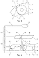
- the Fig. 3 shows a sketch of a section of the drilling template 1 from Fig. 1 and Fig. 2 in the plan view.
- the disc-shaped first sleeve part 30 of the sleeve 3 has the cylindrical guide channel 33.
- the disk-shaped sleeve part 30 rests on the bearing surface 16, which is formed as an inclined plane.
- As stop 35 serve two straight planes 41 and 42 with a first stop point 43 and a second stop point 44th
- the Fig. 4 shows a sketch of a device 50 for checking the drilling template 1 from Fig. 1 and Fig. 2 comprising the base part 2 and the sleeve 3 with the guide channel 33.
- the device 50 has a pin 51, a glass plate 52 and a magnifying glass 53.
- the glass plate 52 is fixed to a holder 54 which is connected to a base plate 55.
- a distance 56 between the glass plate 52 and the base plate 55 is adjustable and can be read using the measuring scale 57.
- the glass plate 52 has a coordinate cross 58 with an x-axis 59 and a y-axis 60, so that the exact position of an upper tip 61 of the pin 51 on the glass plate 52 can be read.
- the device has a support 62, which is designed in the form of a gradation between the base plate 55 and the holder 54.
- a support region 63 is provided which corresponds in its shape to the support 62.
- the drilling template 1 rests on a second support 64.
- the loupe 53 is attached to the bracket 54 via an adjusting means 65 so that the loupe can be adjusted in position to view the position of the upper tip 61 of the pin 51 enlarged.
- the procedure for checking the drilling template 1 runs in several process steps. In the first method, the pin 51 is inserted into the sleeve 3, wherein a lower tip 66 of the pin 51 contacts the base plate 55.
- the distance 56 of the glass plate 52 is adjusted so that the upper tip 61 contacts the glass plate 52.
- the coordinates of the position of the upper peak 61 are read using the x-axis 59 and y-axis 60.
- the inclination and the position of the guide channel 33 of the sleeve 3 are calculated on the basis of the read coordinates and the distance 56. The measured actual values can then be compared with nominal values which were calculated by means of a design software.
- the Fig. 5 shows a sketch of an alternative embodiment of the verification device.
- the difference to the device after Fig. 4 consists in that the pin 51 has a conical bearing part 70 in the central region, which rests on the sleeve 3 in the inserted state.
- the length 71 of the upper part between the upper tip 61 and the support part 70 is known and used together with the coordinates of the position of the upper tip on the glass plate 51 for calculating the inclination and the position of the guide channel 33.
- FIG. 12 shows a sketch of a three-axis machining CAM machine 80 including a first milling tool 81 and a second milling tool 82 controlled by a computer 84 from a blank 83, the above-mentioned drilling template 1 Fig.1 to Fig. 5 grind out, which is painted.
- the computer 84 has input devices, such as a keyboard 85 and a mouse 86, which enables operation of CAD software for inventory planning.
- the computer 84 is connected to a monitor 87 connected, which displays a virtual model 88 of the planned drilling template 1.
- the processing machine 80 may also have four processing axes. According to the present inventive method, the processing machine 80 can be used with limited degrees of freedom for the production of any drilling template even with skewed guide channels. Conventional methods often require the use of a processing machine with at least five processing axes.
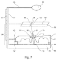
- the Fig. 7 shows a sketch of a device 50 from Fig. 4 alternative device for checking the drilling template 1 from Fig. 1 and Fig. 2 .
- the difference to the device 50 from Fig. 4 consists in that the plate 52 is made of a partially transparent material and that the pin 51 has a laser 90 aligned along an axis of the pen, which emits a laser beam 91 projects a light spot 92 onto the plate 52, the laser of the inserted pin 51 to a position 91 on the plate 52, which is read by means of the coordinate axes 59, 60 on the plate 52.
- the orientation and position of the guide channel 33 are determined and checked.
Landscapes
- Health & Medical Sciences (AREA)
- Oral & Maxillofacial Surgery (AREA)
- General Health & Medical Sciences (AREA)
- Epidemiology (AREA)
- Life Sciences & Earth Sciences (AREA)
- Animal Behavior & Ethology (AREA)
- Dentistry (AREA)
- Public Health (AREA)
- Veterinary Medicine (AREA)
- Orthopedic Medicine & Surgery (AREA)
- Dental Prosthetics (AREA)
- Dental Tools And Instruments Or Auxiliary Dental Instruments (AREA)
- Perforating, Stamping-Out Or Severing By Means Other Than Cutting (AREA)
- Drilling And Boring (AREA)
Applications Claiming Priority (2)
| Application Number | Priority Date | Filing Date | Title |
|---|---|---|---|
| DE102011003557A DE102011003557B9 (de) | 2011-02-03 | 2011-02-03 | Bohrschablone für ein dentales Implantat, ein Verfahren zur Herstellung dieser Bohrschablone sowie eine Vorrichtung zur Überprüfung der Bohrschablone und deren Verwendung |
| EP12706211.5A EP2670337B1 (fr) | 2011-02-03 | 2012-02-02 | Gabarit de forage pour implant dentaire et procédé de production de ce gabarit de forage |
Related Parent Applications (2)
| Application Number | Title | Priority Date | Filing Date |
|---|---|---|---|
| EP12706211.5A Division-Into EP2670337B1 (fr) | 2011-02-03 | 2012-02-02 | Gabarit de forage pour implant dentaire et procédé de production de ce gabarit de forage |
| EP12706211.5A Division EP2670337B1 (fr) | 2011-02-03 | 2012-02-02 | Gabarit de forage pour implant dentaire et procédé de production de ce gabarit de forage |
Publications (3)
| Publication Number | Publication Date |
|---|---|
| EP2684536A2 true EP2684536A2 (fr) | 2014-01-15 |
| EP2684536A3 EP2684536A3 (fr) | 2014-01-22 |
| EP2684536B1 EP2684536B1 (fr) | 2017-05-17 |
Family
ID=45771786
Family Applications (2)
| Application Number | Title | Priority Date | Filing Date |
|---|---|---|---|
| EP13179734.2A Active EP2684536B1 (fr) | 2011-02-03 | 2012-02-02 | Dispositif et procédé de vérification d'un gabarit de perçage |
| EP12706211.5A Active EP2670337B1 (fr) | 2011-02-03 | 2012-02-02 | Gabarit de forage pour implant dentaire et procédé de production de ce gabarit de forage |
Family Applications After (1)
| Application Number | Title | Priority Date | Filing Date |
|---|---|---|---|
| EP12706211.5A Active EP2670337B1 (fr) | 2011-02-03 | 2012-02-02 | Gabarit de forage pour implant dentaire et procédé de production de ce gabarit de forage |
Country Status (5)
| Country | Link |
|---|---|
| US (1) | US9949807B2 (fr) |
| EP (2) | EP2684536B1 (fr) |
| JP (1) | JP5970478B2 (fr) |
| DE (1) | DE102011003557B9 (fr) |
| WO (1) | WO2012104361A2 (fr) |
Families Citing this family (18)
| Publication number | Priority date | Publication date | Assignee | Title |
|---|---|---|---|---|
| EP2739240B1 (fr) | 2011-05-26 | 2020-07-15 | Viax Dental Technologies, Llc | Outil dentaire et dispositifs de guidage |
| DE102011083439B4 (de) * | 2011-09-26 | 2017-06-29 | Sirona Dental Systems Gmbh | Verfahren zur Überprüfung einer Bohrschablone zur Herstellung eines implantatgestützten Zahnersatzes |
| HUE026225T2 (en) * | 2012-03-26 | 2016-06-28 | Konrad Hofmann | Occlusion track layout |
| US9283055B2 (en) | 2014-04-01 | 2016-03-15 | FPJ Enterprises, LLC | Method for establishing drill trajectory for dental implants |
| WO2016036500A1 (fr) * | 2014-09-05 | 2016-03-10 | FPJ Enterprises, LLC | Système pour établir une trajectoire de perçage pour des implants dentaires |
| US9962234B2 (en) | 2014-12-24 | 2018-05-08 | Isethco Llc | Disposable surgical intervention guides, methods, and kits |
| US10136968B2 (en) | 2014-12-24 | 2018-11-27 | Isethco Llc | Disposable surgical intervention guides, methods, and kits |
| DE102016004641A1 (de) * | 2016-04-20 | 2017-10-26 | Axel Scheffer | Verfahren und System zur Erfassung der Ausrichtung von wenigstens einer Bohrhülse in einer für die lagerichtige Implantation von Zahnimplantaten hergestellten Bohrschablone |
| US11007035B2 (en) | 2017-03-16 | 2021-05-18 | Viax Dental Technologies Llc | System for preparing teeth for the placement of veneers |
| US20210386511A1 (en) * | 2018-10-23 | 2021-12-16 | Dentlytec G.P.L. Ltd. | Method and apparatus for dental surgical guide verification |
| EP4175588A4 (fr) | 2020-07-06 | 2024-10-16 | Perfect Fit Crowns, LLC | Procédé et appareil pour restaurations de couronnes dentaires à l'aide de paires manchon-couronne préfabriquées |
| WO2022060017A1 (fr) * | 2020-09-18 | 2022-03-24 | 연세대학교 산학협력단 | Dispositif et procédé pour déterminer la précision d'un guide de chirurgie d'implant |
| KR102226073B1 (ko) * | 2020-09-24 | 2021-03-10 | 왕제원 | 치조골 천공경로 수정가이드 |
| EP4473937B1 (fr) * | 2021-09-17 | 2026-04-29 | Elos Medtech Pinol A/S | Pilier dentaire pour balayage inter-oral ou pour balayage extra-oral |
| US12544186B2 (en) | 2021-12-31 | 2026-02-10 | Biomet 3I, Llc | Surgical guide check |
| US12220185B1 (en) | 2024-05-07 | 2025-02-11 | Mars Dental Ai Ltd. | Interactive visualization of dental implant position planning |
| US12213751B1 (en) * | 2024-05-07 | 2025-02-04 | Mars Dental Ai Ltd. | Interactive guidance of dental implant surgery |
| US12465440B1 (en) | 2024-05-07 | 2025-11-11 | Mars Dental Ai Ltd. | Guided injection for local anesthesia |
Citations (5)
| Publication number | Priority date | Publication date | Assignee | Title |
|---|---|---|---|---|
| WO1999032045A1 (fr) | 1997-12-18 | 1999-07-01 | Michel Poirier | Realisation d'un guide de percage pour implant dentaire et d'une superstructure d'implant dentaire |
| DE19952962A1 (de) | 1999-11-03 | 2001-05-17 | Sirona Dental Systems Gmbh | Verfahren zur Herstellung einer Bohrhilfe für ein Zahnimplantat |
| WO2004076106A1 (fr) | 2003-02-28 | 2004-09-10 | Med3D Gmbh | Procede et dispositif de verification de la position de douilles de guidage |
| EP1502556A2 (fr) | 2003-08-01 | 2005-02-02 | BEGO Semados GmbH | Dispositif de guidage pour des forets d'implants dentaires, douille de guidage ainsi que des implants destinés à porter cette douille et méthode de fabrication de cette douille de guidage |
| DE102009008790B3 (de) | 2009-02-13 | 2010-05-27 | Solbrig, Armin, Dr. med. dent. | Führungshülse zum Führen eines oralchirurgischen Bohrers sowie Bohrschablone mit einer solchen Hülse |
Family Cites Families (21)
| Publication number | Priority date | Publication date | Assignee | Title |
|---|---|---|---|---|
| GB2061512A (en) * | 1979-10-25 | 1981-05-13 | Toolmaster Eng Co | Plug Gauge |
| GB8627776D0 (en) * | 1986-11-20 | 1986-12-17 | Segal A J | Dental measuring apparatus |
| IT1247591B (it) * | 1990-08-09 | 1994-12-28 | Jobs Spa | Metodo ed utensile per la digitalizzazione di maschere di foratura. |
| US5641287A (en) * | 1994-10-25 | 1997-06-24 | Gittleman; Neal B. | Dental tool guidance template and method |
| US5967777A (en) * | 1997-11-24 | 1999-10-19 | Klein; Michael | Surgical template assembly and method for drilling and installing dental implants |
| SE522958C2 (sv) * | 2000-12-29 | 2004-03-16 | Nobel Biocare Ab | Förfarande, arrangemang (anordning) och program vid eller för protetisk installation |
| US20040219479A1 (en) * | 2003-05-02 | 2004-11-04 | Malin Leo J. | Tool for installing a dental implant |
| WO2005053566A1 (fr) * | 2003-12-03 | 2005-06-16 | Jong-Pil Kim | Dispositif d'aide pour pate a empreintes d'implant et son procede d'utilisation |
| WO2005053567A1 (fr) * | 2003-12-03 | 2005-06-16 | Jong-Pil Kim | Dispositif d'aide pour empreinte d'implant |
| FR2869791B1 (fr) | 2004-05-04 | 2006-06-09 | Obl Sa | Guide chirurgical implantaire sur mesure et fraise associee, leur procede de fabrication et leur utilisation |
| SE527504C2 (sv) | 2004-08-05 | 2006-03-21 | Nobel Biocare Ab | Styranordning samverkbar med ett antal i tandmall anordnade hylsor |
| DE102005040738A1 (de) | 2005-08-26 | 2007-03-01 | "Stiftung Caesar" (Center Of Advanced European Studies And Research) | Mittel und Verfahren zur Registrierung dreidimensionaler Bilddaten |
| WO2007022995A1 (fr) * | 2005-08-26 | 2007-03-01 | Sicat Gmbh & Co. Kg | Ebauche utilisee comme gabarit de percage et pour enregistrer des enregistrements de donnees |
| DE102005040739B4 (de) | 2005-08-26 | 2019-06-06 | "Stiftung Caesar" (Center Of Advanced European Studies And Research) | Bohrschablone |
| US20070059665A1 (en) | 2005-09-09 | 2007-03-15 | Facial Imaging, Llc | Image data processing for dental implant professionals |
| US7845943B2 (en) | 2006-09-07 | 2010-12-07 | Meitner Sean W | Method for making and using a template for locating a dental implant and components relating thereto |
| DE102008008763A1 (de) | 2008-02-12 | 2009-08-13 | Müller, Peter, Dr.med.dent. | Messlehre für Implantatbohrungen in der zahnärztlichen Implantologie |
| DE102008046708B4 (de) | 2008-03-27 | 2013-11-14 | Tridenta Dentaltechnik Gmbh | Verfahren zum Herstellen einer Aufbiss-Schiene |
| US20110111362A1 (en) * | 2009-11-11 | 2011-05-12 | Jerome Haber | Surgical guides |
| DE102010012960A1 (de) * | 2010-03-25 | 2011-09-29 | Hannelore Kiener | Hülsengeführtes Werkzeugsystem |
| TWI448276B (zh) | 2010-11-26 | 2014-08-11 | Po Kun Cheng | 牙齒定位模板及其製造方法 |
-
2011
- 2011-02-03 DE DE102011003557A patent/DE102011003557B9/de not_active Expired - Fee Related
-
2012
- 2012-02-02 JP JP2013552196A patent/JP5970478B2/ja not_active Expired - Fee Related
- 2012-02-02 US US13/983,524 patent/US9949807B2/en active Active
- 2012-02-02 EP EP13179734.2A patent/EP2684536B1/fr active Active
- 2012-02-02 EP EP12706211.5A patent/EP2670337B1/fr active Active
- 2012-02-02 WO PCT/EP2012/051724 patent/WO2012104361A2/fr not_active Ceased
Patent Citations (5)
| Publication number | Priority date | Publication date | Assignee | Title |
|---|---|---|---|---|
| WO1999032045A1 (fr) | 1997-12-18 | 1999-07-01 | Michel Poirier | Realisation d'un guide de percage pour implant dentaire et d'une superstructure d'implant dentaire |
| DE19952962A1 (de) | 1999-11-03 | 2001-05-17 | Sirona Dental Systems Gmbh | Verfahren zur Herstellung einer Bohrhilfe für ein Zahnimplantat |
| WO2004076106A1 (fr) | 2003-02-28 | 2004-09-10 | Med3D Gmbh | Procede et dispositif de verification de la position de douilles de guidage |
| EP1502556A2 (fr) | 2003-08-01 | 2005-02-02 | BEGO Semados GmbH | Dispositif de guidage pour des forets d'implants dentaires, douille de guidage ainsi que des implants destinés à porter cette douille et méthode de fabrication de cette douille de guidage |
| DE102009008790B3 (de) | 2009-02-13 | 2010-05-27 | Solbrig, Armin, Dr. med. dent. | Führungshülse zum Führen eines oralchirurgischen Bohrers sowie Bohrschablone mit einer solchen Hülse |
Also Published As
| Publication number | Publication date |
|---|---|
| EP2670337B1 (fr) | 2017-12-13 |
| EP2684536A3 (fr) | 2014-01-22 |
| US20130309628A1 (en) | 2013-11-21 |
| DE102011003557B9 (de) | 2012-09-06 |
| JP5970478B2 (ja) | 2016-08-17 |
| EP2670337A2 (fr) | 2013-12-11 |
| EP2684536B1 (fr) | 2017-05-17 |
| US9949807B2 (en) | 2018-04-24 |
| WO2012104361A3 (fr) | 2013-04-04 |
| DE102011003557B3 (de) | 2012-08-02 |
| JP2014510565A (ja) | 2014-05-01 |
| WO2012104361A2 (fr) | 2012-08-09 |
Similar Documents
| Publication | Publication Date | Title |
|---|---|---|
| EP2684536B1 (fr) | Dispositif et procédé de vérification d'un gabarit de perçage | |
| EP2590591B1 (fr) | Procédé pour la fabrication d'un gabarit de perçage médico-dentaire | |
| EP2760365B1 (fr) | Procédé permettant de vérifier un gabarit de forage servant à produire une prothèse dentaire soutenue par un implant | |
| EP3487443B1 (fr) | Procédé pour mesurer la situation implant-implant | |
| DE102005033738B4 (de) | Verfahren und Vorrichtung zur Herstellung von Zahnersatzteilen | |
| EP3618752B1 (fr) | Procédé de réalisation d'un gabarit de perçage | |
| EP2425796B1 (fr) | Dispositif d'aide à l'implantation | |
| EP3251626A2 (fr) | Procédé destiné à fournir une relation de position et de production d'un gabarit de perçage | |
| DE19952962A1 (de) | Verfahren zur Herstellung einer Bohrhilfe für ein Zahnimplantat | |
| EP2978384B1 (fr) | Procédé de planification du traitement radiculaire d'une dent d'un patient | |
| DE102005016245B4 (de) | Verfahren, Computer und computerlesbares Medium betreffend die Prüfung von Datensätzen für Zahnersatzteile | |
| EP1532939A1 (fr) | Procédé et le dispositif pour la fabrication d'un gabarit de perçage pour le forages d'implants dentaires | |
| WO2009135513A1 (fr) | Dispositif d'usinage pour la réalisation d'un gabarit de forage destiné à des implants dentaires | |
| EP1599305B1 (fr) | Procede et dispositif de verification de la position de douilles de guidage | |
| EP2957251B1 (fr) | Dispositif d'utilisation dans un procédé de fabrication d'une structure d'implant dentaire | |
| EP3853678B1 (fr) | Procédé de positionnement d'une pièce à usiner et dispositif correspondant | |
| DE102011000315A1 (de) | Zahnärztliche Schablone | |
| DE202005009782U1 (de) | Bohrschablonenfertigungs- und Planungsstativ | |
| DE29817575U1 (de) | Vorrichtung zum Setzen und Korrigieren von Führungshülsen in Bohrschablonen für die dentale Implantologie | |
| DE202004021456U1 (de) | Vorrichtung zur Kontrolle der Position von Bohrhülsen |
Legal Events
| Date | Code | Title | Description |
|---|---|---|---|
| PUAL | Search report despatched |
Free format text: ORIGINAL CODE: 0009013 |
|
| PUAI | Public reference made under article 153(3) epc to a published international application that has entered the european phase |
Free format text: ORIGINAL CODE: 0009012 |
|
| AC | Divisional application: reference to earlier application |
Ref document number: 2670337 Country of ref document: EP Kind code of ref document: P |
|
| AK | Designated contracting states |
Kind code of ref document: A2 Designated state(s): AL AT BE BG CH CY CZ DE DK EE ES FI FR GB GR HR HU IE IS IT LI LT LU LV MC MK MT NL NO PL PT RO RS SE SI SK SM TR |
|
| AX | Request for extension of the european patent |
Extension state: BA ME |
|
| AK | Designated contracting states |
Kind code of ref document: A3 Designated state(s): AL AT BE BG CH CY CZ DE DK EE ES FI FR GB GR HR HU IE IS IT LI LT LU LV MC MK MT NL NO PL PT RO RS SE SI SK SM TR |
|
| AX | Request for extension of the european patent |
Extension state: BA ME |
|
| RIC1 | Information provided on ipc code assigned before grant |
Ipc: A61C 1/08 20060101AFI20131219BHEP Ipc: A61C 8/00 20060101ALI20131219BHEP |
|
| 17P | Request for examination filed |
Effective date: 20140715 |
|
| RBV | Designated contracting states (corrected) |
Designated state(s): AL AT BE BG CH CY CZ DE DK EE ES FI FR GB GR HR HU IE IS IT LI LT LU LV MC MK MT NL NO PL PT RO RS SE SI SK SM TR |
|
| 17Q | First examination report despatched |
Effective date: 20160211 |
|
| GRAP | Despatch of communication of intention to grant a patent |
Free format text: ORIGINAL CODE: EPIDOSNIGR1 |
|
| INTG | Intention to grant announced |
Effective date: 20161209 |
|
| GRAS | Grant fee paid |
Free format text: ORIGINAL CODE: EPIDOSNIGR3 |
|
| GRAA | (expected) grant |
Free format text: ORIGINAL CODE: 0009210 |
|
| RBV | Designated contracting states (corrected) |
Designated state(s): AT CH DE FR GB LI |
|
| AC | Divisional application: reference to earlier application |
Ref document number: 2670337 Country of ref document: EP Kind code of ref document: P |
|
| AK | Designated contracting states |
Kind code of ref document: B1 Designated state(s): AT CH DE FR GB LI |
|
| REG | Reference to a national code |
Ref country code: GB Ref legal event code: FG4D Free format text: NOT ENGLISH |
|
| REG | Reference to a national code |
Ref country code: CH Ref legal event code: EP |
|
| REG | Reference to a national code |
Ref country code: AT Ref legal event code: REF Ref document number: 893746 Country of ref document: AT Kind code of ref document: T Effective date: 20170615 |
|
| REG | Reference to a national code |
Ref country code: DE Ref legal event code: R096 Ref document number: 502012010395 Country of ref document: DE |
|
| REG | Reference to a national code |
Ref country code: DE Ref legal event code: R097 Ref document number: 502012010395 Country of ref document: DE |
|
| REG | Reference to a national code |
Ref country code: FR Ref legal event code: PLFP Year of fee payment: 7 |
|
| PLBE | No opposition filed within time limit |
Free format text: ORIGINAL CODE: 0009261 |
|
| STAA | Information on the status of an ep patent application or granted ep patent |
Free format text: STATUS: NO OPPOSITION FILED WITHIN TIME LIMIT |
|
| 26N | No opposition filed |
Effective date: 20180220 |
|
| REG | Reference to a national code |
Ref country code: DE Ref legal event code: R082 Ref document number: 502012010395 Country of ref document: DE |
|
| P01 | Opt-out of the competence of the unified patent court (upc) registered |
Free format text: CASE NUMBER: UPC_APP_413198/2023 Effective date: 20230509 |
|
| REG | Reference to a national code |
Ref country code: CH Ref legal event code: U11 Free format text: ST27 STATUS EVENT CODE: U-0-0-U10-U11 (AS PROVIDED BY THE NATIONAL OFFICE) Effective date: 20260301 |
|
| PGFP | Annual fee paid to national office [announced via postgrant information from national office to epo] |
Ref country code: GB Payment date: 20260122 Year of fee payment: 15 |
|
| PGFP | Annual fee paid to national office [announced via postgrant information from national office to epo] |
Ref country code: DE Payment date: 20260121 Year of fee payment: 15 |
|
| PGFP | Annual fee paid to national office [announced via postgrant information from national office to epo] |
Ref country code: AT Payment date: 20260123 Year of fee payment: 15 |
|
| PGFP | Annual fee paid to national office [announced via postgrant information from national office to epo] |
Ref country code: FR Payment date: 20260121 Year of fee payment: 15 |
|
| PGFP | Annual fee paid to national office [announced via postgrant information from national office to epo] |
Ref country code: CH Payment date: 20260301 Year of fee payment: 15 |