EP2684822A1 - Vorrichtung zum Vergrössern eines Schritts für eine positive und individuelle Übertragung von Objekten - Google Patents
Vorrichtung zum Vergrössern eines Schritts für eine positive und individuelle Übertragung von Objekten Download PDFInfo
- Publication number
- EP2684822A1 EP2684822A1 EP13173813.0A EP13173813A EP2684822A1 EP 2684822 A1 EP2684822 A1 EP 2684822A1 EP 13173813 A EP13173813 A EP 13173813A EP 2684822 A1 EP2684822 A1 EP 2684822A1
- Authority
- EP
- European Patent Office
- Prior art keywords
- wheel
- pitch
- notches
- notch
- rotation
- Prior art date
- Legal status (The legal status is an assumption and is not a legal conclusion. Google has not performed a legal analysis and makes no representation as to the accuracy of the status listed.)
- Granted
Links
- 230000002093 peripheral effect Effects 0.000 claims abstract description 52
- 238000011144 upstream manufacturing Methods 0.000 claims abstract description 31
- 230000007246 mechanism Effects 0.000 claims description 43
- 238000007664 blowing Methods 0.000 claims description 20
- 238000010438 heat treatment Methods 0.000 claims description 6
- 238000009434 installation Methods 0.000 description 5
- 239000004606 Fillers/Extenders Substances 0.000 description 3
- 238000000071 blow moulding Methods 0.000 description 2
- 238000006073 displacement reaction Methods 0.000 description 2
- 239000000463 material Substances 0.000 description 2
- 238000009825 accumulation Methods 0.000 description 1
- 230000035622 drinking Effects 0.000 description 1
- 230000000694 effects Effects 0.000 description 1
- 230000000717 retained effect Effects 0.000 description 1
- 230000001360 synchronised effect Effects 0.000 description 1
Images


Classifications
-
- B—PERFORMING OPERATIONS; TRANSPORTING
- B65—CONVEYING; PACKING; STORING; HANDLING THIN OR FILAMENTARY MATERIAL
- B65G—TRANSPORT OR STORAGE DEVICES, e.g. CONVEYORS FOR LOADING OR TIPPING, SHOP CONVEYOR SYSTEMS OR PNEUMATIC TUBE CONVEYORS
- B65G29/00—Rotary conveyors, e.g. rotating discs, arms, star-wheels or cones
-
- B—PERFORMING OPERATIONS; TRANSPORTING
- B29—WORKING OF PLASTICS; WORKING OF SUBSTANCES IN A PLASTIC STATE IN GENERAL
- B29C—SHAPING OR JOINING OF PLASTICS; SHAPING OF MATERIAL IN A PLASTIC STATE, NOT OTHERWISE PROVIDED FOR; AFTER-TREATMENT OF THE SHAPED PRODUCTS, e.g. REPAIRING
- B29C49/00—Blow-moulding, i.e. blowing a preform or parison to a desired shape within a mould; Apparatus therefor
- B29C49/42—Component parts, details or accessories; Auxiliary operations
- B29C49/4205—Handling means, e.g. transfer, loading or discharging means
- B29C49/42093—Transporting apparatus, e.g. slides, wheels or conveyors
- B29C49/42095—Rotating wheels or stars
-
- B—PERFORMING OPERATIONS; TRANSPORTING
- B65—CONVEYING; PACKING; STORING; HANDLING THIN OR FILAMENTARY MATERIAL
- B65G—TRANSPORT OR STORAGE DEVICES, e.g. CONVEYORS FOR LOADING OR TIPPING, SHOP CONVEYOR SYSTEMS OR PNEUMATIC TUBE CONVEYORS
- B65G47/00—Article or material-handling devices associated with conveyors; Methods employing such devices
- B65G47/74—Feeding, transfer, or discharging devices of particular kinds or types
- B65G47/84—Star-shaped wheels or devices having endless travelling belts or chains, the wheels or devices being equipped with article-engaging elements
- B65G47/846—Star-shaped wheels or wheels equipped with article-engaging elements
-
- B—PERFORMING OPERATIONS; TRANSPORTING
- B65—CONVEYING; PACKING; STORING; HANDLING THIN OR FILAMENTARY MATERIAL
- B65G—TRANSPORT OR STORAGE DEVICES, e.g. CONVEYORS FOR LOADING OR TIPPING, SHOP CONVEYOR SYSTEMS OR PNEUMATIC TUBE CONVEYORS
- B65G2201/00—Indexing codes relating to handling devices, e.g. conveyors, characterised by the type of product or load being conveyed or handled
- B65G2201/02—Articles
- B65G2201/0235—Containers
- B65G2201/0244—Bottles
- B65G2201/0247—Suspended bottles
Definitions
- the invention relates to the field of positive and individual conveying equipment objects along a conveying path.
- a conveying is positive and individual when each object is held or guided during the conveying.
- the conveyed objects are distributed along the conveying path according to a peripheral step.
- the invention relates in particular to the field of mechanisms for transferring objects between two positive and individual conveying equipment objects.
- the invention particularly relates to pitch increase devices which enable the transfer mechanism to positively and individually transfer objects from an upstream conveying equipment according to a first peripheral step to a downstream conveying equipment according to a second, strictly superior peripheral step. at the first peripheral step.
- the invention relates for example to the transfer of preform type objects intended to be converted into a container by blowing or stretch-blow molding.
- a well-known transfer mechanism is a pair of notched wheels.
- the two wheels are movable in rotation about parallel axes contained in a median plane and are synchronized with each other.
- the mechanism includes a first guide surrounding the first wheel on one side of the median plane and includes a second guide surrounding the second wheel on the opposite side of the median plane.
- the diameters of the wheels may be different but the peripheral distance between two successive notches are identical for the two wheels.
- This transfer mechanism is not a step-up device.
- a frame 2 is equipped with a cam path 3 .
- a wheel 4 comprises a series of gripping arms 5 of which only one is shown.
- Each gripping arm 5 is rotatably mounted about an auxiliary axis 6 which is parallel to the axis of rotation of the wheel 4.
- Each gripping arm 5 comprises a gripper 9 for preform P and a roller 8 for actuating away from the auxiliary axis 6.
- Each auxiliary axis 6 moves above the frame 2 along a circle 7. During the rotation of the wheel 4, the actuating roller 8 slides in the path 3 cam. This has the effect of pivoting the gripping arm about the axis 6.
- the cam path 3 has a zone 3a upstream and a zone 3c downstream which are both circular and which are connected by a ramp 3b inclined with respect to the circle 7.
- "a1” is the position of the axis 6 when the roller 8 is at the upstream end of the ramp 3b and the preform occupies a location "p1” shown in phantom in the figure.
- "a3” is the position of the axis 6 when the roller 8 is at the downstream end of the ramp 3b and the preform occupies a place "p3”.
- A is the angular sector traveled by axis 6 between positions "a1” and "a3”. When the wheel 4 passes through the angular sector "A”, the preform goes from "p1" to "p3".
- the gripping arm 5 was fixedly mounted on the wheel 4, the preform would have traveled the path from "p1" to "p3" which is shorter than the path from "p1" to "p3".
- the device 1 thus makes it possible to increase locally the pitch traveled by the preform at the location of the ramp 3b.
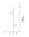
- the device 1 has a position "a” in which the angular velocity "V” of peripheral movement of the preform is decelerated (V min) with respect to the average speed (v avg).
- the "a" position may coincide with the entry of the preform into a low-pitch conveying equipment, such as a preform heating furnace which may have a 50 mm pitch between the preforms.
- a low-pitch conveying equipment such as a preform heating furnace which may have a 50 mm pitch between the preforms.
- V max the peripheral speed
- the position "b” may coincide with the delivery of the preform to a high-pitch conveying equipment, such as a blowing machine may have a pitch of 500 mm between the blowing stations.
- the device 1 is limited in the scroll speed change coefficient that can be obtained. Indeed, the greater the angular movement of the gripping arm 5, the greater the distance of the gripper 9 to the axis of rotation of the wheel 4 varies.
- two cam-controlled arms were developed. In addition to the cam path 3 controlling the relative angular position of the arm 5, is added another camming path controlling a radial translation of the clamp 9 on the arm 5. There is a need to obtain a scroll speed change of the objects with a simpler mechanism.
- the device 1 is limited in cadence, that is to say in the number of objects transferred per hour. This limit is reached faster than the rate of change of scroll speed is high. Indeed, the increase in the coefficient causes a slope 3b more inclined to further accelerate or decelerate locally the clamp 9. This results in mechanical stresses even higher than the wheel 4 rotates quickly. A need exists to obtain a coefficient of change of speed of scrolling less limited in time.
- the invention proposes a device for increasing the pitch for positive transfer of objects, a transfer mechanism and a preform blowing installation that meet at least one of the aforementioned needs.
- An object of the invention is to simplify the pitch increase device and / or to make it less limited in the rate of transferred objects.
- Such a device is mainly adapted to transfer objects whose section is circular and corresponds to the reference circle.
- the object transferred may have a guide section cooperating with the notches which is not purely circular.
- the guide section of the transferred object is then advantageously inscribed in the reference circle.
- said object slides along the first guide being pushed by the upstream side of the notch of the first wheel.
- the downstream flank of the notch of the second wheel that will receive this object does not interfere with this object although this notch of the second wheel has a peripheral speed faster than the object.
- the same object is pushed by the upstream side of the notch of the second wheel and the object slides along the second guide.
- the downstream flank of the notch of the first wheel that this object has just left does not interfere with the object that is moving away. In other words, the object could pass from the first wheel with a low peripheral scroll speed to the second wheel with a higher peripheral scroll speed and this in a simple way. In addition, there is no fast moving part.
- the pitch increasing device is then less limited in the rate of objects to be transferred than the device 1 described above.
- the downstream edge of each of the notches of at least one of the wheels is defined by the casing of the set of reference circles of the notch corresponding to said notch in the opposite wheel, during the rotation of the wheels.
- the downstream flank of the notches of the second wheel is conjugated to the input of a reference circle in said notch.
- this notch of the second wheel begins to hold the object before it arrives at the median plane, it allows to properly press the object on the upstream side of the notch of the first wheel.
- the downstream side of each of the notches of the first wheel is conjugated to the output of a reference circle of the second wheel out of this notch. This allows this notch to continue holding the object beyond the median plane. This makes it possible to flatten the object on the upstream side of the notch of the second wheel.
- the centers of the reference circles of each of the notches of a wheel are distributed along a circle coaxial with the axis of rotation of the corresponding wheel.
- the connecting mechanism is designed to secure the rotation of the first notched wheel and the rotation of the second notched wheel so that periodically the center of the reference circle of a notch of the first wheel reaches the plane. median simultaneously with the arrival of the center of the reference circle of a notch of the second wheel.
- the invention also relates to a transfer mechanism consisting of a first pitch-increasing device, followed by a second pitch-increasing device.
- the second wheel of the first device is the first wheel of the second device.
- the successive accumulation of two pairs of notched wheels makes it possible to multiply the rate of increase of the pitch. This also allows the second wheel of the second device to rotate in the same direction of rotation as the first wheel of the first device. This simplifies the implementation of the transfer mechanism.
- Each of the pitch increasing devices has a rate of increase equal to the second peripheral step divided by the first peripheral step.
- the downstream edge of each of the notches of the wheel common to the first and second devices is defined by the envelope of the set of reference circles of the notch corresponding to said notch in the opposite wheel belonging to the device of more great rate of increase, when rotating the wheels. This allows the notches of the common wheel to be optimized for the wheel pair of greater rate of pitch increase.
- the diameter and the number of notches of the wheels of the second pitch-increasing device are adapted so that the two rates of increase are similar.
- the notches of the wheel common to the two pitch increasing devices are substantially optimized both for their cooperation with the notches of the first wheel of the first device and with the notches of the second wheel of the second device.
- the auxiliary transfer mechanism comprises an aforementioned pitch-increasing device or comprises a aforementioned transfer mechanism.
- a device 50 comprises a first wheel 51 rotated by a drive means not shown in a direction 52 indicated by the arrow.
- the first wheel 51 is movable about a first axis 53 of rotation and comprises a succession of first notches 54a, 54b, 54c, 54d and is surrounded by a first guide 55 circular and coaxial with the first axis 53.
- the device 50 comprises a second wheel 56 movable in rotation about a second axis 57 of rotation.
- the device 50 comprises a mechanism for connecting the rotations of the first and second wheels 51, 56 so that the wheel 56 is driven in a direction opposite to the direction of rotation of the first wheel 51.
- the first and second axes 53, 57 of rotation are substantially parallel and contained in a median plane 58 .
- the second wheel 56 also has a succession of second notches 59a, 59b, 59c and is surrounded by a second guide 60 circular and coaxial with the second axis 57.
- Each of the first notches 54a, 54b, 54c, 54d have a concave shape open radially outwardly of the first wheel 51 and is constituted, on either side of the point of the concave shape closest to the first axis 53, a first upstream flank 61a, 61b, 61c, 61d and a first downstream flank 62a, 62b, 62c, 62d.
- each of the second notches 59a, 59b, 59c has a concave shape open radially outwardly of the second wheel 56 and is constituted, on either side of the point of the concave shape closest to the second axis 57 by a second upstream flank 63a, 63b, 63c and a second downstream flank 64a, 64b, 64c.
- the downstream side is the one that passes through the median plane 58 between the axes 53, 57 the first and the upstream side is the one that passes through it last.
- the direction of rotation of the first and second wheels 51, 56 also makes it possible to define an upstream side of the median plane 58 which is the one through which the notches of the two Wheels 51, 56 approach the median plane 58 between the axes 53, 57.
- the other side of the median plane 58 is a downstream side.
- the first guide 55 extends from the median plane 58 and surrounds the first wheel 51 on the upstream side of the median plane 58.
- the second guide 60 extends from the median plane 58 and surrounds the second wheel 56 on the downstream side of the median plane 58.
- a reference circle is defined which is circumscribed between the first corresponding upstream flank 61a, 61b, 61c, 61d and the first guide 55.
- a reference circle is defined which is circumscribed between the corresponding second upstream flank 63a, 63b, 63c and the second guide 60.
- the reference circles of the first notches have centers 65a, 65b, 65c, 65d distributed equidistantly along a path 66 in a first peripheral step 67 .
- the reference circles of the second recesses have centers 68a, 68b, 68c divided equidistantly along a path 69 according to a second step 70 device.
- the reference circles of the first notches are all of the same diameter.
- the reference circles of the second notches are advantageously of the same diameter and are also advantageously identical to the diameter of the reference circles of the first notches.
- the trajectories 66, 69 are circular and coaxial with the axis 53, 57 corresponding rotation. However, slight differences in diameter are possible without preventing the operation of the device 50.
- the first and second upstream flanks are circular. They may, however, be constituted by two abutment zones circumscribed to the reference circle of the corresponding notch.
- the trajectories 66, 69 are tangent to each other at the point of intersection with the median plane 58.
- the trajectories 66, 69 may not have a common point or be intersecting provided that their point of intersection with the median plane 58 remains close to the diameters of the reference circles.
- the rotational driving means and the rotational linking mechanism are designed so that periodically a center of the reference circle of the first notches (the center 65c in figure 3 ) reaches the median plane at the same time as a reference circle center of the second notches (center 68b in figure 3 ). This moment will be called a moment of coincidence.
- the first wheel 51 is driven at such a speed that the center 65b of the reference circle immediately upstream of the median plane 58 passes through the first peripheral step 67, while the second wheel 56 is driven at a speed such that the center 68a of the reference circle immediately upstream of the median plane 58 traverses the second peripheral pitch.
- an object such as a preform, having a circular section 71 substantially equal to the diameter common to all the reference circles can be received between the first notch 54b and the first guide 55, be pushed by the first upstream flank 61b, slide along the first guide 55 to the median plane 58.
- This object can then be supported by the corresponding second notch 59a, then be pushed by the second upstream flank 63a and slide along the second guide 60.
- the successive objects are separated from each other. others from a distance equal to the first peripheral step 67 and then transit along the second guide 60 where they are then spaced a distance equal to the second peripheral pitch 70.
- the figure 4 illustrates the position of the objects in the notches after a duration following the moment of coincidence of the figure 3 equal to one quarter of the period between two moments of coincidence. That is, the center 65c of the reference circle of the first notch 54c has traveled a quarter of the first peripheral pitch 67 and the center 68b of the reference circle of the second notch 59b has traveled a quarter of the second pitch 70 peripheral. In other words, the first downstream flank 62c is sufficiently far from the center 65c so that the object driven by the second notch 59b does not interfere with the first wheel 51.
- the center 65b of the reference circle of the notch 54b is upstream of the median plane 58 by a distance equal to three quarters of the first peripheral pitch 67.
- the second downstream flank 64a is sufficiently far from the center 68a for the object driven by the first notch 54b does not interfere with second wheel 56.
- the reference circle of the second notch 59b along the first sidewall 62c downstream This allows the slot 54c to continue to press the object supported by the second slot 59b against the second side 63b upstream.
- the reference circle of the first notch 54b runs along the second sidewall 64b downstream. This allows the second notch 59a to retain the object of the first notch 54b and hold it pressed against the first flank 61b upstream.
- the object transferred is a preform 72 having an axis 73 and comprising a neck 74, a flange 75 and a main portion 76 intended to be stretched and blown.
- the guide section 71 of the preform 72 is located below the flange 75 on the side of the main portion 76.
- the guide section 71 is cylindrical and coaxial with the axis 73 and the flange 75 extends radially beyond the guide section 71.
- the first and second wheels 51, 56 are machined in plates of similar thickness and each having an upper surface 77 .
- the wheels are arranged so that their upper surfaces 77 are at the same height.
- the guide section 71 is gripped by the first notch 54c and by the second notch 59b opposite ( figure 3 ).
- the flange 75 is then substantially supported by a half on the upper surface 77 of the first wheel 51 and substantially by another half on the upper surface 77 of the second wheel 56. This allows the axis 73 of the preform 72 to remain substantially vertical and parallel to the first and second axes 53, 57 of rotation.
- the first guide 55 comprises a main portion 78 and an extension 79.
- the main portion 78 has a surface 78a located at the same height as the upper surfaces 77 of the two wheels 51, 56.
- the flange 75 is supported firstly on the upper surface 77 of the first wheel 51 and secondly on the upper surface 78a of the main part 78.
- the two parts of the flange 75 in support are diametrically opposite with respect to the axis 73 of the flange, which gives good mechanical stability to the preform 72.
- the main portion 78 surrounds the first wheel 51 to the circle 69 of the second wheel 56.
- the extender 79 takes over the main portion 78 to continue holding the preform 72 in the first notch until the preform 72 reaches the median plane 58.
- the neck 74 has an opening 74a, also called a drinking head 74a, a thread 74b extending between the opening 74a and the collar 75.
- the neck has an edge 74c whose radially outer surface is cylindrical and smooth and extends axially on a few millimeters high from the rim 74a to the thread 74b.
- Extender 79 is a wire that extends above upper surfaces 78a, 77 at the height of smooth edge 74c.
- the extension 79 can thus guide the preform 72 as it enters the second notch 59a.
- the extension 79 makes it possible to maintain the axis 73 of the preform 72 in vertical position while the flange 75 leaves the main portion 78 of the first guide 55 to slide over the second wheel 56.
- the extender 79 keeps the guide section 71 pressed against the first flank 61b, 61c upstream and prevents it from leaving the location determined by the reference circle of the first notch 54b, 54c.
- the guide section 71 can enter the second notch 59a, 59b without hitting the second wheel 56.
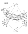
- a preform blowing installation 100 comprises successively following the path of the preforms 72: a preheating furnace 101 , an auxiliary transfer mechanism 102 , a main transfer mechanism 103 and a blowing machine 104 .
- the preheating furnace 101 comprises a chain 105, equipped with a succession of gripping mechanisms preforms 72 by their neck 74. This mechanism is often called “spin”. Along the chain 105, the preforms 72 are spaced apart from each other by a distance 106 that we will call “no primary device 106". To reduce the size of the oven, it is often sought to increase the density of the preforms 72 in the oven.
- the pitch 106 primary device may be 50 mm for example.
- the chain 105 is driven by two wheels 107 , one of which, the wheel A, is located at least partly outside the oven 101.
- the spinners withdraw preforms 72 and these are taken in charge between notches 108 of the wheel A and a guide 109 surrounding the wheel A.
- the wheel A also cooperates with a preform feed wheel 110 .
- the auxiliary transfer mechanism 102 is composed of first and second pitch increasing devices 111 and 112, respectively , as previously described.
- the first device 111 for increasing pitch is constituted by the wheel A, as the first wheel, accompanied by its guide 109, and by a wheel B, as the second wheel, accompanied by a guide 113.
- the preforms 72 are driven by the wheel B in a peripheral pitch 114 which may be 70 mm for example.
- the first pitch increasing device 111 has a rate of increase of 1.4.
- the second pitch increasing device 112 is constituted by the wheel B, as the first wheel accompanied by its guide 113, and by a wheel C as a second wheel accompanied by a guide 115.
- the wheel B is common to the first and second pitch increasing devices 111, 112.
- the preforms 112 are driven by the wheel C in a peripheral pitch 116 which may be 120 mm for example and which we will call "pitch 116 intermediate device".
- the second pitch increasing device 112 has a rate of increase of 1.71.
- the main transfer mechanism 103 comprises a series of arms 117 on a wheel (not shown) with an axis 118. Each of the arms 117 is rotatable about an auxiliary axis 119 . The various axes 119 are distributed along a circle coaxial with the axis 118. A single arm 117 has been shown. Each arm 117 comprises a clamp 120 whose radial relative position is controlled by a cam path 121 and whose relative angular position is controlled by a cam path 122 .
- the main transfer mechanism 103 has a mean preform drive speed which is slowed to coincide with the wheel C at the intermediate peripheral pitch 116 and which is accelerated with respect to the blowing machine 104 to coincide with a pitch 123 final device.
- the final peripheral pitch 123 corresponds to the distance between two successive stretch blow molding stations 124 . This distance may be 500 mm for example so that the main transfer mechanism 103 then has a step increase rate of 4.16.
- the wheel B is illustrated in its portion which cooperates with the wheel A.
- the wheel B has notches 129 comprising a downstream sidewall 126 which is conjugated with the displacement of the reference circles driven by the wheel C with which the wheel B has the rate of increase of not the highest.
- a dotted line 126a is shown conjugated with the reference circles driven by wheel A is shown in dotted lines.
- the profile of the downstream flank 126 which has been retained is one of the conjugate profiles which has the minimum of material .
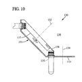
- a pitch increasing device 130 may be made with a first wheel 131 movable about a first axis 132 and a second wheel 133 movable about a second axis 134.
- the first wheel 131 has notches 135 designed to be in the same plane as the second wheel 133 when this notch comes opposite the wheel 133.
- the first and second axes 132, 134 are intersecting and are contained in a median plane 136.
- the device 130 includes a cone-shaped guide 137 surrounding the first wheel 131, and an extension 138 extending the preform guide to the median plane 136 at a location where the conical guide 137 will interfere with the second wheel 133.
- first and second axes 132, 134 could be strictly non-coplanar.
- the median plane of the pitch increase device would then be the one relative to which the first and second axes would generally have the minimum angle.
Landscapes
- Engineering & Computer Science (AREA)
- Mechanical Engineering (AREA)
- Manufacturing & Machinery (AREA)
- Specific Conveyance Elements (AREA)
- Blow-Moulding Or Thermoforming Of Plastics Or The Like (AREA)
Applications Claiming Priority (1)
| Application Number | Priority Date | Filing Date | Title |
|---|---|---|---|
| FR1256823A FR2993259B1 (fr) | 2012-07-13 | 2012-07-13 | Dispositif d'augmentation de pas pour transfert positif et individuel d'objets |
Publications (2)
| Publication Number | Publication Date |
|---|---|
| EP2684822A1 true EP2684822A1 (de) | 2014-01-15 |
| EP2684822B1 EP2684822B1 (de) | 2014-12-03 |
Family
ID=47424986
Family Applications (1)
| Application Number | Title | Priority Date | Filing Date |
|---|---|---|---|
| EP13173813.0A Not-in-force EP2684822B1 (de) | 2012-07-13 | 2013-06-26 | Vorrichtung zum Vergrössern eines Schritts für eine positive und individuelle Übertragung von Objekten |
Country Status (3)
| Country | Link |
|---|---|
| EP (1) | EP2684822B1 (de) |
| CN (1) | CN103538913B (de) |
| FR (1) | FR2993259B1 (de) |
Cited By (3)
| Publication number | Priority date | Publication date | Assignee | Title |
|---|---|---|---|---|
| WO2016001332A1 (fr) * | 2014-07-02 | 2016-01-07 | Serac Group | Installation de transport de récipients |
| IT201800007415A1 (it) * | 2018-07-23 | 2020-01-23 | Dispositivo di guida-collo per linee di imbottigliamento | |
| EP3380420B1 (de) * | 2015-11-25 | 2022-04-20 | Esomatec GmbH | Vorrichtung und verfahren zum vereinzeln und/oder prüfen von behältern |
Families Citing this family (1)
| Publication number | Priority date | Publication date | Assignee | Title |
|---|---|---|---|---|
| DE102018208956A1 (de) * | 2018-06-06 | 2019-12-12 | Bausch + Ströbel Maschinenfabrik Ilshofen GmbH + Co. KG | Weichenvorrichtung |
Citations (3)
| Publication number | Priority date | Publication date | Assignee | Title |
|---|---|---|---|---|
| US4790741A (en) * | 1987-08-07 | 1988-12-13 | Toyo Seikan Kaisha, Ltd. | Apparatus for preparing heat-set plastic hollow vessel |
| WO2001042113A1 (en) * | 1999-12-08 | 2001-06-14 | Central Bottling International Limited | Handling apparatus for use in a bottling plant to handle bottles with neck rings |
| WO2011113710A1 (en) * | 2010-03-15 | 2011-09-22 | Crown Packaging Technology, Inc. | Container manufacture |
Family Cites Families (5)
| Publication number | Priority date | Publication date | Assignee | Title |
|---|---|---|---|---|
| FR2709264B1 (fr) * | 1993-08-26 | 1995-10-27 | Sidel Sa | Installation de fabrication de récipients par soufflage de préformes en matière plastique. |
| ITRE20040039A1 (it) * | 2004-04-23 | 2004-07-23 | Sacmi | Manipolazione di corpi di materiale polimerico allo stato liquido viscoso nella formatura a compressione d'oggetti di plastica. |
| US7632089B2 (en) * | 2004-05-07 | 2009-12-15 | Graham Packaging Pet Technologies, Inc. | Take out and cooling system and method |
| FR2895384B1 (fr) * | 2005-12-26 | 2009-10-30 | Sidel Sas | Dispositif de transfert selectif d'articles a grande cadence, application au tri de bouteilles, machine de soufflage comportant un tel dispositif |
| CN102358025B (zh) * | 2011-09-07 | 2014-04-16 | 铨宝工业股份有限公司 | 一种吹塑成形机及其分流方法 |
-
2012
- 2012-07-13 FR FR1256823A patent/FR2993259B1/fr not_active Expired - Fee Related
-
2013
- 2013-06-26 EP EP13173813.0A patent/EP2684822B1/de not_active Not-in-force
- 2013-07-11 CN CN201310291324.0A patent/CN103538913B/zh not_active Expired - Fee Related
Patent Citations (3)
| Publication number | Priority date | Publication date | Assignee | Title |
|---|---|---|---|---|
| US4790741A (en) * | 1987-08-07 | 1988-12-13 | Toyo Seikan Kaisha, Ltd. | Apparatus for preparing heat-set plastic hollow vessel |
| WO2001042113A1 (en) * | 1999-12-08 | 2001-06-14 | Central Bottling International Limited | Handling apparatus for use in a bottling plant to handle bottles with neck rings |
| WO2011113710A1 (en) * | 2010-03-15 | 2011-09-22 | Crown Packaging Technology, Inc. | Container manufacture |
Cited By (4)
| Publication number | Priority date | Publication date | Assignee | Title |
|---|---|---|---|---|
| WO2016001332A1 (fr) * | 2014-07-02 | 2016-01-07 | Serac Group | Installation de transport de récipients |
| EP3380420B1 (de) * | 2015-11-25 | 2022-04-20 | Esomatec GmbH | Vorrichtung und verfahren zum vereinzeln und/oder prüfen von behältern |
| IT201800007415A1 (it) * | 2018-07-23 | 2020-01-23 | Dispositivo di guida-collo per linee di imbottigliamento | |
| WO2020020702A1 (en) * | 2018-07-23 | 2020-01-30 | Robino & Galandrino S.P.A. | Neck guiding device for bottling lines |
Also Published As
| Publication number | Publication date |
|---|---|
| EP2684822B1 (de) | 2014-12-03 |
| FR2993259B1 (fr) | 2014-08-29 |
| FR2993259A1 (fr) | 2014-01-17 |
| CN103538913A (zh) | 2014-01-29 |
| CN103538913B (zh) | 2016-08-31 |
Similar Documents
| Publication | Publication Date | Title |
|---|---|---|
| EP2178778B1 (de) | Gefässfördervorrichtung zur trennung eines hauptgefässflusses in mehrere sekundärflüsse | |
| EP1846218B1 (de) | Drehvorrichtung zum transferieren von behältern | |
| EP1723060B1 (de) | Fördereinrichtung mit einem verbesserten übergabearm | |
| EP2686259B1 (de) | Übertragungsvorrichtung mit einem greifer | |
| EP2382144B1 (de) | Anlage zur herstellung von gefässen mit einem übertragungsrad mit verstellbarem schritt | |
| EP2328824B1 (de) | Verfahren und vorrichtung zur positionierung von behältern und anlage zur behandlung von behältern mit verschiedenen querschnitten | |
| EP2684822B1 (de) | Vorrichtung zum Vergrössern eines Schritts für eine positive und individuelle Übertragung von Objekten | |
| EP2432715A1 (de) | Verfahren zum transport von behältern durch teilweises abstützen der letzteren und das verfahren implementierende einrichtung | |
| EP1781460B1 (de) | Vorformförderanlage mit vorrichtung zum auswurf schlecht erfasster vorformen | |
| EP3230185B1 (de) | Vorrichtung zur herstellung eines behälters mit zwei rollen zur ansteuerung eines behälters | |
| EP2509769B1 (de) | Blasformmaschine und verfahren mi vorladung von vorformen | |
| EP3538459B1 (de) | System zum befördern von gegenständen aus einem thermoplastischen material mit einem hohlkörper mit einem hals | |
| CA2617067A1 (fr) | Dispositif de chargement ou de dechargement de recipients comportant un col sur un element de transport | |
| EP3898176B1 (de) | Vorrichtung zum fördern von vorformen und verfahren zur steuerung solch einer vorrichtung zur winkelmässigen indexierung der vorformen in einer referenzposition | |
| FR2801045A1 (fr) | Systeme de convoyage d'entites discretes comportant un dispositif de repartition et installation de soufflage de recipients munie d'un tel systeme | |
| FR2639614A1 (fr) | Procede pour emballer des cigarettes dans des paquets durs a dessus basculant | |
| WO2012130973A1 (fr) | Dispositif de transfert de recipients avec indexation angulaire par contact entre un element d'indexation et un troncon cylindrique du recipient | |
| WO2016001333A1 (fr) | Installation de transport de recipients | |
| EP0573352B1 (de) | Einrichtung zum Laden von Behältern auf ein Transportglied | |
| EP2861514B1 (de) | Übertragungsvorrichtung für hohlkörper mit variabler teilung | |
| EP2444251A1 (de) | Tintenstrahldruckmaschine | |
| EP4594079A1 (de) | Verfahren zum überführen von vorformlingen auf einen förderer | |
| WO2020128406A1 (fr) | Procédé de contrôle de la synchronisation de deux roues de transport de corps creux | |
| WO2002053458A1 (fr) | Procede et dispositif pour amener et positionner des boites a un poste d'emboitage | |
| FR2810651A1 (fr) | Dispositif pour la constitution de lots successifs d'articles comprenant des moyens de transfert des articles, et installation comprenant ce dispositif |
Legal Events
| Date | Code | Title | Description |
|---|---|---|---|
| PUAI | Public reference made under article 153(3) epc to a published international application that has entered the european phase |
Free format text: ORIGINAL CODE: 0009012 |
|
| AK | Designated contracting states |
Kind code of ref document: A1 Designated state(s): AL AT BE BG CH CY CZ DE DK EE ES FI FR GB GR HR HU IE IS IT LI LT LU LV MC MK MT NL NO PL PT RO RS SE SI SK SM TR |
|
| AX | Request for extension of the european patent |
Extension state: BA ME |
|
| GRAP | Despatch of communication of intention to grant a patent |
Free format text: ORIGINAL CODE: EPIDOSNIGR1 |
|
| 17P | Request for examination filed |
Effective date: 20140523 |
|
| RBV | Designated contracting states (corrected) |
Designated state(s): AL AT BE BG CH CY CZ DE DK EE ES FI FR GB GR HR HU IE IS IT LI LT LU LV MC MK MT NL NO PL PT RO RS SE SI SK SM TR |
|
| INTG | Intention to grant announced |
Effective date: 20140630 |
|
| GRAS | Grant fee paid |
Free format text: ORIGINAL CODE: EPIDOSNIGR3 |
|
| GRAA | (expected) grant |
Free format text: ORIGINAL CODE: 0009210 |
|
| AK | Designated contracting states |
Kind code of ref document: B1 Designated state(s): AL AT BE BG CH CY CZ DE DK EE ES FI FR GB GR HR HU IE IS IT LI LT LU LV MC MK MT NL NO PL PT RO RS SE SI SK SM TR |
|
| REG | Reference to a national code |
Ref country code: GB Ref legal event code: FG4D Free format text: NOT ENGLISH |
|
| REG | Reference to a national code |
Ref country code: AT Ref legal event code: REF Ref document number: 699226 Country of ref document: AT Kind code of ref document: T Effective date: 20141215 Ref country code: CH Ref legal event code: EP |
|
| REG | Reference to a national code |
Ref country code: IE Ref legal event code: FG4D Free format text: LANGUAGE OF EP DOCUMENT: FRENCH |
|
| REG | Reference to a national code |
Ref country code: DE Ref legal event code: R096 Ref document number: 602013000560 Country of ref document: DE Effective date: 20150115 |
|
| REG | Reference to a national code |
Ref country code: NL Ref legal event code: VDEP Effective date: 20141203 |
|
| REG | Reference to a national code |
Ref country code: AT Ref legal event code: MK05 Ref document number: 699226 Country of ref document: AT Kind code of ref document: T Effective date: 20141203 |
|
| PG25 | Lapsed in a contracting state [announced via postgrant information from national office to epo] |
Ref country code: FI Free format text: LAPSE BECAUSE OF FAILURE TO SUBMIT A TRANSLATION OF THE DESCRIPTION OR TO PAY THE FEE WITHIN THE PRESCRIBED TIME-LIMIT Effective date: 20141203 Ref country code: NO Free format text: LAPSE BECAUSE OF FAILURE TO SUBMIT A TRANSLATION OF THE DESCRIPTION OR TO PAY THE FEE WITHIN THE PRESCRIBED TIME-LIMIT Effective date: 20150303 Ref country code: LT Free format text: LAPSE BECAUSE OF FAILURE TO SUBMIT A TRANSLATION OF THE DESCRIPTION OR TO PAY THE FEE WITHIN THE PRESCRIBED TIME-LIMIT Effective date: 20141203 Ref country code: NL Free format text: LAPSE BECAUSE OF FAILURE TO SUBMIT A TRANSLATION OF THE DESCRIPTION OR TO PAY THE FEE WITHIN THE PRESCRIBED TIME-LIMIT Effective date: 20141203 Ref country code: ES Free format text: LAPSE BECAUSE OF FAILURE TO SUBMIT A TRANSLATION OF THE DESCRIPTION OR TO PAY THE FEE WITHIN THE PRESCRIBED TIME-LIMIT Effective date: 20141203 |
|
| REG | Reference to a national code |
Ref country code: LT Ref legal event code: MG4D |
|
| REG | Reference to a national code |
Ref country code: FR Ref legal event code: PLFP Year of fee payment: 3 |
|
| PG25 | Lapsed in a contracting state [announced via postgrant information from national office to epo] |
Ref country code: GR Free format text: LAPSE BECAUSE OF FAILURE TO SUBMIT A TRANSLATION OF THE DESCRIPTION OR TO PAY THE FEE WITHIN THE PRESCRIBED TIME-LIMIT Effective date: 20150304 Ref country code: SE Free format text: LAPSE BECAUSE OF FAILURE TO SUBMIT A TRANSLATION OF THE DESCRIPTION OR TO PAY THE FEE WITHIN THE PRESCRIBED TIME-LIMIT Effective date: 20141203 Ref country code: LV Free format text: LAPSE BECAUSE OF FAILURE TO SUBMIT A TRANSLATION OF THE DESCRIPTION OR TO PAY THE FEE WITHIN THE PRESCRIBED TIME-LIMIT Effective date: 20141203 Ref country code: RS Free format text: LAPSE BECAUSE OF FAILURE TO SUBMIT A TRANSLATION OF THE DESCRIPTION OR TO PAY THE FEE WITHIN THE PRESCRIBED TIME-LIMIT Effective date: 20141203 Ref country code: HR Free format text: LAPSE BECAUSE OF FAILURE TO SUBMIT A TRANSLATION OF THE DESCRIPTION OR TO PAY THE FEE WITHIN THE PRESCRIBED TIME-LIMIT Effective date: 20141203 Ref country code: AT Free format text: LAPSE BECAUSE OF FAILURE TO SUBMIT A TRANSLATION OF THE DESCRIPTION OR TO PAY THE FEE WITHIN THE PRESCRIBED TIME-LIMIT Effective date: 20141203 Ref country code: CY Free format text: LAPSE BECAUSE OF FAILURE TO SUBMIT A TRANSLATION OF THE DESCRIPTION OR TO PAY THE FEE WITHIN THE PRESCRIBED TIME-LIMIT Effective date: 20141203 |
|
| PG25 | Lapsed in a contracting state [announced via postgrant information from national office to epo] |
Ref country code: CZ Free format text: LAPSE BECAUSE OF FAILURE TO SUBMIT A TRANSLATION OF THE DESCRIPTION OR TO PAY THE FEE WITHIN THE PRESCRIBED TIME-LIMIT Effective date: 20141203 Ref country code: PT Free format text: LAPSE BECAUSE OF FAILURE TO SUBMIT A TRANSLATION OF THE DESCRIPTION OR TO PAY THE FEE WITHIN THE PRESCRIBED TIME-LIMIT Effective date: 20150403 Ref country code: RO Free format text: LAPSE BECAUSE OF FAILURE TO SUBMIT A TRANSLATION OF THE DESCRIPTION OR TO PAY THE FEE WITHIN THE PRESCRIBED TIME-LIMIT Effective date: 20141203 Ref country code: EE Free format text: LAPSE BECAUSE OF FAILURE TO SUBMIT A TRANSLATION OF THE DESCRIPTION OR TO PAY THE FEE WITHIN THE PRESCRIBED TIME-LIMIT Effective date: 20141203 Ref country code: SK Free format text: LAPSE BECAUSE OF FAILURE TO SUBMIT A TRANSLATION OF THE DESCRIPTION OR TO PAY THE FEE WITHIN THE PRESCRIBED TIME-LIMIT Effective date: 20141203 |
|
| PG25 | Lapsed in a contracting state [announced via postgrant information from national office to epo] |
Ref country code: PL Free format text: LAPSE BECAUSE OF FAILURE TO SUBMIT A TRANSLATION OF THE DESCRIPTION OR TO PAY THE FEE WITHIN THE PRESCRIBED TIME-LIMIT Effective date: 20141203 Ref country code: IS Free format text: LAPSE BECAUSE OF FAILURE TO SUBMIT A TRANSLATION OF THE DESCRIPTION OR TO PAY THE FEE WITHIN THE PRESCRIBED TIME-LIMIT Effective date: 20150403 |
|
| REG | Reference to a national code |
Ref country code: DE Ref legal event code: R097 Ref document number: 602013000560 Country of ref document: DE |
|
| PLBE | No opposition filed within time limit |
Free format text: ORIGINAL CODE: 0009261 |
|
| STAA | Information on the status of an ep patent application or granted ep patent |
Free format text: STATUS: NO OPPOSITION FILED WITHIN TIME LIMIT |
|
| PG25 | Lapsed in a contracting state [announced via postgrant information from national office to epo] |
Ref country code: DK Free format text: LAPSE BECAUSE OF FAILURE TO SUBMIT A TRANSLATION OF THE DESCRIPTION OR TO PAY THE FEE WITHIN THE PRESCRIBED TIME-LIMIT Effective date: 20141203 |
|
| 26N | No opposition filed |
Effective date: 20150904 |
|
| PG25 | Lapsed in a contracting state [announced via postgrant information from national office to epo] |
Ref country code: MC Free format text: LAPSE BECAUSE OF FAILURE TO SUBMIT A TRANSLATION OF THE DESCRIPTION OR TO PAY THE FEE WITHIN THE PRESCRIBED TIME-LIMIT Effective date: 20141203 |
|
| PG25 | Lapsed in a contracting state [announced via postgrant information from national office to epo] |
Ref country code: SI Free format text: LAPSE BECAUSE OF FAILURE TO SUBMIT A TRANSLATION OF THE DESCRIPTION OR TO PAY THE FEE WITHIN THE PRESCRIBED TIME-LIMIT Effective date: 20141203 Ref country code: LU Free format text: LAPSE BECAUSE OF FAILURE TO SUBMIT A TRANSLATION OF THE DESCRIPTION OR TO PAY THE FEE WITHIN THE PRESCRIBED TIME-LIMIT Effective date: 20150626 |
|
| REG | Reference to a national code |
Ref country code: IE Ref legal event code: MM4A |
|
| PG25 | Lapsed in a contracting state [announced via postgrant information from national office to epo] |
Ref country code: IE Free format text: LAPSE BECAUSE OF NON-PAYMENT OF DUE FEES Effective date: 20150626 |
|
| REG | Reference to a national code |
Ref country code: FR Ref legal event code: PLFP Year of fee payment: 4 |
|
| PG25 | Lapsed in a contracting state [announced via postgrant information from national office to epo] |
Ref country code: MT Free format text: LAPSE BECAUSE OF FAILURE TO SUBMIT A TRANSLATION OF THE DESCRIPTION OR TO PAY THE FEE WITHIN THE PRESCRIBED TIME-LIMIT Effective date: 20141203 |
|
| REG | Reference to a national code |
Ref country code: CH Ref legal event code: PL |
|
| PG25 | Lapsed in a contracting state [announced via postgrant information from national office to epo] |
Ref country code: LI Free format text: LAPSE BECAUSE OF NON-PAYMENT OF DUE FEES Effective date: 20160630 Ref country code: CH Free format text: LAPSE BECAUSE OF NON-PAYMENT OF DUE FEES Effective date: 20160630 |
|
| REG | Reference to a national code |
Ref country code: FR Ref legal event code: PLFP Year of fee payment: 5 |
|
| PG25 | Lapsed in a contracting state [announced via postgrant information from national office to epo] |
Ref country code: HU Free format text: LAPSE BECAUSE OF FAILURE TO SUBMIT A TRANSLATION OF THE DESCRIPTION OR TO PAY THE FEE WITHIN THE PRESCRIBED TIME-LIMIT; INVALID AB INITIO Effective date: 20130626 Ref country code: BG Free format text: LAPSE BECAUSE OF FAILURE TO SUBMIT A TRANSLATION OF THE DESCRIPTION OR TO PAY THE FEE WITHIN THE PRESCRIBED TIME-LIMIT Effective date: 20141203 |
|
| PG25 | Lapsed in a contracting state [announced via postgrant information from national office to epo] |
Ref country code: BE Free format text: LAPSE BECAUSE OF NON-PAYMENT OF DUE FEES Effective date: 20150630 |
|
| PGFP | Annual fee paid to national office [announced via postgrant information from national office to epo] |
Ref country code: FR Payment date: 20170523 Year of fee payment: 5 Ref country code: DE Payment date: 20170522 Year of fee payment: 5 |
|
| PG25 | Lapsed in a contracting state [announced via postgrant information from national office to epo] |
Ref country code: TR Free format text: LAPSE BECAUSE OF FAILURE TO SUBMIT A TRANSLATION OF THE DESCRIPTION OR TO PAY THE FEE WITHIN THE PRESCRIBED TIME-LIMIT Effective date: 20141203 |
|
| PGFP | Annual fee paid to national office [announced via postgrant information from national office to epo] |
Ref country code: IT Payment date: 20170522 Year of fee payment: 5 |
|
| GBPC | Gb: european patent ceased through non-payment of renewal fee |
Effective date: 20170626 |
|
| PG25 | Lapsed in a contracting state [announced via postgrant information from national office to epo] |
Ref country code: GB Free format text: LAPSE BECAUSE OF NON-PAYMENT OF DUE FEES Effective date: 20170626 |
|
| PG25 | Lapsed in a contracting state [announced via postgrant information from national office to epo] |
Ref country code: SM Free format text: LAPSE BECAUSE OF FAILURE TO SUBMIT A TRANSLATION OF THE DESCRIPTION OR TO PAY THE FEE WITHIN THE PRESCRIBED TIME-LIMIT Effective date: 20141203 |
|
| PG25 | Lapsed in a contracting state [announced via postgrant information from national office to epo] |
Ref country code: MK Free format text: LAPSE BECAUSE OF FAILURE TO SUBMIT A TRANSLATION OF THE DESCRIPTION OR TO PAY THE FEE WITHIN THE PRESCRIBED TIME-LIMIT Effective date: 20141203 |
|
| PG25 | Lapsed in a contracting state [announced via postgrant information from national office to epo] |
Ref country code: AL Free format text: LAPSE BECAUSE OF FAILURE TO SUBMIT A TRANSLATION OF THE DESCRIPTION OR TO PAY THE FEE WITHIN THE PRESCRIBED TIME-LIMIT Effective date: 20141203 |
|
| REG | Reference to a national code |
Ref country code: DE Ref legal event code: R119 Ref document number: 602013000560 Country of ref document: DE |
|
| PG25 | Lapsed in a contracting state [announced via postgrant information from national office to epo] |
Ref country code: FR Free format text: LAPSE BECAUSE OF NON-PAYMENT OF DUE FEES Effective date: 20180630 Ref country code: IT Free format text: LAPSE BECAUSE OF NON-PAYMENT OF DUE FEES Effective date: 20180626 Ref country code: DE Free format text: LAPSE BECAUSE OF NON-PAYMENT OF DUE FEES Effective date: 20190101 |