EP2684823B1 - Dispositif de formation et de transfert de piles d'emballages blister - Google Patents
Dispositif de formation et de transfert de piles d'emballages blister Download PDFInfo
- Publication number
- EP2684823B1 EP2684823B1 EP12175745.4A EP12175745A EP2684823B1 EP 2684823 B1 EP2684823 B1 EP 2684823B1 EP 12175745 A EP12175745 A EP 12175745A EP 2684823 B1 EP2684823 B1 EP 2684823B1
- Authority
- EP
- European Patent Office
- Prior art keywords
- blister
- transfer
- units
- another
- pick
- Prior art date
- Legal status (The legal status is an assumption and is not a legal conclusion. Google has not performed a legal analysis and makes no representation as to the accuracy of the status listed.)
- Not-in-force
Links
- 230000015572 biosynthetic process Effects 0.000 description 6
- 230000005540 biological transmission Effects 0.000 description 3
- 230000001133 acceleration Effects 0.000 description 1
- 239000000969 carrier Substances 0.000 description 1
- 230000007547 defect Effects 0.000 description 1
- 230000001627 detrimental effect Effects 0.000 description 1
- 230000005484 gravity Effects 0.000 description 1
- 238000009434 installation Methods 0.000 description 1
- 238000004519 manufacturing process Methods 0.000 description 1
- 238000000034 method Methods 0.000 description 1
- 239000007787 solid Substances 0.000 description 1
Images




Classifications
-
- B—PERFORMING OPERATIONS; TRANSPORTING
- B65—CONVEYING; PACKING; STORING; HANDLING THIN OR FILAMENTARY MATERIAL
- B65G—TRANSPORT OR STORAGE DEVICES, e.g. CONVEYORS FOR LOADING OR TIPPING, SHOP CONVEYOR SYSTEMS OR PNEUMATIC TUBE CONVEYORS
- B65G57/00—Stacking of articles
- B65G57/02—Stacking of articles by adding to the top of the stack
- B65G57/03—Stacking of articles by adding to the top of the stack from above
-
- B—PERFORMING OPERATIONS; TRANSPORTING
- B65—CONVEYING; PACKING; STORING; HANDLING THIN OR FILAMENTARY MATERIAL
- B65G—TRANSPORT OR STORAGE DEVICES, e.g. CONVEYORS FOR LOADING OR TIPPING, SHOP CONVEYOR SYSTEMS OR PNEUMATIC TUBE CONVEYORS
- B65G47/00—Article or material-handling devices associated with conveyors; Methods employing such devices
- B65G47/52—Devices for transferring articles or materials between conveyors i.e. discharging or feeding devices
- B65G47/56—Devices for transferring articles or materials between conveyors i.e. discharging or feeding devices to or from inclined or vertical conveyor sections
- B65G47/57—Devices for transferring articles or materials between conveyors i.e. discharging or feeding devices to or from inclined or vertical conveyor sections for articles
-
- B—PERFORMING OPERATIONS; TRANSPORTING
- B65—CONVEYING; PACKING; STORING; HANDLING THIN OR FILAMENTARY MATERIAL
- B65G—TRANSPORT OR STORAGE DEVICES, e.g. CONVEYORS FOR LOADING OR TIPPING, SHOP CONVEYOR SYSTEMS OR PNEUMATIC TUBE CONVEYORS
- B65G57/00—Stacking of articles
- B65G57/02—Stacking of articles by adding to the top of the stack
- B65G57/11—Stacking of articles by adding to the top of the stack the articles being stacked by direct action of the feeding conveyor
- B65G57/14—Stacking of articles by adding to the top of the stack the articles being stacked by direct action of the feeding conveyor the articles being transferred from carriers moving in an endless path adjacent to the stacks
Definitions
- the present invention relates to a device for forming and transferring blister stacks.
- the previously known devices for the formation and transfer of blister stacks usually require a considerable amount of space.
- the blisters usually remain left alone in free fall, so depending on the stack height of the blister stack, the performance of the device is also limited by the acceleration of gravity.
- blister packs can twist when falling or spring back up when landing, which is also detrimental to a safe operation of the device.
- DE 37 08 604 A1 describes a device for transferring product stacks, which has a circulating conveyor belt or more parallel circulating conveyor belts.
- Each conveyor belt includes a plurality of carriers that are horizontally aligned as they are moved from a pickup position of the product stacks to a dispensing position of the product stacks so that the product stacks can rest thereon.
- the present invention has for its object to provide a device for the formation and transfer of blister stacks, which is robust, which requires a small space and in which the individual blisters are safely transferred from a blister receiving position to a blister dispensing position.
- the device for the formation and transfer of blister stacks comprises three independent drive units and three circulating transfer units, wherein each of the three transfer units of each one of the three drive units is independently controllable.
- Each transfer unit has at least one transport belt, offset at the two driving elements offset from each other and rotatable are attached.
- Each entrainment element is forcibly guided in such a way that it shows a horizontal orientation at least in a transfer region between a blister receiving position and a blister dispensing position arranged below the blister receiving position.
- the drive units are controlled in such a way that two carrier elements of two different transfer units move in each case at a predetermined distance from one another from the blister receiving position to the blister dispensing position and thus into Hold the blister stack between the top and bottom of the transfer area.
- each transfer unit has two transport belts, which are arranged parallel to each other and spaced from each other.
- the driving elements can be arranged symmetrically between the two conveyor belts of each transfer unit, which contributes to the uniform and safe operation of the device.
- each driving element is designed comb-shaped. This provides the advantage that in the presence of comb-shaped cell angles in the area of product transport of the cartoner, i. at the blister dispensing position, even with continuous operation of Packguttransports a passage of the comb-shaped driving elements through the comb-shaped cell angle is possible.
- each entrainment element has at a first end a horizontally extending rod which is rotatably mounted in a receiving element fastened to the corresponding transport belt.
- a horizontally extending rod which is rotatably mounted in a receiving element fastened to the corresponding transport belt.
- the rod is preferably connected to an angled guide lever, which has two cam rollers on its two legs, which are guided in two guide grooves in a bearing plate of the device.
- the transport belts of each transfer unit run parallel to each other and show a substantially quadrangular course, wherein in each corner of the quadrangle in each case a deflection roller for each transport belt is arranged.
- the shape of the guide groove in the bearing plates can be made particularly simple, and a particularly compact design is the result.
- the transport belt is designed as a toothed belt and the deflection rollers are designed as toothed belt wheels.
- only one of the pulleys for each conveyor belt is driven by the respective drive unit, while the other pulleys run loosely.
- the drive units are preferably designed as servomotors.
- An essential advantage of the three different transfer units is preferably utilized in that the three drive units are controlled such that, while two driving elements of two different transfer units move from the blister receiving position to the blister discharge position at a predetermined distance from each other, a take-up element of the remaining third transfer unit in the Blister recording position moves.
- the three drive units are controlled such that, while two driving elements of two different transfer units move from the blister receiving position to the blister discharge position at a predetermined distance from each other, a take-up element of the remaining third transfer unit in the Blister recording position moves.
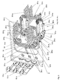
- the illustrated apparatus for forming and passing blister stacks comprises two bearing plates 2, which form a gap between them, in which three circumferential transfer units 4a, 4b, 4c are arranged.
- the transfer units 4a, 4b, 4c receive blister packs 6 which are transported by a feed device (not shown) and deliver blister stacks 7 obtained by stacking these blister packs 6 to a transport device 8, which further conveys the blister stacks 7 for further processing.
- the blister packs 6 are in this case preferably supplied to the device for forming and transferring blister stacks by means of the feed device, not shown, from above, usually individually and at predetermined time intervals.
- Such feeders are well known.
- suction belts can be used, on which the blister packs 6 are transported suspended.
- the transport device 8 for the further transport of the formed blister stacks 7 behind the device according to the invention for the formation and transfer of blister stacks is usually a circulating product transport chain of a cartoning machine, in which the blister stacks 7 formed are inserted into corresponding cartons.
- the transport device 8 has a plurality of driver units 9, also called cell angles, which define the individual compartments of the transport device 8.
- these driver units 9 are comb-shaped and protrude outwardly from a revolving chain 11 and a belt.
- the device for forming and transferring blister stacks comprises three independent drive units 10a, 10b, 10c, which independently control the three transfer units 4a, 4b, 4c.
- each transfer unit 4a, 4b, 4c two transport belts 12a, 12b, 12c, which are arranged parallel to each other and spaced from each other.
- the two inner transport belts 12a are driven by the first drive unit 10a
- the two middle transport belts 12b are driven by the second drive unit 10b
- the two outer transport belts 12c are driven by the third drive unit 10c.
- All transport belts 12a, 12b, 12c show a substantially quadrangular course and run parallel to one another.
- a diverting pulley 14a, 14b, 14c for each transporting belt 12a, 12b, 12c, in the preferred embodiment only one of the diverting pulleys 14a, 14b, 14c for each Transport belt 12a, 12b, 12c of the respective drive unit 10a, 10b, 10c is driven, while the other three guide rollers 14a, 14b, 14c of the respective conveyor belt 12a, 12b, 12c only run along.
- the deflection rollers 14a, 14b, 14c are designed as toothed belt wheels and the transport belts 12a, 12b, 12c as a toothed belt.
- the power transmission from the drive units 10a, 10b, 10c to the deflection rollers 14a, 14b, 14c takes place in the illustrated example via transmission belts 16a, 16b, 16c and a corresponding nested arrangement of shafts 18a, 18b, 18c (FIG. Fig. 3 ) of the deflection rollers 14a, 14b, 14c.
- the shaft 18a is formed for the two inner pulleys 14a as a solid shaft, while the other two pairs of pulleys 14b, 14c are driven by two shafts 18b, 18c, which are formed as hollow shafts. All shafts 18a, 18b, 18c are rotatable independently of each other.
- Each transfer unit 4a, 4b, 4c has, in addition to the two transport belts 12a, 12b, 12c, in each case two carrier elements 20a, 20b, 20c, which are offset relative to one another and are rotatably attached to the respective transport belt 12a, 12b, 12c. More specifically, the two driving elements 20a are attached to the transporting belt 12a, the driving elements 20b are attached to the transporting belt 12b and the driving elements 20c are attached to the transporting belt 12c. Based on the circulation of the associated transfer unit 4a, 4b, 4c, the two carrier elements 20a, 20b, 20c of each transfer unit 4a, 4b, 4c are each preferably arranged exactly opposite one another, ie offset by 180 °.
- the driving elements 20a, 20b, 20c are preferably rectilinear and flat and, in a preferred embodiment, comb-shaped.
- each driving element 20a, 20b, 20c has a first end horizontally extending rod 22a, 22b, 22c, which is rotatably mounted in a respectively attached to the corresponding transport belt 12a, 12b, 12c receiving member 24a, 24b, 24c.
- the receiving elements 24a, 24b, 24c for example, from the conveyor belt 12a, 12b, 12c outwardly projecting pins with corresponding bearing bushes for the rods 22a, 22b, 22c.
- Each rod 22a, 22b, 22c is connected to an angled guide lever 26a, 26b, 26c which has two cam rollers 28a, 28b, 28c on its two legs.
- the two cam rollers 28a, 28b, 28c of a guide lever are guided in two mutually offset guide grooves 30, 32 in one of the bearing plates 2 of the device.
- the guide grooves 30, 32 preferably show the same course.
- the other bearing plate 2 has identical guide grooves 30, 32.
- successive carrier elements 20a, 20b, 20c of different transfer units 4a, 4b, 4c have their guide levers 26a, 26b, 26c respectively on different sides of the corresponding bar 22a, 22b, 22c and thus the cam rollers 28a, 28b, 28c successively Carrier elements 20a, 20b, 20c also alternately in the guide grooves 30, 32 of a bearing plate 2 and the opposite bearing plate 2 are guided.
- mutual obstruction of the guide levers 26a, 26b, 26c or cam rollers 28a, 28b, 28c is also possible in closely adjacent driving elements 20a, 20b, 20c.
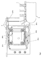
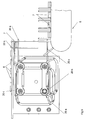
- each entraining element 20a, 20b, 20c is forcibly guided in such a way that at least in a transfer area between a blister receiving position (see the position of the entrainment element 20a on the top right in FIG Fig. 4 ) and a blister dispensing position located below the blister receiving position (see the position of the follower 20a at the bottom right in FIG Fig. 7 ) shows a horizontal orientation.
- the drive units 10a, 10b, 10c are driven in such a way that there are always two carrier elements 20a, 20b, 20c of two different transfer units 4a, 4b, 4c each move at a predetermined distance from each other from the blister receiving position to the blister dispensing position (preferably only vertically) and thus keep the blister stack 7 clamped in the transfer area from above and below.
- the guidance of the blister stacks 7 in the transfer region can additionally be supported by vertically extending, fixed guide rods 34.
- the three drive units 10a, 10b, 10c are controlled in such a way that, while the two carrier elements 20a, 20b, 20c of two different transfer units 4a, 4b, 4c move from the blister receiving position to the blister dispensing position at a predetermined distance from each other, a carrier element 20a, 20b , 20c of the remaining third transfer unit 4a, 4b, 4c moves to the blister receiving position.
- a carrier element 20a, 20b , 20c of the remaining third transfer unit 4a, 4b, 4c moves to the blister receiving position.
- new blister packs 6 can already be stacked in the device during the transfer movement of the previous blister stack 7.
- the driving element 20a is arranged at the top right in a blister receiving position. In this position, it serves as a support for the blister packs 6 to be stacked, which are brought from above through the feed device, not shown. Ideally, the entrainment member 20a moves downwardly as the blister stack 7 is filled to ensure the gradual filling of the apparatus. If now, as in Fig. 5 shown, a blister stack 7 of desired height is formed on the driving element 20a, the blister stack 7 is covered by the driving element 20b right above and the blister stack 7 thus clamped between the two driving elements 20a and 20b.
Landscapes
- Engineering & Computer Science (AREA)
- Mechanical Engineering (AREA)
Claims (10)
- Dispositif pour former et acheminer des piles de blisters (7), comprenant
au moins une unité de transfert rotative (4a, 4b, 4c), chaque unité de transfert (4a, 4b, 4c) présentant au moins une courroie de transport (12a, 12b, 12c), sur laquelle sont respectivement fixés tournants et en déport mutuel deux éléments d'entraînement (20a, 20b, 20c) ;
chaque élément d'entraînement (20a, 20b, 20c) étant à guidage forcé de telle sorte qu'il présente une orientation horizontale au moins dans une zone de transfert entre une position de réception des blisters et une position de distribution des blisters sous-jacente à la position de réception ;
caractérisé en ce que
le dispositif présente trois unités d'entraînement (10a, 10b, 10c) indépendantes ;
le dispositif présente trois unités de transfert rotatives (4a, 4b, 4c), chacune des trois unités de transfert (4a, 4b, 4c) étant commandée indépendamment l'une de l'autre par respectivement l'une des trois unités d'entraînement (10a, 10b, 10c) ; et
que les unités d'entraînement (10a, 10b, 10c) sont commandées de telle sorte que deux éléments d'entraînement (20a, 20b, 20c) de deux unités de transfert différentes (4a, 4b, 4c) se déplacent respectivement à une distance mutuelle prédéfinie de la position de réception à la position de distribution des blisters et coincent ainsi entre eux, à partir du haut et du bas, la pile de blisters (7) dans la zone de transfert. - Dispositif selon la revendication 1, caractérisé en ce que chaque unité de transfert (4a, 4b, 4c) présente deux courroies de transport (12a, 12b, 12c), qui sont disposées parallèlement entre elles et à distance les unes des autres.
- Dispositif selon l'une des revendications 1 et 2, caractérisé en ce que chaque élément d'entraînement (20a, 20b, 20c) est configuré en forme de peigne.
- Dispositif selon l'une des revendications précédentes, caractérisé en ce que chaque élément d'entraînement (20a, 20b, 20c) présente à une première extrémité une tige horizontale (22a, 22b, 22c), logée tournante dans un élément de réception (24a, 24b, 24c) fixé sur la courroie de transport (12a, 12b, 12c) correspondante.
- Dispositif selon la revendication 4, caractérisé en ce que la tige (22a, 22b, 22c) est assemblée avec un levier de guidage angulaire (26a, 26b, 26c), qui présente sur ses deux branches deux galets de came (28a, 28b, 28c), guidés dans deux rainures de guidage (30, 32) d'une plaque support (2) du dispositif.
- Dispositif selon l'une des revendications précédentes, caractérisé en ce que les courroies de transport (12a, 12b, 12c) de chaque unité de transfert (4a, 4b, 4c) sont parallèles entre elles et présentent une allure essentiellement quadrangulaire, une poulie de renvoi (14a, 14b, 14c) pour chaque courroie de transport (12a, 12b, 12c) étant disposée dans chaque angle du quadrilatère.
- Dispositif selon la revendication 6, caractérisé en ce que les courroies de transport (12a, 12b, 12c) sont réalisées sous forme de courroies dentées, et que les poulies de renvoi (14a, 14b, 14c) sont réalisées sous forme de pignons de courroies dentées.
- Dispositif selon l'une des revendications précédentes, caractérisé en ce que l'une des poulies de renvoi (14a, 14b, 14c) pour chaque courroie de transport (12a, 12b, 12c) est entrainée par l'unité d'entraînement respective (10a, 10b, 10c).
- Dispositif selon l'une des revendications précédentes, caractérisé en ce que les trois unités d'entraînement (10a, 10b, 10c) sont des servomoteurs.
- Dispositif selon l'une des revendications précédentes, caractérisé en ce que les trois unités d'entraînement (10a, 10b, 10c) sont commandées de telle sorte que, pendant que deux éléments d'entraînement (20a, 20b, 20c) de deux unités de transfert différentes (4a, 4b, 4c) se déplacent à une distance mutuelle prédéfinie de la position de réception à la position de distribution des blisters, un élément d'entraînement (20a, 20b, 20c) de la troisième unité de transfert restante (4a, 4b, 4c) se déplace dans la position de réception des blisters.
Priority Applications (2)
| Application Number | Priority Date | Filing Date | Title |
|---|---|---|---|
| EP12175745.4A EP2684823B1 (fr) | 2012-07-10 | 2012-07-10 | Dispositif de formation et de transfert de piles d'emballages blister |
| US13/934,387 US20140017057A1 (en) | 2012-07-10 | 2013-07-03 | Device for forming and passing on stacks of blister packs |
Applications Claiming Priority (1)
| Application Number | Priority Date | Filing Date | Title |
|---|---|---|---|
| EP12175745.4A EP2684823B1 (fr) | 2012-07-10 | 2012-07-10 | Dispositif de formation et de transfert de piles d'emballages blister |
Publications (2)
| Publication Number | Publication Date |
|---|---|
| EP2684823A1 EP2684823A1 (fr) | 2014-01-15 |
| EP2684823B1 true EP2684823B1 (fr) | 2014-09-03 |
Family
ID=46466325
Family Applications (1)
| Application Number | Title | Priority Date | Filing Date |
|---|---|---|---|
| EP12175745.4A Not-in-force EP2684823B1 (fr) | 2012-07-10 | 2012-07-10 | Dispositif de formation et de transfert de piles d'emballages blister |
Country Status (2)
| Country | Link |
|---|---|
| US (1) | US20140017057A1 (fr) |
| EP (1) | EP2684823B1 (fr) |
Families Citing this family (2)
| Publication number | Priority date | Publication date | Assignee | Title |
|---|---|---|---|---|
| CH714401A1 (de) * | 2017-12-04 | 2019-06-14 | Ferag Ag | Vorrichtung zum Beladen und Entladen von schienengeführten Hängefördersystemen. |
| US12545524B2 (en) | 2023-12-18 | 2026-02-10 | Lewco, Inc. | Vertical conveying system |
Family Cites Families (12)
| Publication number | Priority date | Publication date | Assignee | Title |
|---|---|---|---|---|
| US3479932A (en) * | 1968-03-14 | 1969-11-25 | Ind Dev Ab | Bucket drive |
| US4399905A (en) * | 1981-07-02 | 1983-08-23 | The Procter & Gamble Company | Apparatus for alternately forming and forwarding stacks of articles |
| US4577853A (en) * | 1984-01-16 | 1986-03-25 | Harris Graphics Corporation | Stacking apparatus |
| US4599025A (en) * | 1984-04-16 | 1986-07-08 | Oscar Mayer Foods Corporation | Stacker assembly |
| DE3708604A1 (de) * | 1987-03-17 | 1988-09-29 | Hoefliger Harro Verpackung | Verfahren und vorrichtung zum gruppenweise sammeln und verpacken von flachbeutelpackungen |
| JPH0767971B2 (ja) * | 1992-06-23 | 1995-07-26 | 忠男 宇野 | 立体形シートブロック集積装置 |
| US5772391A (en) * | 1995-11-22 | 1998-06-30 | Quipp Systems, Inc. | Stacker for counting and stacking signatures delivered by a gripper conveyor |
| IT1285453B1 (it) * | 1996-01-25 | 1998-06-08 | Ima Spa | Metodo ed apparecchiatura per il prelievo e l'impilaggio di prodotti alimentari in file multiple e per il convogliamento delle pile di |
| US7470102B2 (en) * | 2001-07-27 | 2008-12-30 | C.G. Bretting Manufacturing Co., Inc. | Apparatus and method for insertion of separating means into a forming stack of sheets discharged from a starwheel assembly |
| US6679491B2 (en) * | 2001-09-17 | 2004-01-20 | Siemens Aktiengesellschaft | Mail piece feeder control system and method |
| ITBO20010713A1 (it) * | 2001-11-23 | 2003-05-23 | Marchesini Group Spa | Metodo e dispositivo per il trasferimento di articoli , in particolare confezioni blister , alla linea di alimentazione di una macchina conf |
| US7361130B2 (en) * | 2005-05-03 | 2008-04-22 | Windmoeller And Hoelscher | System for production and subsequent palletizing of tube segments, bags or sacks |
-
2012
- 2012-07-10 EP EP12175745.4A patent/EP2684823B1/fr not_active Not-in-force
-
2013
- 2013-07-03 US US13/934,387 patent/US20140017057A1/en not_active Abandoned
Also Published As
| Publication number | Publication date |
|---|---|
| EP2684823A1 (fr) | 2014-01-15 |
| US20140017057A1 (en) | 2014-01-16 |
Similar Documents
| Publication | Publication Date | Title |
|---|---|---|
| EP2792626B1 (fr) | Procédé et dispositif de regroupement | |
| EP0298294B1 (fr) | Dispositif pour le groupement de paquets | |
| DE4100769C2 (de) | Vorrichtung zum Fördern von Produkten in einer Verpackungsmaschine | |
| DE102016207157A1 (de) | Eine beutelstapeleinrichtung | |
| DE202016009214U1 (de) | Vorrichtung zur Versorgung eines Zwischenförderers | |
| EP3153025B1 (fr) | Dispositif destine au traitement individuel de saucisse | |
| WO2016156415A1 (fr) | Dispositif tampon | |
| EP3034414A1 (fr) | Procédé de transfert de produit d'emballage dans des récipients et de transport des récipients remplis | |
| DE1802760A1 (de) | Stapelvorrichtung fuer Druckwerke,insbesondere Zeitungen | |
| EP2865618B1 (fr) | Dispositif pour transférer des piles d' emballages blister | |
| EP2939963B1 (fr) | Dispositif d'alimentation destiné à alimenter en sacs remplis un dispositif de palettisation | |
| EP0656309A1 (fr) | Dispositif pour constituer des colis de papiers-valeur à partir de liasses de papiers valeur | |
| EP2361865B1 (fr) | Procédé et dispositif de formation de piles à partir d'un flux de produits d'impression en formation imbriquée | |
| EP2684823B1 (fr) | Dispositif de formation et de transfert de piles d'emballages blister | |
| EP3025994B1 (fr) | Dispositif et procédé de fabrication de paquets empilés de feuilles imprimées | |
| EP3642118B1 (fr) | Poste d'orientation d' oeufs servant à orienter des oeufs et dispositif de transport et de conditionnement d' oeufs | |
| EP2133293B1 (fr) | Dispositif de transmission de marchandises sur un système de transport de marchandises ou sur un dispositif de stockage | |
| WO2019063165A1 (fr) | Répartiteur de lignes doté de moteurs linéaires | |
| EP0273859A2 (fr) | Dispositif pour distribuer des produits sous forme de disque | |
| CH673818A5 (fr) | ||
| EP0526403A1 (fr) | Procédé et dispositif pour la fabrication de groupes de disques alimentaires | |
| CH443114A (de) | F¦rdervorrichtung für Kartoniermaschinen oder andere Verpackungsmaschinen | |
| EP0822739B1 (fr) | Appareil automatisé de test de cartes de circuit électronique | |
| DE202014002777U1 (de) | Hochgeschwindigkeits-Produktstapelkasten zum automatischen Zählen und Stapeln von einlaufenden Produkten und zum Weitertransport der Produktstapel in einem Fächerband bei hoher Einlaufgeschwindigkeit der Produkte | |
| DE3901201A1 (de) | Ketten-speichervorrichtung |
Legal Events
| Date | Code | Title | Description |
|---|---|---|---|
| PUAI | Public reference made under article 153(3) epc to a published international application that has entered the european phase |
Free format text: ORIGINAL CODE: 0009012 |
|
| AK | Designated contracting states |
Kind code of ref document: A1 Designated state(s): AL AT BE BG CH CY CZ DE DK EE ES FI FR GB GR HR HU IE IS IT LI LT LU LV MC MK MT NL NO PL PT RO RS SE SI SK SM TR |
|
| AX | Request for extension of the european patent |
Extension state: BA ME |
|
| 17P | Request for examination filed |
Effective date: 20140317 |
|
| RBV | Designated contracting states (corrected) |
Designated state(s): AL AT BE BG CH CY CZ DE DK EE ES FI FR GB GR HR HU IE IS IT LI LT LU LV MC MK MT NL NO PL PT RO RS SE SI SK SM TR |
|
| GRAP | Despatch of communication of intention to grant a patent |
Free format text: ORIGINAL CODE: EPIDOSNIGR1 |
|
| INTG | Intention to grant announced |
Effective date: 20140606 |
|
| GRAS | Grant fee paid |
Free format text: ORIGINAL CODE: EPIDOSNIGR3 |
|
| GRAA | (expected) grant |
Free format text: ORIGINAL CODE: 0009210 |
|
| AK | Designated contracting states |
Kind code of ref document: B1 Designated state(s): AL AT BE BG CH CY CZ DE DK EE ES FI FR GB GR HR HU IE IS IT LI LT LU LV MC MK MT NL NO PL PT RO RS SE SI SK SM TR |
|
| REG | Reference to a national code |
Ref country code: GB Ref legal event code: FG4D Free format text: NOT ENGLISH |
|
| REG | Reference to a national code |
Ref country code: AT Ref legal event code: REF Ref document number: 685459 Country of ref document: AT Kind code of ref document: T Effective date: 20140915 Ref country code: CH Ref legal event code: EP |
|
| REG | Reference to a national code |
Ref country code: IE Ref legal event code: FG4D Free format text: LANGUAGE OF EP DOCUMENT: GERMAN |
|
| REG | Reference to a national code |
Ref country code: DE Ref legal event code: R096 Ref document number: 502012001191 Country of ref document: DE Effective date: 20141016 |
|
| PG25 | Lapsed in a contracting state [announced via postgrant information from national office to epo] |
Ref country code: LT Free format text: LAPSE BECAUSE OF FAILURE TO SUBMIT A TRANSLATION OF THE DESCRIPTION OR TO PAY THE FEE WITHIN THE PRESCRIBED TIME-LIMIT Effective date: 20140903 Ref country code: FI Free format text: LAPSE BECAUSE OF FAILURE TO SUBMIT A TRANSLATION OF THE DESCRIPTION OR TO PAY THE FEE WITHIN THE PRESCRIBED TIME-LIMIT Effective date: 20140903 Ref country code: NO Free format text: LAPSE BECAUSE OF FAILURE TO SUBMIT A TRANSLATION OF THE DESCRIPTION OR TO PAY THE FEE WITHIN THE PRESCRIBED TIME-LIMIT Effective date: 20141203 Ref country code: GR Free format text: LAPSE BECAUSE OF FAILURE TO SUBMIT A TRANSLATION OF THE DESCRIPTION OR TO PAY THE FEE WITHIN THE PRESCRIBED TIME-LIMIT Effective date: 20141204 Ref country code: ES Free format text: LAPSE BECAUSE OF FAILURE TO SUBMIT A TRANSLATION OF THE DESCRIPTION OR TO PAY THE FEE WITHIN THE PRESCRIBED TIME-LIMIT Effective date: 20140903 Ref country code: SE Free format text: LAPSE BECAUSE OF FAILURE TO SUBMIT A TRANSLATION OF THE DESCRIPTION OR TO PAY THE FEE WITHIN THE PRESCRIBED TIME-LIMIT Effective date: 20140903 |
|
| REG | Reference to a national code |
Ref country code: NL Ref legal event code: VDEP Effective date: 20140903 |
|
| REG | Reference to a national code |
Ref country code: LT Ref legal event code: MG4D |
|
| PG25 | Lapsed in a contracting state [announced via postgrant information from national office to epo] |
Ref country code: RS Free format text: LAPSE BECAUSE OF FAILURE TO SUBMIT A TRANSLATION OF THE DESCRIPTION OR TO PAY THE FEE WITHIN THE PRESCRIBED TIME-LIMIT Effective date: 20140903 Ref country code: HR Free format text: LAPSE BECAUSE OF FAILURE TO SUBMIT A TRANSLATION OF THE DESCRIPTION OR TO PAY THE FEE WITHIN THE PRESCRIBED TIME-LIMIT Effective date: 20140903 Ref country code: CY Free format text: LAPSE BECAUSE OF FAILURE TO SUBMIT A TRANSLATION OF THE DESCRIPTION OR TO PAY THE FEE WITHIN THE PRESCRIBED TIME-LIMIT Effective date: 20140903 Ref country code: LV Free format text: LAPSE BECAUSE OF FAILURE TO SUBMIT A TRANSLATION OF THE DESCRIPTION OR TO PAY THE FEE WITHIN THE PRESCRIBED TIME-LIMIT Effective date: 20140903 |
|
| PG25 | Lapsed in a contracting state [announced via postgrant information from national office to epo] |
Ref country code: NL Free format text: LAPSE BECAUSE OF FAILURE TO SUBMIT A TRANSLATION OF THE DESCRIPTION OR TO PAY THE FEE WITHIN THE PRESCRIBED TIME-LIMIT Effective date: 20140903 |
|
| PG25 | Lapsed in a contracting state [announced via postgrant information from national office to epo] |
Ref country code: CZ Free format text: LAPSE BECAUSE OF FAILURE TO SUBMIT A TRANSLATION OF THE DESCRIPTION OR TO PAY THE FEE WITHIN THE PRESCRIBED TIME-LIMIT Effective date: 20140903 Ref country code: IS Free format text: LAPSE BECAUSE OF FAILURE TO SUBMIT A TRANSLATION OF THE DESCRIPTION OR TO PAY THE FEE WITHIN THE PRESCRIBED TIME-LIMIT Effective date: 20150103 Ref country code: PT Free format text: LAPSE BECAUSE OF FAILURE TO SUBMIT A TRANSLATION OF THE DESCRIPTION OR TO PAY THE FEE WITHIN THE PRESCRIBED TIME-LIMIT Effective date: 20150105 Ref country code: EE Free format text: LAPSE BECAUSE OF FAILURE TO SUBMIT A TRANSLATION OF THE DESCRIPTION OR TO PAY THE FEE WITHIN THE PRESCRIBED TIME-LIMIT Effective date: 20140903 Ref country code: SK Free format text: LAPSE BECAUSE OF FAILURE TO SUBMIT A TRANSLATION OF THE DESCRIPTION OR TO PAY THE FEE WITHIN THE PRESCRIBED TIME-LIMIT Effective date: 20140903 Ref country code: RO Free format text: LAPSE BECAUSE OF FAILURE TO SUBMIT A TRANSLATION OF THE DESCRIPTION OR TO PAY THE FEE WITHIN THE PRESCRIBED TIME-LIMIT Effective date: 20140903 |
|
| PG25 | Lapsed in a contracting state [announced via postgrant information from national office to epo] |
Ref country code: PL Free format text: LAPSE BECAUSE OF FAILURE TO SUBMIT A TRANSLATION OF THE DESCRIPTION OR TO PAY THE FEE WITHIN THE PRESCRIBED TIME-LIMIT Effective date: 20140903 |
|
| REG | Reference to a national code |
Ref country code: DE Ref legal event code: R097 Ref document number: 502012001191 Country of ref document: DE |
|
| PLBE | No opposition filed within time limit |
Free format text: ORIGINAL CODE: 0009261 |
|
| STAA | Information on the status of an ep patent application or granted ep patent |
Free format text: STATUS: NO OPPOSITION FILED WITHIN TIME LIMIT |
|
| PG25 | Lapsed in a contracting state [announced via postgrant information from national office to epo] |
Ref country code: DK Free format text: LAPSE BECAUSE OF FAILURE TO SUBMIT A TRANSLATION OF THE DESCRIPTION OR TO PAY THE FEE WITHIN THE PRESCRIBED TIME-LIMIT Effective date: 20140903 |
|
| 26N | No opposition filed |
Effective date: 20150604 |
|
| PG25 | Lapsed in a contracting state [announced via postgrant information from national office to epo] |
Ref country code: SI Free format text: LAPSE BECAUSE OF FAILURE TO SUBMIT A TRANSLATION OF THE DESCRIPTION OR TO PAY THE FEE WITHIN THE PRESCRIBED TIME-LIMIT Effective date: 20140903 |
|
| PGFP | Annual fee paid to national office [announced via postgrant information from national office to epo] |
Ref country code: IT Payment date: 20150731 Year of fee payment: 4 |
|
| REG | Reference to a national code |
Ref country code: DE Ref legal event code: R119 Ref document number: 502012001191 Country of ref document: DE |
|
| PG25 | Lapsed in a contracting state [announced via postgrant information from national office to epo] |
Ref country code: MC Free format text: LAPSE BECAUSE OF FAILURE TO SUBMIT A TRANSLATION OF THE DESCRIPTION OR TO PAY THE FEE WITHIN THE PRESCRIBED TIME-LIMIT Effective date: 20140903 |
|
| REG | Reference to a national code |
Ref country code: CH Ref legal event code: PL |
|
| PG25 | Lapsed in a contracting state [announced via postgrant information from national office to epo] |
Ref country code: LU Free format text: LAPSE BECAUSE OF FAILURE TO SUBMIT A TRANSLATION OF THE DESCRIPTION OR TO PAY THE FEE WITHIN THE PRESCRIBED TIME-LIMIT Effective date: 20150710 |
|
| REG | Reference to a national code |
Ref country code: IE Ref legal event code: MM4A |
|
| PG25 | Lapsed in a contracting state [announced via postgrant information from national office to epo] |
Ref country code: DE Free format text: LAPSE BECAUSE OF NON-PAYMENT OF DUE FEES Effective date: 20160202 Ref country code: CH Free format text: LAPSE BECAUSE OF NON-PAYMENT OF DUE FEES Effective date: 20150731 Ref country code: LI Free format text: LAPSE BECAUSE OF NON-PAYMENT OF DUE FEES Effective date: 20150731 |
|
| REG | Reference to a national code |
Ref country code: FR Ref legal event code: ST Effective date: 20160331 |
|
| PG25 | Lapsed in a contracting state [announced via postgrant information from national office to epo] |
Ref country code: FR Free format text: LAPSE BECAUSE OF NON-PAYMENT OF DUE FEES Effective date: 20150731 |
|
| PG25 | Lapsed in a contracting state [announced via postgrant information from national office to epo] |
Ref country code: IE Free format text: LAPSE BECAUSE OF NON-PAYMENT OF DUE FEES Effective date: 20150710 |
|
| GBPC | Gb: european patent ceased through non-payment of renewal fee |
Effective date: 20160710 |
|
| PG25 | Lapsed in a contracting state [announced via postgrant information from national office to epo] |
Ref country code: MT Free format text: LAPSE BECAUSE OF FAILURE TO SUBMIT A TRANSLATION OF THE DESCRIPTION OR TO PAY THE FEE WITHIN THE PRESCRIBED TIME-LIMIT Effective date: 20140903 |
|
| PG25 | Lapsed in a contracting state [announced via postgrant information from national office to epo] |
Ref country code: SM Free format text: LAPSE BECAUSE OF FAILURE TO SUBMIT A TRANSLATION OF THE DESCRIPTION OR TO PAY THE FEE WITHIN THE PRESCRIBED TIME-LIMIT Effective date: 20140903 Ref country code: HU Free format text: LAPSE BECAUSE OF FAILURE TO SUBMIT A TRANSLATION OF THE DESCRIPTION OR TO PAY THE FEE WITHIN THE PRESCRIBED TIME-LIMIT; INVALID AB INITIO Effective date: 20120710 Ref country code: BG Free format text: LAPSE BECAUSE OF FAILURE TO SUBMIT A TRANSLATION OF THE DESCRIPTION OR TO PAY THE FEE WITHIN THE PRESCRIBED TIME-LIMIT Effective date: 20140903 Ref country code: GB Free format text: LAPSE BECAUSE OF NON-PAYMENT OF DUE FEES Effective date: 20160710 |
|
| PG25 | Lapsed in a contracting state [announced via postgrant information from national office to epo] |
Ref country code: BE Free format text: LAPSE BECAUSE OF NON-PAYMENT OF DUE FEES Effective date: 20150731 |
|
| PG25 | Lapsed in a contracting state [announced via postgrant information from national office to epo] |
Ref country code: IT Free format text: LAPSE BECAUSE OF NON-PAYMENT OF DUE FEES Effective date: 20160710 |
|
| PG25 | Lapsed in a contracting state [announced via postgrant information from national office to epo] |
Ref country code: TR Free format text: LAPSE BECAUSE OF FAILURE TO SUBMIT A TRANSLATION OF THE DESCRIPTION OR TO PAY THE FEE WITHIN THE PRESCRIBED TIME-LIMIT Effective date: 20140903 Ref country code: MK Free format text: LAPSE BECAUSE OF FAILURE TO SUBMIT A TRANSLATION OF THE DESCRIPTION OR TO PAY THE FEE WITHIN THE PRESCRIBED TIME-LIMIT Effective date: 20140903 |
|
| REG | Reference to a national code |
Ref country code: AT Ref legal event code: MM01 Ref document number: 685459 Country of ref document: AT Kind code of ref document: T Effective date: 20170710 |
|
| PG25 | Lapsed in a contracting state [announced via postgrant information from national office to epo] |
Ref country code: AL Free format text: LAPSE BECAUSE OF FAILURE TO SUBMIT A TRANSLATION OF THE DESCRIPTION OR TO PAY THE FEE WITHIN THE PRESCRIBED TIME-LIMIT Effective date: 20140903 |
|
| PG25 | Lapsed in a contracting state [announced via postgrant information from national office to epo] |
Ref country code: AT Free format text: LAPSE BECAUSE OF NON-PAYMENT OF DUE FEES Effective date: 20170710 |