EP2684826A9 - Dispositif d'enroulement de fil - Google Patents
Dispositif d'enroulement de fil Download PDFInfo
- Publication number
- EP2684826A9 EP2684826A9 EP12757986.0A EP12757986A EP2684826A9 EP 2684826 A9 EP2684826 A9 EP 2684826A9 EP 12757986 A EP12757986 A EP 12757986A EP 2684826 A9 EP2684826 A9 EP 2684826A9
- Authority
- EP
- European Patent Office
- Prior art keywords
- yarn
- accumulating
- winding
- wound
- unwinding
- Prior art date
- Legal status (The legal status is an assumption and is not a legal conclusion. Google has not performed a legal analysis and makes no representation as to the accuracy of the status listed.)
- Withdrawn
Links
- 238000004804 winding Methods 0.000 title claims abstract description 110
- 230000007547 defect Effects 0.000 claims abstract description 21
- 238000009987 spinning Methods 0.000 claims abstract description 5
- 238000009825 accumulation Methods 0.000 claims description 33
- 238000001514 detection method Methods 0.000 claims description 15
- 238000010276 construction Methods 0.000 description 16
- 230000000694 effects Effects 0.000 description 6
- 230000002093 peripheral effect Effects 0.000 description 6
- 238000011144 upstream manufacturing Methods 0.000 description 6
- 238000004018 waxing Methods 0.000 description 2
Images



Classifications
-
- B—PERFORMING OPERATIONS; TRANSPORTING
- B65—CONVEYING; PACKING; STORING; HANDLING THIN OR FILAMENTARY MATERIAL
- B65H—HANDLING THIN OR FILAMENTARY MATERIAL, e.g. SHEETS, WEBS, CABLES
- B65H51/00—Forwarding filamentary material
- B65H51/20—Devices for temporarily storing filamentary material during forwarding, e.g. for buffer storage
-
- B—PERFORMING OPERATIONS; TRANSPORTING
- B65—CONVEYING; PACKING; STORING; HANDLING THIN OR FILAMENTARY MATERIAL
- B65H—HANDLING THIN OR FILAMENTARY MATERIAL, e.g. SHEETS, WEBS, CABLES
- B65H51/00—Forwarding filamentary material
- B65H51/20—Devices for temporarily storing filamentary material during forwarding, e.g. for buffer storage
- B65H51/22—Reels or cages, e.g. cylindrical, with storing and forwarding surfaces provided by rollers or bars
-
- B—PERFORMING OPERATIONS; TRANSPORTING
- B65—CONVEYING; PACKING; STORING; HANDLING THIN OR FILAMENTARY MATERIAL
- B65H—HANDLING THIN OR FILAMENTARY MATERIAL, e.g. SHEETS, WEBS, CABLES
- B65H67/00—Replacing or removing cores, receptacles, or completed packages at paying-out, winding, or depositing stations
- B65H67/08—Automatic end-finding and material-interconnecting arrangements
- B65H67/081—Automatic end-finding and material-interconnecting arrangements acting after interruption of the winding process, e.g. yarn breakage, yarn cut or package replacement
-
- B—PERFORMING OPERATIONS; TRANSPORTING
- B65—CONVEYING; PACKING; STORING; HANDLING THIN OR FILAMENTARY MATERIAL
- B65H—HANDLING THIN OR FILAMENTARY MATERIAL, e.g. SHEETS, WEBS, CABLES
- B65H2701/00—Handled material; Storage means
- B65H2701/30—Handled filamentary material
- B65H2701/31—Textiles threads or artificial strands of filaments
Definitions
- the present invention relates to an art of a yarn winding device.
- a yarn winding device is well known as a device which rewinds a package while eliminating threading defects of a yarn feeding bobbin around which is wound a yarn that is spun by a fine spinning machine.
- the yarn winding device provided therein with a yarn accumulating device (accumulator) is known (for example, see the Patent Document 1).
- the yarn winding device provided therein with the yarn accumulating device can continue yarn winding work without stopping a package winding device.
- the package winding device winds a yarn accumulated in the yarn accumulating device and continues the yarn winding work.
- a yarn accumulated in the yarn accumulating device is led out (a yarn end is pulled out) and introduced into a yarn splicing device, and the introduced yarn end is yarn together with a yarn end at the side of the yarn feeding bobbin.
- the yarn accumulating device when sloughing (loop cast-off) occurs in a yarn wound out from the yarn accumulating device toward a package, yarn breakage occurs and the winding of the package is stopped.
- the conventional yarn accumulating device represented by the Patent Document 1 since a yarn wound former is pushed upward by a yarn wound later, fluffs may be intertwined with each other, thereby causing sloughing at the time of unwinding of the yarn. Since the yarn wound former is pushed upward by the yarn wound later, at the time of pulling out the yarn end accumulated in the yarn accumulating device, the fluffs may be intertwined with each other, thereby causing draw-out defect.
- Patent Document 1 the Japanese Patent Laid Open Gazette 2009-242042
- the invention is a yarn winding device which rewinds a package while eliminating threading defects of a yarn feeding bobbin around which is wound a yarn that is spun by a fine spinning machine, including a yarn feeding part which supports the yarn feeding bobbin, a yarn accumulating device which winds and accumulates the yarn of the yarn feeding bobbin, a winding part which winds the yarn accumulated in the yarn accumulating part for a predetermined winding speed so as to form the package, a threading defect detection part which supervises threading defect, and a yarn splicing part which splices broken yarn ends when the yarn is broken.
- the yarn accumulating device has a yarn accumulating part accumulating the yarn and a winding part winding the yarn to the yarn accumulating part while rotating, and the yarn accumulating part has a yarn accumulating body to which the yarn is wound and a yarn conveying mechanism applying conveying power from a winding side to a unwinding side on the whole wound yarn.
- the invention is the yarn winding device according to the first aspect, wherein the yarn accumulating device has a draw-out part which sucks the yarn end wound to the yarn accumulating part when the yarn is broken.
- the invention is the yarn winding device according to the third aspect, wherein the yarn accumulating device has a yarn accumulation amount detection part which detects a accumulation amount of the yarn accumulated in the yarn accumulating device.
- the invention is the yarn winding device according to the first to fourth aspects, wherein the yarn accumulating body is a belt, and the yarn conveying mechanism is a pulley which drives the belt.
- the invention is the yarn winding device according to the first to fourth aspects, wherein the yarn conveying mechanism has a swinging member which is swung concerning the yarn accumulating body and a rotation shaft which is rotated eccentrically.
- the yarn wound to the yarn accumulating body that is, the whole yarn wound to the yarn accumulating part can be sent from the winding side toward the unwinding side of the yarn accumulating body, and the wound yarn is conveyed while maintaining equal spaces in the yarn, whereby accumulated yarn layers are not intertwined with each other. Accordingly, sloughing can be prevented.
- the yarn wound to the yarn accumulating body is sent from the winding side toward the unwinding side of the yarn accumulating part and equal spaces in the wound yarn are maintained, whereby accumulated yarn layers are not intertwined with each other. Accordingly, at the time of sucking and pulling out the yarn end wound to the yarn accumulating body, draw-out defect caused by intertwining of yarns can be prevented.
- only one yarn Y can pass through the yarn unwinding assistant part, whereby yarn breakage can be prevented.
- the yarn wound to the yarn accumulating body is sent from the winding side toward the unwinding side of the yarn accumulating part and equal spaces in the wound yarn are maintained, whereby accumulated yarn layers are not intertwined with each other. Accordingly, sloughing can be prevented.
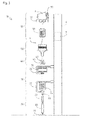
- FIG. 1 An explanation will be given on a winding unit 10 which is a first embodiment of an automatic winding device of the present invention referring to Fig. 1 .
- the winding unit 10 winds a package P while eliminating threading defects of a yarn feeding bobbin B1 around which is wound a yarn Y that is spun by a fine spinning machine.
- the winding unit 10 is arranged in parallel in a lengthwise direction of a machine bed of an automatic winder.
- the winding unit 10 has a controller 5, a frame 6, a yarn feeding part 20, a yarn splicing part 30, a threading defect detection part 40, a yarn accumulating device (accumulator) 100, and a winding part 50.
- the frame 6 supports the devices constituting the winding unit 10.
- the frame 6 supports the yarn feeding part 20, the yarn splicing part 30, the threading defect detection part 40, the yarn accumulating device 100 and the winding part 50 along a winding direction from an upstream side to a downstream side.
- the controller 5 is housed in the frame 6.
- the controller 5 is connected electrically to the devices constituting the winding unit 10.
- the controller 5 has a function for controlling the devices constituting the winding unit 10 so as to wind a package P while eliminating threading defects of a yarn feeding bobbin B1.
- the yarn feeding part 20 has a bobbin supply device (not shown), a yarn feeding bobbin holding part 21, a yarn unwinding assistant device 22, a yarn feeler 23, and a first tenser 24.
- the bobbin supply device supplies a new yarn feeding bobbin B 1 to the yarn feeding bobbin holding part 21.
- the yarn feeding bobbin holding part 21 receives and holds the yarn feeding bobbin B1 from the bobbin supply device.
- the yarn unwinding assistant device 22 assists unwinding of a yarn from the yarn feeding bobbin B1.
- the yarn feeler 23 detects that no yarn Y pulled out from the yarn feeding bobbin B1 exists.
- the first tenser 24 applies predetermined tension on a running yarn Y.
- the yarn splicing part 30 has a splicer device 31, a lower yarn guide pipe 32 and an upper yarn guide pipe 33.
- the splicer device 31 splices a yarn Y at a side of a yarn feeding bobbin B1 (lower yarn) together with a yarn Y at a side of a package P (upper yarn) at the time of detection of threading defects of a clearer 41 discussed later or at the time of yarn breakage under unwinding from the yarn feeding bobbin B1.
- the lower yarn guide pipe 32 catches and guides a lower yarn at the side of the yarn feeding bobbin B1.
- the upper yarn guide pipe 33 catches and guides an upper yarn at the side of the package P.
- the threading defect detection part 40 has the clearer 41 and a waxing device 42.
- the clearer 41 supervises thickness of a yarn Y with a suitable sensor so as to detect defects.
- the waxing device 42 applies wax on a running yarn Y
- the yarn accumulating device (accumulator) 100 accumulates a yarn Y sent from a yarn feeding bobbin B1.
- the yarn accumulating device 100 will be explained in detail later.
- the winding part 50 has a second tenser 51 and a winding drum 52.
- the second tenser 51 controls tension of a yarn Y unwound from the yarn accumulating device 100.
- the winding drum 52 makes a yarn Y traverse and rotates a winding bobbin B2.
- the yarn accumulating device 100 has a yarn unwinding assistant part 110, a yarn accumulation amount detection part 120, a yarn accumulating part 130, a winding part 140 and a draw-out part 150.
- the yarn unwinding assistant part 110 will be explained in detail later.
- the yarn accumulation amount detection part 120 has the accumulation upper limit sensor 121, the accumulation lower limit sensor 122 and the accumulation lowest limit sensor 123.
- the accumulation upper limit sensor 121, the accumulation lower limit sensor 122 and the accumulation lowest limit sensor 123 are arranged on an attachment frame (not shown) of the yarn accumulating device 100.
- the accumulation upper limit sensor 121 is arranged at a position facing an upper end of a yarn Y wound to the yarn accumulating part 130 when yarn accumulation amount of the yarn accumulating part 130 reaches the upper limit yarn accumulation amount.
- the accumulation lower limit sensor 122 is arranged at a position facing an upper end of a yarn Y wound to the yarn accumulating part 130 when the yarn accumulation amount of the yarn accumulating part 130 reaches the lower limit yarn accumulation amount.
- the accumulation lowest limit sensor 123 is arranged at a position facing an upper end of a yarn Y wound to the yarn accumulating part 130 when yarn accumulation amount of the yarn accumulating part 130 reaches the lowest limit yarn accumulation amount.
- the yarn accumulating part 130 has a winding side 130R and a unwinding side 130F.
- the winding side 130R is the lower side of the yarn accumulating part 130.
- the unwinding side 130F is the upper side of the yarn accumulating part 130.
- a yarn Y is wound from the winding side 130R, and the yarn Y is unwound from the unwinding side 130F.
- the yarn accumulating part 130 in this embodiment is arranged so that shafts thereof are in parallel to the vertical direction, the shafts may alternatively be arranged aslant concerning the vertical direction.
- the yarn accumulating part 130 will be explained in detail later.
- the winding part 140 has a winding arm 141, a balancer 142, the motor 143 and an output shaft 145.
- the winding arm 141 is extended outward and upward from the outer circumference of the output shaft 145 and is curved toward the surface of the yarn accumulating part 130.
- the winding arm 141 is formed pipe-like and formed therein with a yarn passage in which a yarn Y can run.
- the winding arm 141 is rotatable concerning the yarn accumulating part 130.
- the balancer 142 is arranged at the side facing the winding arm 141 centering on the output shaft 145 in the axial direction of the output shaft 145.
- the balancer 142 is formed integrally with the output shaft 145.
- the motor 143 makes rotate the winding arm 141, the balancer 142 and the output shaft 145.
- the output shaft 145 is formed pipe-like and formed therein with a yarn passage in which a yarn Y can run.
- the yarn passage formed in the output shaft 145 is communicated with the yarn passage formed in the winding arm 141.
- the draw-out part 150 has a blowing-down nozzle 151, the electromagnetic valve 152, the compressed air generator 153 and a connection pipe 154.
- the blowing-down nozzle 151 will be explained in detail later.
- the compressed air generator 153 generates compressed air.
- the connection pipe 154 connects the compressed air generator 153 to the blowing-down nozzle 151.
- a flow channel is formed in the connection pipe 154.
- the electromagnetic valve 152 is provided in the middle of the connection pipe 154. The function of the draw-out part 150 will be explained in detail later.
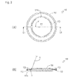
- Fig. 3(A) is a plan view of the yarn unwinding assistant part 110.
- Fig. 3(B) is an arrow sectional view of the line S1-S1 in Fig. 3(A) .
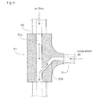
- the blowing-down nozzle 151 connects the output shaft 145 to the connection pipe 154.
- a yarn flow channel 151A and a blowing-down flow channel 151 B are formed in the blowing-down nozzle 151.
- the yarn flow channel 151 A is communicated with the yarn passage formed in the output shaft 145.
- the blowing-down flow channel 151B is communicated with the flow channel of the connection pipe 154.
- the blowing-down flow channel 151B is inclined downward, that is, directed toward the upstream side (the yarn splicing part 30 and the threading defect detection part 40), and is connected to the yarn flow channel 151 A.
- the yarn accumulating part 130 has four endless belt conveying devices 131.
- the endless belt conveying devices 131 can send a yarn Y along a yarn conveying direction from the winding side 130R toward the unwinding side 130F.
- the endless belt conveying devices 131 are arranged respectively at four corners of a rectangle in the yarn conveying direction.
- a yarn Y is wound from the winding side 130R, and the yarn Y is unwound from the unwinding side 130F.
- Each of the endless belt conveying devices 131 has a belt 132, and a driving pulley 134 and a driven pulley 133 as a yarn sending mechanism.
- the belt 132 is laid across the driving pulley 134 and the driven pulley 133 in a tensioned state.
- the belt 132 has a belt outer side 132F as a yarn accumulating body and a belt inner side 132E.
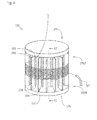
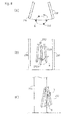
- the yarn accumulating part 230 has a yarn conveying mechanism 231 and a yarn accumulating body 236.
- the yarn conveying mechanism 231 will be explained in detail later.
- the yarn accumulating body 236 has a body 237 and a plurality of support members 238.
- the body 237 is disk-like shaped.
- the support members 238 are rectangular shaped and provided upright around the body 237 at predetermined intervals.
- the yarn conveying mechanism 231 and the yarn accumulating body 236 are arranged substantially coaxially.
- the yarn conveying mechanism 231 and the yarn accumulating body 236 are arranged so that round bars 232 of the yarn conveying mechanism 231 are arranged between the support members 238 of the yarn accumulating body 236 discussed later.
- a yarn Y is wound from a winding side 230R, and the yarn Y is unwound from a unwinding side 230F.
- Figs. 7(A) to 7(C) show a shaft 234A rotated for every 90°.
- the yarn conveying mechanism 231 has the round bars 232, a body 233, the shaft 234A, a plate 234P, an eccentric shaft 234B, an inclined shaft 234C and a motor 235.
- the body 233 is disk-like shaped, and arranged above the yarn accumulating body 236 substantially coaxially to the yarn accumulating body 236.
- the round bars 232 are provided downward around the body 233 at predetermined intervals.
- the motor 235 is arranged below the body 233 substantially eccentrically from the body 233.
- the motor 235 is connected to the controller 5.
- a swinging member of the present invention includes the round bars 232, the body 233 and the inclined shaft 234C.
- the round bars 232 and the support members 238 may alternatively be flat plates supporting a yarn Y with their surfaces.
- the shaft 234A is driven by the motor 235.
- the plate 234P is disk-like shaped.
- the center of the plate 234P is fixed to the shaft 234A.
- the eccentric shaft 234B is fixed eccentrically to the plate 234P.
- the inclined shaft 234C is inclined for a predetermined angle concerning the eccentric shaft 234B.
- the inclined shaft 234C is fixed to the eccentric shaft 234B.
- the inclined shaft 234C is slidable concerning the body 233 in the peripheral direction. On the other hand, the inclined shaft 234C cannot move concerning the body 233 in the axial direction.
- the eccentric shaft 234B is fixed eccentrically via the plate 234P. Accordingly, when the shaft 234A is rotated, the eccentric shaft 234B is rotated eccentrically.
- conveying power from the winding side 230R to the unwinding side 230F can be applied on the whole yarn wound to the support members 238 sequentially, whereby the yarn Y can be sent from the winding side 230R to the unwinding side 230F of the yarn accumulating part 230 while maintaining equal spaces among yarn layers. Accordingly, accumulated yarn layers are not intertwined with each other, whereby sloughing at the time of unwinding of a yarn caused by intertwining of fluffs does not occur. Yarn breakage does not occur when the winding part 50 unwinds a yarn Y from the yarn accumulating part 230.
Landscapes
- Engineering & Computer Science (AREA)
- Textile Engineering (AREA)
- Filamentary Materials, Packages, And Safety Devices Therefor (AREA)
- Spinning Or Twisting Of Yarns (AREA)
- Forwarding And Storing Of Filamentary Material (AREA)
Applications Claiming Priority (2)
| Application Number | Priority Date | Filing Date | Title |
|---|---|---|---|
| JP2011054281A JP2012188255A (ja) | 2011-03-11 | 2011-03-11 | 糸巻き取り装置 |
| PCT/JP2012/055929 WO2012124588A1 (fr) | 2011-03-11 | 2012-03-08 | Dispositif d'enroulement de fil |
Publications (3)
| Publication Number | Publication Date |
|---|---|
| EP2684826A1 EP2684826A1 (fr) | 2014-01-15 |
| EP2684826A9 true EP2684826A9 (fr) | 2014-04-16 |
| EP2684826A4 EP2684826A4 (fr) | 2014-07-30 |
Family
ID=46830661
Family Applications (1)
| Application Number | Title | Priority Date | Filing Date |
|---|---|---|---|
| EP12757986.0A Withdrawn EP2684826A4 (fr) | 2011-03-11 | 2012-03-08 | Dispositif d'enroulement de fil |
Country Status (4)
| Country | Link |
|---|---|
| EP (1) | EP2684826A4 (fr) |
| JP (1) | JP2012188255A (fr) |
| CN (1) | CN103429515B (fr) |
| WO (1) | WO2012124588A1 (fr) |
Families Citing this family (5)
| Publication number | Priority date | Publication date | Assignee | Title |
|---|---|---|---|---|
| JP2016044016A (ja) * | 2014-08-21 | 2016-04-04 | 村田機械株式会社 | 糸巻取装置及び自動ワインダ |
| JP2016204133A (ja) * | 2015-04-24 | 2016-12-08 | 村田機械株式会社 | 繊維機械 |
| CN109650178A (zh) * | 2019-01-28 | 2019-04-19 | 杭州方润线缆有限公司 | 线缆生产线不停机铜丝接头装置 |
| CN112279007B (zh) * | 2020-09-30 | 2022-03-22 | 铜陵顶科镀锡铜线有限公司 | 一种存储式放线张力稳定装置 |
| CN114194941B (zh) * | 2021-12-10 | 2023-12-01 | 浙江云泰纺织有限公司 | 一种自动络纱机纱线卷绕机构 |
Family Cites Families (12)
| Publication number | Priority date | Publication date | Assignee | Title |
|---|---|---|---|---|
| CH374345A (de) * | 1959-12-04 | 1963-12-31 | Sulzer Ag | Webmaschine |
| US3674057A (en) * | 1969-08-09 | 1972-07-04 | Teijin Ltd | Method and apparatus for preparing filling in shuttleless loom |
| US4026484A (en) * | 1971-06-19 | 1977-05-31 | Pavena Ag | Apparatus for controlling a winding device for a continuously supplied fiber sliver |
| JPS526379B2 (fr) * | 1971-10-09 | 1977-02-22 | ||
| DE2553892C3 (de) * | 1975-11-29 | 1979-10-04 | Skf Kugellagerfabriken Gmbh, 8720 Schweinfurt | Abzugsvorrichtung für eine Offenendspinnmaschine |
| IT8422055U1 (it) * | 1984-06-04 | 1985-12-04 | Roy Electrotex Spa | Alimentatore di trama per telai di tessitura comportante mezzi perfezionati per accumulare la riserva di trama. |
| JP3084532B2 (ja) * | 1990-07-11 | 2000-09-04 | アイ・アール・オー エー・ビー | 糸保管供給装置 |
| GB2307072B (en) * | 1994-06-10 | 1998-05-13 | Advanced Risc Mach Ltd | Interoperability with multiple instruction sets |
| DE19535747A1 (de) * | 1994-10-21 | 1996-04-25 | Barmag Barmer Maschf | Verfahren und Vorrichtung zum Tangeln eines Multifilamentfadens |
| JP4120634B2 (ja) * | 2004-11-18 | 2008-07-16 | 村田機械株式会社 | 糸測長貯留装置 |
| JP5007826B2 (ja) * | 2008-03-31 | 2012-08-22 | 村田機械株式会社 | 糸巻取装置及びこの糸巻取装置を備える自動ワインダ |
| WO2011040542A1 (fr) * | 2009-09-30 | 2011-04-07 | 村田機械株式会社 | Bobinoir de fil |
-
2011
- 2011-03-11 JP JP2011054281A patent/JP2012188255A/ja not_active Withdrawn
-
2012
- 2012-03-08 WO PCT/JP2012/055929 patent/WO2012124588A1/fr not_active Ceased
- 2012-03-08 EP EP12757986.0A patent/EP2684826A4/fr not_active Withdrawn
- 2012-03-08 CN CN201280012747.8A patent/CN103429515B/zh not_active Expired - Fee Related
Also Published As
| Publication number | Publication date |
|---|---|
| CN103429515A (zh) | 2013-12-04 |
| EP2684826A4 (fr) | 2014-07-30 |
| JP2012188255A (ja) | 2012-10-04 |
| CN103429515B (zh) | 2016-04-13 |
| WO2012124588A1 (fr) | 2012-09-20 |
| EP2684826A1 (fr) | 2014-01-15 |
Similar Documents
| Publication | Publication Date | Title |
|---|---|---|
| EP2479129B1 (fr) | Machine de renvidage de fil | |
| CN104418162B (zh) | 纤维机械 | |
| EP2441720A2 (fr) | Peigneur et appareil d'enroulement de fils l'incluant | |
| EP2684826A9 (fr) | Dispositif d'enroulement de fil | |
| CN103014942B (zh) | 纺纱机 | |
| JP2014125349A (ja) | 糸貯留装置及び紡績ユニット | |
| JP2013063839A (ja) | 糸巻取機及び糸巻取ユニット | |
| CN102574655B (zh) | 纱线卷绕装置 | |
| JP2016016957A (ja) | 糸巻取機及び糸巻取方法 | |
| EP2966200A2 (fr) | Métier à filer et procédé de filage | |
| CN103898641A (zh) | 纺纱机 | |
| EP3025996B1 (fr) | Machine d'enroulement de fil avec un dispositif d'assemblage de fil, et procédé d'assemblage de fil | |
| CN105668323B (zh) | 纱线卷绕机 | |
| CN104828649B (zh) | 纱线捕捉装置以及纱线卷取机 | |
| EP2862826A1 (fr) | Machine de renvidage de fil | |
| CN106241495B (zh) | 纱线卷取机以及纺纱机械 | |
| EP2573225A2 (fr) | Unité de filature et fileuse | |
| JP2014009052A (ja) | 繊維機械 | |
| JP4529977B2 (ja) | コアヤーン紡績機 | |
| EP3095742A1 (fr) | Machine de renvideur de fil | |
| CN104444576B (zh) | 纱线卷绕机 | |
| JP2009227413A (ja) | 糸巻取機 | |
| JP2009242041A (ja) | 糸端処理装置を有する糸条巻取機 | |
| CN112110281B (zh) | 纱线卷绕装置及包头纱形成方法 | |
| JP2013057152A (ja) | 糸巻取機 |
Legal Events
| Date | Code | Title | Description |
|---|---|---|---|
| PUAI | Public reference made under article 153(3) epc to a published international application that has entered the european phase |
Free format text: ORIGINAL CODE: 0009012 |
|
| 17P | Request for examination filed |
Effective date: 20131010 |
|
| AK | Designated contracting states |
Kind code of ref document: A1 Designated state(s): AL AT BE BG CH CY CZ DE DK EE ES FI FR GB GR HR HU IE IS IT LI LT LU LV MC MK MT NL NO PL PT RO RS SE SI SK SM TR |
|
| DAX | Request for extension of the european patent (deleted) | ||
| A4 | Supplementary search report drawn up and despatched |
Effective date: 20140630 |
|
| RIC1 | Information provided on ipc code assigned before grant |
Ipc: B65H 51/20 20060101AFI20140624BHEP Ipc: B65H 51/22 20060101ALI20140624BHEP Ipc: B65H 67/08 20060101ALI20140624BHEP |
|
| 17Q | First examination report despatched |
Effective date: 20151116 |
|
| STAA | Information on the status of an ep patent application or granted ep patent |
Free format text: STATUS: THE APPLICATION IS DEEMED TO BE WITHDRAWN |
|
| 18D | Application deemed to be withdrawn |
Effective date: 20160330 |