EP2684946A1 - Capteur pour détecter les micro-organismes et son procédé de fabrication - Google Patents
Capteur pour détecter les micro-organismes et son procédé de fabrication Download PDFInfo
- Publication number
- EP2684946A1 EP2684946A1 EP12754214.0A EP12754214A EP2684946A1 EP 2684946 A1 EP2684946 A1 EP 2684946A1 EP 12754214 A EP12754214 A EP 12754214A EP 2684946 A1 EP2684946 A1 EP 2684946A1
- Authority
- EP
- European Patent Office
- Prior art keywords
- microorganism
- polymer layer
- sensor
- electrode
- detection electrode
- Prior art date
- Legal status (The legal status is an assumption and is not a legal conclusion. Google has not performed a legal analysis and makes no representation as to the accuracy of the status listed.)
- Granted
Links
Images


Classifications
-
- C—CHEMISTRY; METALLURGY
- C12—BIOCHEMISTRY; BEER; SPIRITS; WINE; VINEGAR; MICROBIOLOGY; ENZYMOLOGY; MUTATION OR GENETIC ENGINEERING
- C12Q—MEASURING OR TESTING PROCESSES INVOLVING ENZYMES, NUCLEIC ACIDS OR MICROORGANISMS; COMPOSITIONS OR TEST PAPERS THEREFOR; PROCESSES OF PREPARING SUCH COMPOSITIONS; CONDITION-RESPONSIVE CONTROL IN MICROBIOLOGICAL OR ENZYMOLOGICAL PROCESSES
- C12Q1/00—Measuring or testing processes involving enzymes, nucleic acids or microorganisms; Compositions therefor; Processes of preparing such compositions
- C12Q1/02—Measuring or testing processes involving enzymes, nucleic acids or microorganisms; Compositions therefor; Processes of preparing such compositions involving viable microorganisms
- C12Q1/04—Determining presence or kind of microorganism; Use of selective media for testing antibiotics or bacteriocides; Compositions containing a chemical indicator therefor
-
- G—PHYSICS
- G01—MEASURING; TESTING
- G01N—INVESTIGATING OR ANALYSING MATERIALS BY DETERMINING THEIR CHEMICAL OR PHYSICAL PROPERTIES
- G01N33/00—Investigating or analysing materials by specific methods not covered by groups G01N1/00 - G01N31/00
- G01N33/48—Biological material, e.g. blood, urine; Haemocytometers
- G01N33/50—Chemical analysis of biological material, e.g. blood, urine; Testing involving biospecific ligand binding methods; Immunological testing
- G01N33/53—Immunoassay; Biospecific binding assay; Materials therefor
- G01N33/569—Immunoassay; Biospecific binding assay; Materials therefor for microorganisms, e.g. protozoa, bacteria, viruses
-
- C—CHEMISTRY; METALLURGY
- C25—ELECTROLYTIC OR ELECTROPHORETIC PROCESSES; APPARATUS THEREFOR
- C25D—PROCESSES FOR THE ELECTROLYTIC OR ELECTROPHORETIC PRODUCTION OF COATINGS; ELECTROFORMING; APPARATUS THEREFOR
- C25D5/00—Electroplating characterised by the process; Pretreatment or after-treatment of workpieces
- C25D5/60—Electroplating characterised by the structure or texture of the layers
- C25D5/605—Surface topography of the layers, e.g. rough, dendritic or nodular layers
-
- G—PHYSICS
- G01—MEASURING; TESTING
- G01N—INVESTIGATING OR ANALYSING MATERIALS BY DETERMINING THEIR CHEMICAL OR PHYSICAL PROPERTIES
- G01N33/00—Investigating or analysing materials by specific methods not covered by groups G01N1/00 - G01N31/00
- G01N33/48—Biological material, e.g. blood, urine; Haemocytometers
- G01N33/50—Chemical analysis of biological material, e.g. blood, urine; Testing involving biospecific ligand binding methods; Immunological testing
- G01N33/53—Immunoassay; Biospecific binding assay; Materials therefor
- G01N33/543—Immunoassay; Biospecific binding assay; Materials therefor with an insoluble carrier for immobilising immunochemicals
- G01N33/54366—Apparatus specially adapted for solid-phase testing
- G01N33/54373—Apparatus specially adapted for solid-phase testing involving physiochemical end-point determination, e.g. wave-guides, FETS, gratings
- G01N33/5438—Electrodes
-
- Y—GENERAL TAGGING OF NEW TECHNOLOGICAL DEVELOPMENTS; GENERAL TAGGING OF CROSS-SECTIONAL TECHNOLOGIES SPANNING OVER SEVERAL SECTIONS OF THE IPC; TECHNICAL SUBJECTS COVERED BY FORMER USPC CROSS-REFERENCE ART COLLECTIONS [XRACs] AND DIGESTS
- Y10—TECHNICAL SUBJECTS COVERED BY FORMER USPC
- Y10T—TECHNICAL SUBJECTS COVERED BY FORMER US CLASSIFICATION
- Y10T428/00—Stock material or miscellaneous articles
- Y10T428/24—Structurally defined web or sheet [e.g., overall dimension, etc.]
- Y10T428/24479—Structurally defined web or sheet [e.g., overall dimension, etc.] including variation in thickness
Definitions
- the present invention relates to a sensor for detecting microorganisms, and a method of manufacturing the sensor.
- a technique for allowing easy detection of microorganism contamination Furthermore, it is necessary in medical practice to immediately identify a disease germ causing an infectious disease. Accordingly, there is also a need for a technique by which a disease germ can be detected quickly with high sensitivity. Examples of a method of detecting/identifying microorganisms may include the ELISA method, the western blotting method and the like.
- labeled secondary antibodies are caused to further react with the antibodies (primary antibody), to monitor the chemiluminescence of the secondary antibodies and the hydrolysis reaction of ATP, thereby accomplishing detection.
- PTD 1 discloses a method of detecting a microbially-derived anion molecule (ATP, amino acid and the like) by utilizing the electrochemical properties of the polymer having a molecular mold.
- a microbially-derived anion molecule ATP, amino acid and the like
- None of the above-described methods is, however, a method of detecting a microorganism itself. Also in the ELISA method and the like, it is necessary to produce an antibody for proteins and the like specific to microorganisms, which cannot be easily done.
- An object of the present invention is to provide a novel microorganism detection sensor capable of quickly and simply detecting microorganisms with high sensitivity, and a method of manufacturing the microorganism detection sensor.
- the present invention provides a sensor comprising a detection unit including a detection electrode and a polymer layer that is disposed on the detection electrode and includes a mold having a three-dimensional structure complementary to a steric structure of a microorganism to be detected.
- the sensor detects the microorganism based on a state of capturing the microorganism in the mold.
- the polymer layer is formed by a manufacturing method including: a polymerization step of polymerizing a monomer in presence of the microorganism to be detected, to form the polymer layer having captured the microorganism on the detection electrode; a destruction step of partially destroying the microorganism captured in the polymer layer; and a peroxidation step of peroxidizing the polymer layer to release the microorganism from the polymer layer.
- the preferable embodiment of the sensor further includes a counter electrode and applies an alternating-current (AC) voltage between the detection electrode of the detection unit and the counter electrode in a state where the detection unit and the counter electrode are in contact with a sample solution, to direct the microorganism in the sample solution toward the detection unit by dielectrophoresis.
- the time period of applying the AC voltage is not particularly limited as long as the microorganism in the sample solution is directed toward the detection unit.
- the preferable embodiment of the sensor further includes a crystal oscillator having the detection electrode of the detection unit as one of electrodes, and measures a change in a mass of the polymer layer based on a change in a resonance frequency of the crystal oscillator to detect the state of capturing the microorganism.
- the monomer is preferably selected from the group consisting of pyrrole, aniline, thiophene, and derivatives thereof.
- a surface of the detection electrode on which the polymer layer is formed is preferably a roughened surface.
- the microorganism has entire electric charge or electric charge on a surface thereof that is excessively negatively charged.
- the microorganism is a bacterium.
- the destruction step includes a step of performing a bacteriolysis process.
- the bacterium may be Pseudomonas aeruginosa, Acinetobacter calcoaceticus or Escherichia coli.
- the present invention provides a method of manufacturing a sensor detecting a microorganism.
- the sensor includes a detection unit having a detection electrode and a polymer layer that is disposed on the detection electrode and includes a mold having a three-dimensional structure complementary to a steric structure of the microorganism.
- the method includes: a polymerization step of polymerizing a monomer in presence of the microorganism to be detected, to form the polymer layer having captured the microorganism on the detection electrode; a destruction step of partially destroying the microorganism captured in the polymer layer; and a step of peroxidizing the polymer layer to release the microorganism from the polymer layer.
- the senor further includes a counter electrode
- the polymerization step includes a step of applying a voltage between the detection electrode and the counter electrode that are in contact with a solution of the monomer, to electropolymerize the monomer.
- the releasing step includes a step of applying a voltage between the detection electrode and the counter electrode that are in contact with a solution within a range from neutral to alkaline, to peroxidize the polymer layer.
- the preferable embodiment of the manufacturing method includes a surface-roughening step of roughening a surface of the detection electrode on which the polymer layer is formed.
- microorganisms can be detected quickly and simply with high sensitivity. Furthermore, the method of manufacturing a sensor according to the present invention provides a sensor capable of detecting microorganisms quickly and simply with high sensitivity.
- the sensor according to the present invention includes a detection unit having a detection electrode and a polymer layer that is disposed on the detection electrode and includes a mold having a three-dimensional structure complementary to a steric structure of a microorganism.
- the sensor serves to detect the microorganism based on the state of capturing the microorganism in the mold.
- the polymer layer of the sensor according to the present invention is formed by a manufacturing method including: a polymerization step of polymerizing a monomer in the presence of a microorganism to be detected (which will be hereinafter referred to as a "target microorganism") to form a polymer layer having captured the microorganism on the detection electrode; a destruction step of partially destroying the microorganism captured in the polymer layer; and a peroxidation step of peroxidizing the polymer layer to release the microorganism from the polymer layer.
- a manufacturing method including: a polymerization step of polymerizing a monomer in the presence of a microorganism to be detected (which will be hereinafter referred to as a "target microorganism”) to form a polymer layer having captured the microorganism on the detection electrode; a destruction step of partially destroying the microorganism captured in the polymer layer; and a peroxidation step of peroxidizing the polymer layer to release the microorganism from the poly
- Fig. 1 is a cross-sectional view schematically showing a preferable step of producing a polymer layer of a sensor according to the present invention.
- Fig. 1 shows an embodiment in the case where pyrrole is used as a monomer.
- a solution 12 containing microorganisms 13 and pyrrole is prepared under the environment where it is in contact with a detection electrode 11.
- a polymerization step (St1) electrolysis is conducted using detection electrode 11 as an anode and a counter electrode (not shown) as a cathode.
- a polymer layer 14 made of polypyrrole (which is abbreviated as "PPy" in Fig. 1(b) ) is formed on detection electrode 11.
- Microorganisms 13 are captured in this formed polymer layer 14.
- Pyrrole itself contains a positive electric charge for emitting electrons to detection electrode 11 in the polymerization step. It is thus considered that, in order to make up for this positive electric charge, microorganism 13 having entire electric charge or electric charge on its surface that is excessively negatively charged is captured in polymer layer 14.
- a destruction step of partially destroying microorganism 13 captured in polymer layer 14 is performed.
- the destruction step can be performed, for example, by addition of a degrading enzyme, temperature regulation, an ultrasonic treatment, an ozone treatment, existence of residual chlorine, and a bacteriophage process.
- the destruction step can be performed by a bacteriolysis process using degrading enzymes such as lysozyme (the destruction step by the bacteriolysis process will be hereinafter also referred to as a "bacteriolysis step").
- bacteriolysis step the destruction step by the bacteriolysis process will be hereinafter also referred to as a "bacteriolysis step"
- polymer layer 14 is peroxidized in a peroxidation step (St3).
- peroxidized polypyrrole which is abbreviated as "Oppy" in Fig. 1(d)
- Oppy peroxidized polypyrrole
- microorganism 13 is released from polymer layer 14.
- the region of polymer layer 14 where microorganism 13 has existed is formed as a mold 15 having a three-dimensional structure complementary to the steric structure of microorganism 13.
- This peroxidation step (St3) also causes curing of polymer layer 14, thereby stabilizing mold 15 of microorganism 13.
- the peroxidation step (St3) is performed by adjusting solution 12 within a range from neutral to alkaline, and applying a voltage between detection electrode 11 and the counter electrode (not shown).
- a multilayer body of polymer layer 14 including mold 15 formed in this way and detection electrode 11 forms a detection unit 17 in the sensor according to the present invention.
- the three-dimensional structure of the formed mold may be different depending on the solution composition in the peroxidation reaction and the voltage for triggering the peroxidation reaction. Generally, under such a condition that the peroxidation reaction gradually advances, a mold having a closely packed three-dimensional structure is formed by microorganism 13 to be detected.
- Microorganism 13 to be detected is not particularly limited as long as it is a microorganism having entire electric charge or electric charge on its surface that is excessively negatively charged.
- Examples of microorganism 13 may be bacteria including the Escherichia group of Escherichia coli, the Pseudomonas group such as Pseudomonas aeruginosa, the Acinetobacter groups such as Acinetobacter calcoaceticus, and further, bacteria of the Serratia group, the Klebsiella group, the Enterobacter group, the Citrobacter group, the Burkholderia group, the Sphingomonads group, the Chromobacterium group, the Salmonella group, the Vibrio group, the Legionella group, the Campylobacter group, the Yersinia group, the Proteus group, the Neisseria group, the Staphylococcus group, the Streptococcus group, the Enterococcus group, the Clostridium group, the
- examples of a virus may be a hepatitis A virus, an adenovirus, a rotavirus, and a norovirus.
- examples of a fungus may be a candida.
- Examples of protozoa may be Cryptosporidium.
- Entire electric charge of the microorganism or electric charge on the surface thereof is changed by the water quality such as pH of solution 12.
- there are various functional groups such as a carboxyl group, an amino group and a phosphate group on the surface of the microorganism. This surface on which these functional groups exist is negatively charged when pH is raised. Accordingly, in order to bring about an excessively negatively charged state when forming a mold or making measurements, solution 12 may be made alkaline, for example.
- the monomer used as a raw material of the polymer layer is not limited to pyrrole, but may be aniline, thiophene, derivatives thereof and the like.
- the material of detection electrode 11 is not particularly limited, but may be a gold electrode, a multilayer electrode of gold and chromium, a multilayer electrode of gold and titanium, a silver electrode, a multilayer electrode of silver and chromium, a multilayer electrode of silver and titanium, a lead electrode, a platinum electrode, a carbon electrode, and the like. It is preferable that the surface of detection electrode 11 having polymer layer 14 formed thereon is subjected to a surface-roughening process. The surface of detection electrode 11 having polymer layer 14 formed thereon is a roughened surface, thereby providing effects of improving the adhesiveness to polymer layer 14 and expanding the surface area of the electrode.
- the surface of the gold electrode is subjected to plasma etching, and then, gold nanoparticles are fixed thereto, thereby roughening this surface. In this way, the surface-roughening step can be performed.
- Fig. 2 is a diagram schematically showing the manner in which target microorganisms are captured in a mold.
- Fig. 2(a) shows the case where a microorganism 13a in a sample solution is a target microorganism
- Fig. 2 (b) shows the case where a microorganism 13b in a sample solution is not a target microorganism.
- a sample solution is first prepared under the environment where this solution is in contact with detection unit 17 made of polymer layer 14 and detection electrode 11 and also contact with a counter electrode 16.
- an AC voltage is applied between detection electrode 11 and counter electrode 16 to cause the microorganisms in the sample solution to be moved toward detection unit 17 by dielectrophoresis.
- counter electrode 16 is configured, the voltage to be applied is adjusted and the sample solution is prepared such that the microorganisms move toward detection electrode 11 by dielectrophoresis.
- turbid materials such as mud and iron rust, for example, other than microorganisms are contained in water
- these turbid materials are also different in three-dimensional shape, charged state and the like from mold 15 and not complementary to mold 15. Therefore, these turbid materials are not captured in mold 15. Consequently, a target microorganism can be distinguished from other turbid materials.
- Microorganisms can be separated from other turbid materials also by dielectrophoresis (dielectrophoresis can be performed on the conditions that microorganisms are collected in the electrode, but other turbid materials are not collected therein).
- the multilayer body made of polymer layer 14 and detection electrode 11 undergoes, for example, a mass change, a change in electrical conductive property, a change in electrical capacitance, a change in optical reflectance, a temperature change, and the like.
- the sensor according to the present invention detects the above-mentioned changes to detect the state of capturing microorganisms in mold 15.
- a target microorganism can be detected based on this capturing state.
- the target microorganism can be quickly detected with high sensitivity.
- Specific examples of the method of detecting a mass change may be a method of detecting a change in the resonance frequency of the crystal oscillator.
- QCM crystal oscillator microbalance
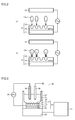
- Fig. 3 is a diagram showing the schematic configuration of a QCM sensor.
- a QCM sensor 33 includes a cell 27 storing a solution, a crystal oscillator 32 disposed at the bottom of cell 27, an oscillation circuit 22, and a controller 21 having a frequency counter.
- Crystal oscillator 32 is formed by stacking detection unit 17 produced by the steps shown in Fig. 1 , a crystal piece 24, and a counter electrode (second counter electrode) 23 in this order.
- QCM sensor 33 further includes a counter electrode (first counter electrode) 16 and a reference electrode 30 immersed in a sample solution 31, and also includes an AC power supply 29 connected to detection electrode 11 of detection unit 17 and counter electrode 16.
- sample solution 31 is added to cell 27.
- AC power supply 29 applies an AC voltage between detection electrode 11 and counter electrode 16, thereby causing microorganisms contained in sample solution 31 to be moved toward detection unit 17 by dielectrophoresis.
- oscillation circuit 22 applies an AC voltage between detection electrode 11 and counter electrode 23 to cause crystal piece 24 to oscillate.
- the frequency counter within controller 21 receives a signal from oscillation circuit 22 and measures a resonance frequency value. The state of capturing microorganisms is detected based on the change in the resonance frequency value.
- a polymer layer can be formed on detection electrode 11 in accordance with the step of roughening the surface of detection electrode 11 and the steps shown in Fig. 1 .
- the crystal oscillator formed by stacking detection electrode 11, crystal piece 24 and counter electrode 23 in this order is disposed at the bottom of cell 27, and a direct-current (DC) power supply is connected in place of AC power supply 29.
- DC direct-current
- bacteria can also be detected in a few minutes to several dozen minutes, in which case bacteria can be detected much more quickly than in the case of the cultural method. Furthermore, since bacteria can be detected without using for example a staining reagent required for fluorescent staining and an ATP extracting reagent required for measuring the number of bacteria by the ATP, the sensor of the present invention can be readily automated or installed in devices such as a water filter, a water server or an automatic ice maker. Furthermore, the sensor of the present invention can also be used in a water purification plant and a beverage/food factory as a tool for a bacteria test in the water quality inspection and the food inspection.
- bacteria within equipment such as a water storage tank and a piping channel can be automatically detected, the detection result can be informed to the user, and measures such as sterilization, cleaning and the like can be automatically taken.
- the sensor of the present invention can also be installed as a device in the piping line of clean water in a water purification plant to detect bacteria in the water to be supplied.
- the polymer layer in the above-described sensor can be used not only for a component of the sensor but also for a microorganism capturing device, a microorganism shape-recognizing device and a microorganism tracking device each utilizing a feature of a mold having a three-dimensional structure complementary to the steric structure of a microorganism, and also for a catalyst carrier utilizing a feature of a porous body, and the like.
- a polymer layer was produced using an electrochemistry measurement system (Model842B manufactured by ALS).
- a gold electrode (corresponding to electrode 11 that is one of electrodes in a crystal oscillator) was used for a detection electrode; Ag/AgCl (saturation KCl) was used for a reference electrode; and a Pt rod (having a diameter of 1 mm, a length of 4 cm and manufactured by Nilaco corporation) was used for a counter electrode (first counter electrode).
- the electric potential is indicated as a value with respect to the electric potential of this reference electrode.
- a crystal oscillator having both surfaces each provided with a gold electrode an electrode area of 0.196 cm 2 , a fundamental oscillation frequency of 9 MHz, AT cut, a square shape, and manufactured by SEIKO EG & G CO., LTD. was used.
- Example 1 Pseudomonas aeruginosa (zeta potential: -33.87 mV) was used as a microorganism to be detected.
- Example 2 Acinetobacter calcoaceticus (zeta potential: -28.14 mV) was used.
- Example 3 Escherichia coli were used.
- Example 5 Pseudomonas aeruginosa, Escherichia coli, Acinetobacter calcoaceticus, and Serratia marcescens were used.
- Figs. 4 and 5 show electron microscope photographs of Pseudomonas aeruginosa and Acinetobacter calcoaceticus, respectively.
- a peroxidized polypyrrole layer was produced on the gold electrode in accordance with the following procedure.
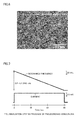
- Fig. 6 shows an electron microscope photograph of the surface of the polypyrrole layer after the polymerization step. It was observed how Pseudomonas aeruginosa were captured in the surface of the polypyrrole layer.
- Fig. 7 is a graph showing the relation between the time and the current, and the relation between the time and the resonance frequency of the crystal oscillator in the polymerization step. The point of time at which the controlled potential electrolysis is started is set at 0 second.
- Fig. 8 is a graph showing the relation between the time and the mass change obtained by calculating the amount of mass change of the crystal oscillator based on the amount of change in the resonance frequency shown in Fig. 7 . These graphs show that the mass of the surface of the crystal oscillator increased in proportion to the electrolysis time, and a sufficient mass change, that is, sufficient polymerization of the polypyrrole layer, was achieved in 90 seconds.
- Fig. 9 shows an electron microscope photograph of the surface of the peroxidized polypyrrole layer after the bacteriolysis step and the peroxidation step. Pseudomonas aeruginosa were not observed on the surface of the peroxidized polypyrrole layer. Accordingly, it is found that Pseudomonas aeruginosa were released from the surface of the peroxidized polypyrrole layer.
- Fig. 10 shows an electron microscope photograph of the surface of the peroxidized polypyrrole layer produced on the conditions different from those of the above-described Example 1 in the shaking time period after dripping lysozyme and the shaking time period after adding a nonionic surface-active agent in the bacteriolysis step. Fig.
- FIG. 10(a) shows an electron microscope photograph in the case where the shaking time period after dripping lysozyme was set at 30 minutes and the shaking time period after adding a nonionic surface-active agent was set at 20 minutes.
- Fig. 10(b) shows an electron microscope photograph in the case where the shaking time period after dripping lysozyme was set at 60 minutes and the shaking time period after adding a nonionic surface-active agent was set at 40 minutes.
- Fig. 10(c) shows an electron microscope photograph in the case where the shaking time period after dripping lysozyme was set at 90 minutes and the shaking time period after adding a nonionic surface-active agent was set at 60 minutes. It can be seen from Figs. 10(a) to 10(c) that Pseudomonas aeruginosa are not sufficiently released under the above-described conditions, and therefore, it is suitable to employ the condition for the bacteriolysis step in Example 1.
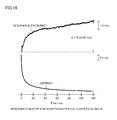
- Fig. 11 is a graph showing the relation between the time and the current, and the relation between the time and the resonance frequency of the crystal oscillator in the peroxidation step.
- the time at which a constant electrical potential is applied in the peroxidation step is set at 0 second. It is found that the current value decreases with time, and the peroxidation process progresses. It is also found that the resonance frequency increases and the mass of the electrode surface decreases. It is understood that this is caused by releasing Pseudomonas aeruginosa.
- Microorganisms were detected using a QCM sensor having a crystal oscillator provided at the bottom of a cell.
- This crystal oscillator had a surface on which a peroxidized polypyrrole layer produced as described above and having a Pseudomonas aeruginosa mold was formed.
- a sample solution containing microorganisms was added into the cell. Then, an AC voltage was applied between a gold electrode and the first counter electrode, to cause the microorganisms to be concentrated on the surface of the peroxidized polypyrrole layer by dielectrophoresis.
- a waveform generator 7075; manufactured by HIOKI E.E.
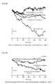
- Fig. 12 is a graph showing the relation between the time of applying an AC voltage and the resonance frequency of the crystal oscillator. It has been found from the results shown in Fig. 12 that the resonance frequency greatly decreased in the detection experiment in which a sample solution containing Pseudomonas aeruginosa was added. The decrease in resonance frequency means that the mass of the surface of the crystal oscillator has increased. It is considered that dielectrophoretic force acted on Pseudomonas aeruginosa, which was then captured in the mold of the peroxidized polypyrrole layer, with the result that the mass of the surface of the crystal oscillator has increased.
- Acinetobacter calcoaceticus having a shape different from the mold there has been almost no change in the mass as in the case of a blank. Therefore, it is considered that Acinetobacter calcoaceticus having a shape different from the mold is not so readily captured in the peroxidized polypyrrole layer as compared with Pseudomonas aeruginosa. Thus, it can be determined that the sensor recognizes the type of bacteria with high accuracy.
- the step of roughening the surface of the gold electrode, the polymerization step, the bacteriolysis step and the peroxidation step were performed as in Example 1 except that Acinetobacter calcoaceticus was used in place of Pseudomonas aeruginosa in Example 1.
- Fig. 13 shows an electron microscope photograph of the surface of the polypyrrole layer after the polymerization step. It was observed how Acinetobacter calcoaceticus was captured in the surface of the polypyrrole layer.
- Fig. 14 is a graph showing the relation between the time and the current, and the relation between the time and the resonance frequency of the crystal oscillator in the polymerization step. The time at which the controlled potential electrolysis is started is set at 0 second. This graph shows that the mass of the surface of the crystal oscillator increased in proportion to the electrolysis time.
- Fig. 15 is an electron microscope photograph of the surface of the peroxidized polypyrrole layer after the bacteriolysis step and the peroxidation step. No Acinetobacter calcoaceticus was observed on the surface of the peroxidized polypyrrole layer. Accordingly, it is found that Acinetobacter calcoaceticus was released from the surface of the peroxidized polypyrrole layer.
- Fig. 16 is a graph showing the relation between the time and the current, and the relation between the time and the resonance frequency of the crystal oscillator in the peroxidation step.
- the time at which a constant electrical potential is applied in the peroxidation step is set at 0 second. It is found that the current value decreases with time, and the peroxidation step progresses. It is also found that the resonance frequency increases and the mass of the electrode surface decreases. It is understood that this is caused by releasing Acinetobacter calcoaceticus.
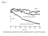
- Microorganisms were detected using a QCM sensor having a crystal oscillator provided at the bottom of a cell.
- This crystal oscillator had a surface on which a peroxidized polypyrrole layer produced as described above and having an Acinetobacter calcoaceticus mold was formed.
- the same experimental conditions as those in Example 1 were used.
- Fig. 17 is a graph showing the relation between the time of applying an AC voltage and the resonance frequency of the crystal oscillator. It has been found from the results shown in Fig. 17 that the resonance frequency greatly decreased in the detection experiment in which the sample solution containing Acinetobacter calcoaceticus was added. The decrease in resonance frequency means that the mass of the surface of the crystal oscillator has increased. Thus, it is considered that dielectrophoretic force acted on Acinetobacter calcoaceticus, which was then captured in the mold of the peroxidized polypyrrole layer, with the result that the mass of the surface of the crystal oscillator has increased.
- the step of roughening the surface of the gold electrode, the polymerization step, the bacteriolysis step and the peroxidation step were performed as in Example 1 except that Escherichia coli were used in place of Pseudomonas aeruginosa in Example 1.
- Microorganisms were detected using a QCM sensor having a crystal oscillator provided at the bottom of a cell.
- This crystal oscillator had a surface on which a peroxidized polypyrrole layer produced as described above and having an Escherichia coli mold was formed.
- solutions of Pseudomonas aeruginosa, Escherichia coli and Acinetobacter calcoaceticus, respectively, were used.
- Fig. 18 is a graph showing the relation between the time of applying an AC voltage and the resonance frequency of the crystal oscillator. It has been found from the results shown in Fig. 18 that the resonance frequency greatly decreased in the detection experiment in which the sample solution containing Escherichia coli was added. The decrease in resonance frequency means that the mass of the surface of the crystal oscillator has increased. Thus, it is considered that dielectrophoretic force acted on Escherichia coli, which was then captured in the mold of the peroxidized polypyrrole layer, with the result that the mass of the surface of the crystal oscillator has increased.
- Example 1 Using Pseudomonas aeruginosa, the step of roughening the surface of the gold electrode, the polymerization step, the bacteriolysis step and the peroxidation step were performed as in Example 1.
- Microorganisms were detected using a QCM sensor having a crystal oscillator provided at the bottom of a cell.
- This crystal oscillator had a surface on which a peroxidized polypyrrole layer produced as described above and having a Pseudomonas aeruginosa mold was formed.
- As measurement samples two types of solutions were used, including a solution (a) obtained by mixing solutions of Pseudomonas aeruginosa, Escherichia coli, Acinetobacter calcoaceticus, and serratia bacteria; and a solution (b) obtained by mixing solutions of Escherichia coli, Acinetobacter calcoaceticus and serratia bacteria.
- Fig. 19 is a graph showing the relation between the time of applying an AC voltage and the resonance frequency of the crystal oscillator. It has been found from the results shown in Fig. 19 that the resonance frequency greatly decreased in the detection experiment in which the sample solution containing Pseudomonas aeruginosa was added. The decrease in resonance frequency means that the mass of the surface of the crystal oscillator has increased. Thus, it is considered that dielectrophoretic force acted on Pseudomonas aeruginosa, which was then captured in the mold of the peroxidized polypyrrole layer, with the result that the mass of the surface of the crystal oscillator has increased.
- Escherichia coli, Acinetobacter calcoaceticus and Serratia bacteria each having a shape different from the mold there has been almost no change in the mass as in the case of a blank (c). Therefore, it is considered that Escherichia coli, Acinetobacter calcoaceticus and Serratia bacteria each having a shape different from the mold is not so readily captured in the peroxidized polypyrrole layer as compared with Pseudomonas aeruginosa. Thus, it can be determined that the sensor recognizes the type of bacteria with high accuracy.
- Example 1 Using a modified solution containing all of Pseudomonas aeruginosa, Escherichia coli, Acinetobacter calcoaceticus, and serratia bacteria, the step of roughening the surface of the gold electrode, the polymerization step, the bacteriolysis step and the peroxidation step were performed as in Example 1.
- Microorganisms were detected using a QCM sensor having a crystal oscillator provided at the bottom of a cell.
- This crystal oscillator had a surface on which a peroxidized polypyrrole layer produced as described above and having molds including four types of microorganisms was formed.
- As measurement samples four types of solutions containing Pseudomonas aeruginosa, Escherichia coli, Acinetobacter calcoaceticus, and serratia bacteria, respectively, were used.
- Figs. 20 to 23 each are a graph showing the relation between the time of applying an AC voltage and the resonance frequency of the crystal oscillator.
- Figs. 20 to 23 show the results in the detection experiments in which sample solutions containing Pseudomonas aeruginosa, Escherichia coli, Acinetobacter calcoaceticus, and serratia bacteria, respectively, were added. It has been found that the resonance frequency greatly decreased when any of the sample solutions was added. Accordingly, it can be determined that a plurality of types of microorganisms are detected by the sensor having molds of a plurality of types of microorganisms.
Landscapes
- Health & Medical Sciences (AREA)
- Life Sciences & Earth Sciences (AREA)
- Chemical & Material Sciences (AREA)
- Engineering & Computer Science (AREA)
- Immunology (AREA)
- Molecular Biology (AREA)
- Organic Chemistry (AREA)
- Biomedical Technology (AREA)
- Urology & Nephrology (AREA)
- Hematology (AREA)
- Biochemistry (AREA)
- Physics & Mathematics (AREA)
- Microbiology (AREA)
- Biotechnology (AREA)
- General Health & Medical Sciences (AREA)
- Analytical Chemistry (AREA)
- Proteomics, Peptides & Aminoacids (AREA)
- Zoology (AREA)
- Wood Science & Technology (AREA)
- Medicinal Chemistry (AREA)
- Food Science & Technology (AREA)
- General Physics & Mathematics (AREA)
- Pathology (AREA)
- Cell Biology (AREA)
- Toxicology (AREA)
- Metallurgy (AREA)
- Materials Engineering (AREA)
- Biophysics (AREA)
- Electrochemistry (AREA)
- Chemical Kinetics & Catalysis (AREA)
- Bioinformatics & Cheminformatics (AREA)
- General Engineering & Computer Science (AREA)
- Genetics & Genomics (AREA)
- Tropical Medicine & Parasitology (AREA)
- Virology (AREA)
- Apparatus Associated With Microorganisms And Enzymes (AREA)
- Measuring Or Testing Involving Enzymes Or Micro-Organisms (AREA)
Applications Claiming Priority (2)
| Application Number | Priority Date | Filing Date | Title |
|---|---|---|---|
| JP2011050416 | 2011-03-08 | ||
| PCT/JP2012/055611 WO2012121229A1 (fr) | 2011-03-08 | 2012-03-06 | Capteur pour détecter les micro-organismes et son procédé de fabrication |
Publications (3)
| Publication Number | Publication Date |
|---|---|
| EP2684946A1 true EP2684946A1 (fr) | 2014-01-15 |
| EP2684946A4 EP2684946A4 (fr) | 2015-01-07 |
| EP2684946B1 EP2684946B1 (fr) | 2018-11-21 |
Family
ID=46798187
Family Applications (1)
| Application Number | Title | Priority Date | Filing Date |
|---|---|---|---|
| EP12754214.0A Active EP2684946B1 (fr) | 2011-03-08 | 2012-03-06 | Capteur pour détecter les micro-organismes et son procédé de fabrication |
Country Status (5)
| Country | Link |
|---|---|
| US (1) | US9206461B2 (fr) |
| EP (1) | EP2684946B1 (fr) |
| JP (1) | JP6014582B2 (fr) |
| CN (1) | CN103459583B (fr) |
| WO (1) | WO2012121229A1 (fr) |
Cited By (1)
| Publication number | Priority date | Publication date | Assignee | Title |
|---|---|---|---|---|
| EP3139166A4 (fr) * | 2014-05-02 | 2017-04-19 | Osaka Prefecture University Public Corporation | Film de polymère pour détection de cellules cancéreuses et son procédé de fabrication, et dispositif de détection de cellules cancéreuses utilisant un tel film de polymère |
Families Citing this family (15)
| Publication number | Priority date | Publication date | Assignee | Title |
|---|---|---|---|---|
| US9890991B2 (en) | 2013-03-14 | 2018-02-13 | Whirlpool Corporation | Domestic appliance including piezoelectric components |
| EP2980204A4 (fr) * | 2013-03-28 | 2016-10-19 | Sharp Kk | Capteur de détection de micro-organisme, son procédé de fabrication, et couche polymère |
| JP6358610B2 (ja) * | 2013-08-26 | 2018-07-18 | 公立大学法人大阪府立大学 | 被検出微生物を検出する検出方法 |
| CN103454331B (zh) * | 2013-09-06 | 2015-09-30 | 南京理工大学 | 过氧化pedot/go修饰电极及其对农药吡虫啉的电化学检测方法 |
| CN114089597B (zh) | 2013-12-19 | 2025-03-14 | Illumina公司 | 包括纳米图案化表面的基底及其制备方法 |
| CN104928348A (zh) * | 2015-06-29 | 2015-09-23 | 苏州东辰林达检测技术有限公司 | 肉制品中沙门氏菌的检测方法 |
| JP6171124B2 (ja) * | 2015-10-07 | 2017-08-02 | 株式会社Afiテクノロジー | 検査装置、検査システム、及び検査方法 |
| JP6676486B2 (ja) * | 2016-04-05 | 2020-04-08 | シャープ株式会社 | 検出方法 |
| WO2017175879A1 (fr) * | 2016-04-05 | 2017-10-12 | シャープ株式会社 | Dispositif de capteur, procédé de détection et unité de capteur |
| CN106645348B (zh) * | 2016-12-23 | 2019-03-05 | 南开大学 | 一种高稳定微生物电化学传感器的制备方法 |
| CN108241056A (zh) * | 2016-12-23 | 2018-07-03 | 财团法人金属工业研究发展中心 | 生物检测装置 |
| JP2020091218A (ja) * | 2018-12-06 | 2020-06-11 | 東ソー株式会社 | 機能性物質固定化粒子の保持方法 |
| KR102134394B1 (ko) * | 2018-12-17 | 2020-07-16 | 한국과학기술연구원 | 수직 나노갭 전극을 이용한 유전영동 방법에 의한 고효율 바이오연료 생산 균주의 선별방법 |
| KR20240112250A (ko) * | 2021-07-19 | 2024-07-18 | 인피콘, 인크. | 신속한 등록 응답을 갖는 수정 결정 미소저울 (qcm) 센서 |
| CN118655199B (zh) * | 2024-08-19 | 2024-12-24 | 四川菊乐食品股份有限公司 | 一种细胞印迹电化学传感器的制备方法及利用其快速定量检测乳制品中乳酸菌的方法 |
Family Cites Families (7)
| Publication number | Priority date | Publication date | Assignee | Title |
|---|---|---|---|---|
| US6596532B1 (en) * | 1997-12-12 | 2003-07-22 | BIOMéRIEUX, INC. | Device for isolation and surface culture of microorganisms from bulk fluids |
| RU2161653C2 (ru) * | 1998-08-24 | 2001-01-10 | ФАРМАКОВСКИЙ Дмитрий Александрович | Способ количественного электрохимического анализа биомолекул |
| US6582971B1 (en) * | 2000-08-21 | 2003-06-24 | Lynntech, Inc. | Imprinting large molecular weight compounds in polymer composites |
| US20040126814A1 (en) * | 2000-08-21 | 2004-07-01 | Singh Waheguru Pal | Sensor having molecularly imprinted polymers |
| US20090012446A1 (en) * | 2007-07-03 | 2009-01-08 | Xinyan Cui | Devices, systems and methods for release of chemical agents |
| JP5007905B2 (ja) * | 2007-08-29 | 2012-08-22 | 公立大学法人大阪府立大学 | 分子鋳型を有するポリマーを備えたセンサー |
| US20120258444A1 (en) * | 2010-11-18 | 2012-10-11 | Therrien Joel M | Acoustic wave (aw) sensing devices using live cells |
-
2012
- 2012-03-06 EP EP12754214.0A patent/EP2684946B1/fr active Active
- 2012-03-06 JP JP2013503547A patent/JP6014582B2/ja active Active
- 2012-03-06 US US14/003,613 patent/US9206461B2/en active Active
- 2012-03-06 CN CN201280011897.7A patent/CN103459583B/zh not_active Expired - Fee Related
- 2012-03-06 WO PCT/JP2012/055611 patent/WO2012121229A1/fr not_active Ceased
Cited By (1)
| Publication number | Priority date | Publication date | Assignee | Title |
|---|---|---|---|---|
| EP3139166A4 (fr) * | 2014-05-02 | 2017-04-19 | Osaka Prefecture University Public Corporation | Film de polymère pour détection de cellules cancéreuses et son procédé de fabrication, et dispositif de détection de cellules cancéreuses utilisant un tel film de polymère |
Also Published As
| Publication number | Publication date |
|---|---|
| EP2684946B1 (fr) | 2018-11-21 |
| US9206461B2 (en) | 2015-12-08 |
| CN103459583B (zh) | 2015-11-25 |
| US20130337498A1 (en) | 2013-12-19 |
| EP2684946A4 (fr) | 2015-01-07 |
| WO2012121229A1 (fr) | 2012-09-13 |
| JPWO2012121229A1 (ja) | 2014-07-17 |
| JP6014582B2 (ja) | 2016-10-25 |
| CN103459583A (zh) | 2013-12-18 |
Similar Documents
| Publication | Publication Date | Title |
|---|---|---|
| EP2684946B1 (fr) | Capteur pour détecter les micro-organismes et son procédé de fabrication | |
| Wu et al. | Efficient capture, rapid killing and ultrasensitive detection of bacteria by a nano-decorated multi-functional electrode sensor | |
| Devi et al. | Construction and application of an amperometric xanthine biosensor based on zinc oxide nanoparticles–polypyrrole composite film | |
| Gall et al. | The effect of electric fields on bacterial attachment to conductive surfaces | |
| Muñoz-Berbel et al. | On-chip impedance measurements to monitor biofilm formation in the drinking water distribution network | |
| Ge et al. | Target-induced aptamer displacement on gold nanoparticles and rolling circle amplification for ultrasensitive live Salmonella typhimurium electrochemical biosensing | |
| Kahraman et al. | On sample preparation for surface-enhanced Raman scattering (SERS) of bacteria and the source of spectral features of the spectra | |
| Guterman et al. | Electrical conductivity, selective adhesion, and biocompatibility in bacteria‐inspired peptide–metal self‐supporting nanocomposites | |
| JP6077106B2 (ja) | 微生物検出用センサー、その製造方法、およびポリマー層 | |
| CN106770563A (zh) | 一种检测水体急性生物毒性的双电子介体电化学生物传感器及其应用 | |
| Pandey et al. | Cationic poly (lactic-co-glycolic acid) iron oxide microspheres for nucleic acid detection | |
| Kinoshita et al. | Real-time evaluation of bacterial viability using gold nanoparticles | |
| EP3918306A1 (fr) | Procédé de détection et de quantification de particules de plastique nanométriques ou micrométriques | |
| JP2003000224A (ja) | 微生物活性測定装置及び微生物活性の測定方法 | |
| WO2012167218A2 (fr) | Dispositif et procédé d'identification de microbes et de comptage de microbes et de détermination de la sensibilité antimicrobienne | |
| Patel et al. | Impedance based biosensor for agricultural pathogen detection | |
| Cotta et al. | A 3D porous electrode for real-time monitoring of microalgal growth and exopolysaccharides yields using Electrochemical Impedance Spectroscopy | |
| Burç et al. | High-sensitivity electrochemical sensor using no nanomaterials for the detection of ciprofloxacin with poly 2-(hydroxymethyl) thiophene-modified glassy carbon electrode | |
| EP4028539B1 (fr) | Mesurer la sensibilité antimicrobienne des microbes | |
| Verma et al. | ZnO/MWCNTs/Au Based Nano Biosensor for Detection of Lactate in Food Samples | |
| WO2015044191A1 (fr) | Procédé pour isoler des agents pathogènes | |
| Baecker et al. | Sensor system for the monitoring of degradation processes of biodegradable biopolymers | |
| JP4536264B2 (ja) | 微生物の生物学的活性の有無を決定する方法 | |
| WO2019168837A1 (fr) | Détection de cellules vivantes | |
| CN101646401B (zh) | 用于自动检测蛋白质的生物兼容支架材料 |
Legal Events
| Date | Code | Title | Description |
|---|---|---|---|
| PUAI | Public reference made under article 153(3) epc to a published international application that has entered the european phase |
Free format text: ORIGINAL CODE: 0009012 |
|
| 17P | Request for examination filed |
Effective date: 20131001 |
|
| AK | Designated contracting states |
Kind code of ref document: A1 Designated state(s): AL AT BE BG CH CY CZ DE DK EE ES FI FR GB GR HR HU IE IS IT LI LT LU LV MC MK MT NL NO PL PT RO RS SE SI SK SM TR |
|
| DAX | Request for extension of the european patent (deleted) | ||
| A4 | Supplementary search report drawn up and despatched |
Effective date: 20141210 |
|
| RIC1 | Information provided on ipc code assigned before grant |
Ipc: C12Q 1/04 20060101ALN20141204BHEP Ipc: C12M 1/34 20060101AFI20141204BHEP Ipc: G01N 33/543 20060101ALI20141204BHEP Ipc: C25D 5/00 20060101ALN20141204BHEP Ipc: G01N 33/569 20060101ALI20141204BHEP |
|
| STAA | Information on the status of an ep patent application or granted ep patent |
Free format text: STATUS: EXAMINATION IS IN PROGRESS |
|
| 17Q | First examination report despatched |
Effective date: 20161219 |
|
| RAP1 | Party data changed (applicant data changed or rights of an application transferred) |
Owner name: OSAKA PREFECTURE UNIVERSITY PUBLIC CORPORATION Owner name: SHARP LIFE SCIENCE CORPORATION |
|
| RIC1 | Information provided on ipc code assigned before grant |
Ipc: G01N 33/543 20060101ALI20180516BHEP Ipc: C25D 5/00 20060101ALN20180516BHEP Ipc: C12M 1/34 20060101AFI20180516BHEP Ipc: G01N 33/569 20060101ALI20180516BHEP Ipc: C12Q 1/04 20060101ALN20180516BHEP |
|
| GRAP | Despatch of communication of intention to grant a patent |
Free format text: ORIGINAL CODE: EPIDOSNIGR1 |
|
| STAA | Information on the status of an ep patent application or granted ep patent |
Free format text: STATUS: GRANT OF PATENT IS INTENDED |
|
| INTG | Intention to grant announced |
Effective date: 20180712 |
|
| RAP1 | Party data changed (applicant data changed or rights of an application transferred) |
Owner name: OSAKA PREFECTURE UNIVERSITY PUBLIC CORPORATION |
|
| GRAS | Grant fee paid |
Free format text: ORIGINAL CODE: EPIDOSNIGR3 |
|
| GRAA | (expected) grant |
Free format text: ORIGINAL CODE: 0009210 |
|
| STAA | Information on the status of an ep patent application or granted ep patent |
Free format text: STATUS: THE PATENT HAS BEEN GRANTED |
|
| AK | Designated contracting states |
Kind code of ref document: B1 Designated state(s): AL AT BE BG CH CY CZ DE DK EE ES FI FR GB GR HR HU IE IS IT LI LT LU LV MC MK MT NL NO PL PT RO RS SE SI SK SM TR |
|
| REG | Reference to a national code |
Ref country code: CH Ref legal event code: EP |
|
| REG | Reference to a national code |
Ref country code: IE Ref legal event code: FG4D |
|
| REG | Reference to a national code |
Ref country code: DE Ref legal event code: R096 Ref document number: 602012053809 Country of ref document: DE |
|
| REG | Reference to a national code |
Ref country code: AT Ref legal event code: REF Ref document number: 1067538 Country of ref document: AT Kind code of ref document: T Effective date: 20181215 |
|
| REG | Reference to a national code |
Ref country code: NL Ref legal event code: MP Effective date: 20181121 |
|
| REG | Reference to a national code |
Ref country code: AT Ref legal event code: MK05 Ref document number: 1067538 Country of ref document: AT Kind code of ref document: T Effective date: 20181121 |
|
| PG25 | Lapsed in a contracting state [announced via postgrant information from national office to epo] |
Ref country code: ES Free format text: LAPSE BECAUSE OF FAILURE TO SUBMIT A TRANSLATION OF THE DESCRIPTION OR TO PAY THE FEE WITHIN THE PRESCRIBED TIME-LIMIT Effective date: 20181121 Ref country code: AT Free format text: LAPSE BECAUSE OF FAILURE TO SUBMIT A TRANSLATION OF THE DESCRIPTION OR TO PAY THE FEE WITHIN THE PRESCRIBED TIME-LIMIT Effective date: 20181121 Ref country code: NO Free format text: LAPSE BECAUSE OF FAILURE TO SUBMIT A TRANSLATION OF THE DESCRIPTION OR TO PAY THE FEE WITHIN THE PRESCRIBED TIME-LIMIT Effective date: 20190221 Ref country code: IS Free format text: LAPSE BECAUSE OF FAILURE TO SUBMIT A TRANSLATION OF THE DESCRIPTION OR TO PAY THE FEE WITHIN THE PRESCRIBED TIME-LIMIT Effective date: 20190321 Ref country code: BG Free format text: LAPSE BECAUSE OF FAILURE TO SUBMIT A TRANSLATION OF THE DESCRIPTION OR TO PAY THE FEE WITHIN THE PRESCRIBED TIME-LIMIT Effective date: 20190221 Ref country code: LT Free format text: LAPSE BECAUSE OF FAILURE TO SUBMIT A TRANSLATION OF THE DESCRIPTION OR TO PAY THE FEE WITHIN THE PRESCRIBED TIME-LIMIT Effective date: 20181121 Ref country code: FI Free format text: LAPSE BECAUSE OF FAILURE TO SUBMIT A TRANSLATION OF THE DESCRIPTION OR TO PAY THE FEE WITHIN THE PRESCRIBED TIME-LIMIT Effective date: 20181121 Ref country code: LV Free format text: LAPSE BECAUSE OF FAILURE TO SUBMIT A TRANSLATION OF THE DESCRIPTION OR TO PAY THE FEE WITHIN THE PRESCRIBED TIME-LIMIT Effective date: 20181121 Ref country code: HR Free format text: LAPSE BECAUSE OF FAILURE TO SUBMIT A TRANSLATION OF THE DESCRIPTION OR TO PAY THE FEE WITHIN THE PRESCRIBED TIME-LIMIT Effective date: 20181121 |
|
| PG25 | Lapsed in a contracting state [announced via postgrant information from national office to epo] |
Ref country code: NL Free format text: LAPSE BECAUSE OF FAILURE TO SUBMIT A TRANSLATION OF THE DESCRIPTION OR TO PAY THE FEE WITHIN THE PRESCRIBED TIME-LIMIT Effective date: 20181121 Ref country code: RS Free format text: LAPSE BECAUSE OF FAILURE TO SUBMIT A TRANSLATION OF THE DESCRIPTION OR TO PAY THE FEE WITHIN THE PRESCRIBED TIME-LIMIT Effective date: 20181121 Ref country code: SE Free format text: LAPSE BECAUSE OF FAILURE TO SUBMIT A TRANSLATION OF THE DESCRIPTION OR TO PAY THE FEE WITHIN THE PRESCRIBED TIME-LIMIT Effective date: 20181121 Ref country code: AL Free format text: LAPSE BECAUSE OF FAILURE TO SUBMIT A TRANSLATION OF THE DESCRIPTION OR TO PAY THE FEE WITHIN THE PRESCRIBED TIME-LIMIT Effective date: 20181121 Ref country code: PT Free format text: LAPSE BECAUSE OF FAILURE TO SUBMIT A TRANSLATION OF THE DESCRIPTION OR TO PAY THE FEE WITHIN THE PRESCRIBED TIME-LIMIT Effective date: 20190321 Ref country code: GR Free format text: LAPSE BECAUSE OF FAILURE TO SUBMIT A TRANSLATION OF THE DESCRIPTION OR TO PAY THE FEE WITHIN THE PRESCRIBED TIME-LIMIT Effective date: 20190222 |
|
| PG25 | Lapsed in a contracting state [announced via postgrant information from national office to epo] |
Ref country code: PL Free format text: LAPSE BECAUSE OF FAILURE TO SUBMIT A TRANSLATION OF THE DESCRIPTION OR TO PAY THE FEE WITHIN THE PRESCRIBED TIME-LIMIT Effective date: 20181121 Ref country code: DK Free format text: LAPSE BECAUSE OF FAILURE TO SUBMIT A TRANSLATION OF THE DESCRIPTION OR TO PAY THE FEE WITHIN THE PRESCRIBED TIME-LIMIT Effective date: 20181121 Ref country code: CZ Free format text: LAPSE BECAUSE OF FAILURE TO SUBMIT A TRANSLATION OF THE DESCRIPTION OR TO PAY THE FEE WITHIN THE PRESCRIBED TIME-LIMIT Effective date: 20181121 Ref country code: IT Free format text: LAPSE BECAUSE OF FAILURE TO SUBMIT A TRANSLATION OF THE DESCRIPTION OR TO PAY THE FEE WITHIN THE PRESCRIBED TIME-LIMIT Effective date: 20181121 |
|
| REG | Reference to a national code |
Ref country code: DE Ref legal event code: R097 Ref document number: 602012053809 Country of ref document: DE |
|
| PG25 | Lapsed in a contracting state [announced via postgrant information from national office to epo] |
Ref country code: SK Free format text: LAPSE BECAUSE OF FAILURE TO SUBMIT A TRANSLATION OF THE DESCRIPTION OR TO PAY THE FEE WITHIN THE PRESCRIBED TIME-LIMIT Effective date: 20181121 Ref country code: RO Free format text: LAPSE BECAUSE OF FAILURE TO SUBMIT A TRANSLATION OF THE DESCRIPTION OR TO PAY THE FEE WITHIN THE PRESCRIBED TIME-LIMIT Effective date: 20181121 Ref country code: EE Free format text: LAPSE BECAUSE OF FAILURE TO SUBMIT A TRANSLATION OF THE DESCRIPTION OR TO PAY THE FEE WITHIN THE PRESCRIBED TIME-LIMIT Effective date: 20181121 Ref country code: SM Free format text: LAPSE BECAUSE OF FAILURE TO SUBMIT A TRANSLATION OF THE DESCRIPTION OR TO PAY THE FEE WITHIN THE PRESCRIBED TIME-LIMIT Effective date: 20181121 |
|
| PLBE | No opposition filed within time limit |
Free format text: ORIGINAL CODE: 0009261 |
|
| STAA | Information on the status of an ep patent application or granted ep patent |
Free format text: STATUS: NO OPPOSITION FILED WITHIN TIME LIMIT |
|
| 26N | No opposition filed |
Effective date: 20190822 |
|
| PG25 | Lapsed in a contracting state [announced via postgrant information from national office to epo] |
Ref country code: MC Free format text: LAPSE BECAUSE OF FAILURE TO SUBMIT A TRANSLATION OF THE DESCRIPTION OR TO PAY THE FEE WITHIN THE PRESCRIBED TIME-LIMIT Effective date: 20181121 Ref country code: SI Free format text: LAPSE BECAUSE OF FAILURE TO SUBMIT A TRANSLATION OF THE DESCRIPTION OR TO PAY THE FEE WITHIN THE PRESCRIBED TIME-LIMIT Effective date: 20181121 |
|
| REG | Reference to a national code |
Ref country code: CH Ref legal event code: PL |
|
| PG25 | Lapsed in a contracting state [announced via postgrant information from national office to epo] |
Ref country code: LU Free format text: LAPSE BECAUSE OF NON-PAYMENT OF DUE FEES Effective date: 20190306 |
|
| REG | Reference to a national code |
Ref country code: BE Ref legal event code: MM Effective date: 20190331 |
|
| PG25 | Lapsed in a contracting state [announced via postgrant information from national office to epo] |
Ref country code: LI Free format text: LAPSE BECAUSE OF NON-PAYMENT OF DUE FEES Effective date: 20190331 Ref country code: CH Free format text: LAPSE BECAUSE OF NON-PAYMENT OF DUE FEES Effective date: 20190331 Ref country code: IE Free format text: LAPSE BECAUSE OF NON-PAYMENT OF DUE FEES Effective date: 20190306 |
|
| PG25 | Lapsed in a contracting state [announced via postgrant information from national office to epo] |
Ref country code: BE Free format text: LAPSE BECAUSE OF NON-PAYMENT OF DUE FEES Effective date: 20190331 |
|
| PG25 | Lapsed in a contracting state [announced via postgrant information from national office to epo] |
Ref country code: TR Free format text: LAPSE BECAUSE OF FAILURE TO SUBMIT A TRANSLATION OF THE DESCRIPTION OR TO PAY THE FEE WITHIN THE PRESCRIBED TIME-LIMIT Effective date: 20181121 |
|
| PG25 | Lapsed in a contracting state [announced via postgrant information from national office to epo] |
Ref country code: MT Free format text: LAPSE BECAUSE OF NON-PAYMENT OF DUE FEES Effective date: 20190306 |
|
| PG25 | Lapsed in a contracting state [announced via postgrant information from national office to epo] |
Ref country code: CY Free format text: LAPSE BECAUSE OF FAILURE TO SUBMIT A TRANSLATION OF THE DESCRIPTION OR TO PAY THE FEE WITHIN THE PRESCRIBED TIME-LIMIT Effective date: 20181121 |
|
| PG25 | Lapsed in a contracting state [announced via postgrant information from national office to epo] |
Ref country code: HU Free format text: LAPSE BECAUSE OF FAILURE TO SUBMIT A TRANSLATION OF THE DESCRIPTION OR TO PAY THE FEE WITHIN THE PRESCRIBED TIME-LIMIT; INVALID AB INITIO Effective date: 20120306 |
|
| PG25 | Lapsed in a contracting state [announced via postgrant information from national office to epo] |
Ref country code: MK Free format text: LAPSE BECAUSE OF FAILURE TO SUBMIT A TRANSLATION OF THE DESCRIPTION OR TO PAY THE FEE WITHIN THE PRESCRIBED TIME-LIMIT Effective date: 20181121 |
|
| PGFP | Annual fee paid to national office [announced via postgrant information from national office to epo] |
Ref country code: GB Payment date: 20260202 Year of fee payment: 15 |
|
| PGFP | Annual fee paid to national office [announced via postgrant information from national office to epo] |
Ref country code: DE Payment date: 20260128 Year of fee payment: 15 |
|
| PGFP | Annual fee paid to national office [announced via postgrant information from national office to epo] |
Ref country code: FR Payment date: 20260209 Year of fee payment: 15 |