EP2685143A1 - Vanne de regulation - Google Patents
Vanne de regulation Download PDFInfo
- Publication number
- EP2685143A1 EP2685143A1 EP12755107.5A EP12755107A EP2685143A1 EP 2685143 A1 EP2685143 A1 EP 2685143A1 EP 12755107 A EP12755107 A EP 12755107A EP 2685143 A1 EP2685143 A1 EP 2685143A1
- Authority
- EP
- European Patent Office
- Prior art keywords
- valve
- port
- proportional valve
- driven
- internal passage
- Prior art date
- Legal status (The legal status is an assumption and is not a legal conclusion. Google has not performed a legal analysis and makes no representation as to the accuracy of the status listed.)
- Granted
Links
Images




Classifications
-
- F—MECHANICAL ENGINEERING; LIGHTING; HEATING; WEAPONS; BLASTING
- F16—ENGINEERING ELEMENTS AND UNITS; GENERAL MEASURES FOR PRODUCING AND MAINTAINING EFFECTIVE FUNCTIONING OF MACHINES OR INSTALLATIONS; THERMAL INSULATION IN GENERAL
- F16K—VALVES; TAPS; COCKS; ACTUATING-FLOATS; DEVICES FOR VENTING OR AERATING
- F16K31/00—Actuating devices; Operating means; Releasing devices
- F16K31/02—Actuating devices; Operating means; Releasing devices electric; magnetic
- F16K31/04—Actuating devices; Operating means; Releasing devices electric; magnetic using a motor
-
- F—MECHANICAL ENGINEERING; LIGHTING; HEATING; WEAPONS; BLASTING
- F16—ENGINEERING ELEMENTS AND UNITS; GENERAL MEASURES FOR PRODUCING AND MAINTAINING EFFECTIVE FUNCTIONING OF MACHINES OR INSTALLATIONS; THERMAL INSULATION IN GENERAL
- F16K—VALVES; TAPS; COCKS; ACTUATING-FLOATS; DEVICES FOR VENTING OR AERATING
- F16K31/00—Actuating devices; Operating means; Releasing devices
- F16K31/02—Actuating devices; Operating means; Releasing devices electric; magnetic
- F16K31/04—Actuating devices; Operating means; Releasing devices electric; magnetic using a motor
- F16K31/047—Actuating devices; Operating means; Releasing devices electric; magnetic using a motor characterised by mechanical means between the motor and the valve, e.g. lost motion means reducing backlash, clutches, brakes or return means
-
- B—PERFORMING OPERATIONS; TRANSPORTING
- B60—VEHICLES IN GENERAL
- B60H—ARRANGEMENTS OF HEATING, COOLING, VENTILATING OR OTHER AIR-TREATING DEVICES SPECIALLY ADAPTED FOR PASSENGER OR GOODS SPACES OF VEHICLES
- B60H1/00—Heating, cooling or ventilating devices
- B60H1/00485—Valves for air-conditioning devices, e.g. thermostatic valves
-
- F—MECHANICAL ENGINEERING; LIGHTING; HEATING; WEAPONS; BLASTING
- F16—ENGINEERING ELEMENTS AND UNITS; GENERAL MEASURES FOR PRODUCING AND MAINTAINING EFFECTIVE FUNCTIONING OF MACHINES OR INSTALLATIONS; THERMAL INSULATION IN GENERAL
- F16K—VALVES; TAPS; COCKS; ACTUATING-FLOATS; DEVICES FOR VENTING OR AERATING
- F16K11/00—Multiple-way valves, e.g. mixing valves; Pipe fittings incorporating such valves
- F16K11/02—Multiple-way valves, e.g. mixing valves; Pipe fittings incorporating such valves with all movable sealing faces moving as one unit
- F16K11/04—Multiple-way valves, e.g. mixing valves; Pipe fittings incorporating such valves with all movable sealing faces moving as one unit comprising only lift valves
- F16K11/044—Multiple-way valves, e.g. mixing valves; Pipe fittings incorporating such valves with all movable sealing faces moving as one unit comprising only lift valves with movable valve members positioned between valve seats
-
- F—MECHANICAL ENGINEERING; LIGHTING; HEATING; WEAPONS; BLASTING
- F25—REFRIGERATION OR COOLING; COMBINED HEATING AND REFRIGERATION SYSTEMS; HEAT PUMP SYSTEMS; MANUFACTURE OR STORAGE OF ICE; LIQUEFACTION SOLIDIFICATION OF GASES
- F25B—REFRIGERATION MACHINES, PLANTS OR SYSTEMS; COMBINED HEATING AND REFRIGERATION SYSTEMS; HEAT PUMP SYSTEMS
- F25B41/00—Fluid-circulation arrangements
- F25B41/20—Disposition of valves, e.g. of on-off valves or flow control valves
- F25B41/24—Arrangement of shut-off valves for disconnecting a part of the refrigerant cycle, e.g. an outdoor part
-
- F—MECHANICAL ENGINEERING; LIGHTING; HEATING; WEAPONS; BLASTING
- F25—REFRIGERATION OR COOLING; COMBINED HEATING AND REFRIGERATION SYSTEMS; HEAT PUMP SYSTEMS; MANUFACTURE OR STORAGE OF ICE; LIQUEFACTION SOLIDIFICATION OF GASES
- F25B—REFRIGERATION MACHINES, PLANTS OR SYSTEMS; COMBINED HEATING AND REFRIGERATION SYSTEMS; HEAT PUMP SYSTEMS
- F25B13/00—Compression machines, plants or systems, with reversible cycle
-
- F—MECHANICAL ENGINEERING; LIGHTING; HEATING; WEAPONS; BLASTING
- F25—REFRIGERATION OR COOLING; COMBINED HEATING AND REFRIGERATION SYSTEMS; HEAT PUMP SYSTEMS; MANUFACTURE OR STORAGE OF ICE; LIQUEFACTION SOLIDIFICATION OF GASES
- F25B—REFRIGERATION MACHINES, PLANTS OR SYSTEMS; COMBINED HEATING AND REFRIGERATION SYSTEMS; HEAT PUMP SYSTEMS
- F25B2313/00—Compression machines, plants or systems with reversible cycle not otherwise provided for
- F25B2313/009—Compression machines, plants or systems with reversible cycle not otherwise provided for indoor unit in circulation with outdoor unit in first operation mode, indoor unit in circulation with an other heat exchanger in second operation mode or outdoor unit in circulation with an other heat exchanger in third operation mode
-
- F—MECHANICAL ENGINEERING; LIGHTING; HEATING; WEAPONS; BLASTING
- F25—REFRIGERATION OR COOLING; COMBINED HEATING AND REFRIGERATION SYSTEMS; HEAT PUMP SYSTEMS; MANUFACTURE OR STORAGE OF ICE; LIQUEFACTION SOLIDIFICATION OF GASES
- F25B—REFRIGERATION MACHINES, PLANTS OR SYSTEMS; COMBINED HEATING AND REFRIGERATION SYSTEMS; HEAT PUMP SYSTEMS
- F25B2313/00—Compression machines, plants or systems with reversible cycle not otherwise provided for
- F25B2313/021—Indoor unit or outdoor unit with auxiliary heat exchanger not forming part of the indoor or outdoor unit
-
- F—MECHANICAL ENGINEERING; LIGHTING; HEATING; WEAPONS; BLASTING
- F25—REFRIGERATION OR COOLING; COMBINED HEATING AND REFRIGERATION SYSTEMS; HEAT PUMP SYSTEMS; MANUFACTURE OR STORAGE OF ICE; LIQUEFACTION SOLIDIFICATION OF GASES
- F25B—REFRIGERATION MACHINES, PLANTS OR SYSTEMS; COMBINED HEATING AND REFRIGERATION SYSTEMS; HEAT PUMP SYSTEMS
- F25B2313/00—Compression machines, plants or systems with reversible cycle not otherwise provided for
- F25B2313/027—Compression machines, plants or systems with reversible cycle not otherwise provided for characterised by the reversing means
- F25B2313/02791—Compression machines, plants or systems with reversible cycle not otherwise provided for characterised by the reversing means using shut-off valves
-
- F—MECHANICAL ENGINEERING; LIGHTING; HEATING; WEAPONS; BLASTING
- F25—REFRIGERATION OR COOLING; COMBINED HEATING AND REFRIGERATION SYSTEMS; HEAT PUMP SYSTEMS; MANUFACTURE OR STORAGE OF ICE; LIQUEFACTION SOLIDIFICATION OF GASES
- F25B—REFRIGERATION MACHINES, PLANTS OR SYSTEMS; COMBINED HEATING AND REFRIGERATION SYSTEMS; HEAT PUMP SYSTEMS
- F25B2500/00—Problems to be solved
- F25B2500/18—Optimization, e.g. high integration of refrigeration components
-
- F—MECHANICAL ENGINEERING; LIGHTING; HEATING; WEAPONS; BLASTING
- F25—REFRIGERATION OR COOLING; COMBINED HEATING AND REFRIGERATION SYSTEMS; HEAT PUMP SYSTEMS; MANUFACTURE OR STORAGE OF ICE; LIQUEFACTION SOLIDIFICATION OF GASES
- F25B—REFRIGERATION MACHINES, PLANTS OR SYSTEMS; COMBINED HEATING AND REFRIGERATION SYSTEMS; HEAT PUMP SYSTEMS
- F25B2600/00—Control issues
- F25B2600/02—Compressor control
- F25B2600/025—Compressor control by controlling speed
- F25B2600/0253—Compressor control by controlling speed with variable speed
-
- F—MECHANICAL ENGINEERING; LIGHTING; HEATING; WEAPONS; BLASTING
- F25—REFRIGERATION OR COOLING; COMBINED HEATING AND REFRIGERATION SYSTEMS; HEAT PUMP SYSTEMS; MANUFACTURE OR STORAGE OF ICE; LIQUEFACTION SOLIDIFICATION OF GASES
- F25B—REFRIGERATION MACHINES, PLANTS OR SYSTEMS; COMBINED HEATING AND REFRIGERATION SYSTEMS; HEAT PUMP SYSTEMS
- F25B27/00—Machines, plants or systems, using particular sources of energy
Definitions
- the present invention relates to a control valve and, in particular, a control valve suitable for switching a plurality of fluid passages through which working fluid flows.
- Such an automotive air conditioner as described above employs a refrigeration cycle including a compressor, an external heat exchanger, an evaporator, an internal heat exchanger and so forth.
- the functions of the external heat exchanger are switched between when the air conditioner is in a heating operation and when it is in a cooling operation.
- the external heat exchanger functions as an evaporator.
- the internal heat exchanger radiates heat in a process where the refrigerant circulates in the refrigeration cycle, and the thus radiated heat heats air inside the passenger compartment.
- the external heat exchanger functions as a condenser.
- the refrigerant condensed by the external heat exchanger is evaporated by the evaporator and, the evaporative latent heat cools the air of the interior of the vehicle. In so doing, the air in the passenger compartment is also dehumidified.
- a plurality of refrigerant circulation passages are provided in the refrigeration cycle, and various types of control valves used to switch the flow of each refrigerant circulation passage are provided.
- a purpose of the present invention is to totally reduce the increased cost for the control valves used to switch a plurality of fluid passages through which working fluid flows.
- a control valve includes: a common body, having a first internal passage and a second internal passage, configured to contain a first valve for controlling an opening degree to regulate a flow of working fluid in the first internal passage and a second valve for controlling an opening degree to regulate a flow of working fluid in the second internal passage; a common actuator configured to electrically regulate the opening degrees of the first valve and the second valve; a valve actuating member configured to be driven by the actuator in a direction of axis line; a driven member integrally including a first valve element for opening and closing the first valve and a second valve element for opening and closing the second valve, the driven member being configured to be driven in opening and closing directions of the first valve and the second valve in a manner such that the driven member is operatively linked to the valve actuating member and displaceable relative to the valve actuating member in an integrated manner; a function switching mechanism configured to operatively link the valve actuating member and the driven member to each other, while the
- a plurality of valves for regulating the respective opening degrees of a plurality of internal passages are provided and the plurality of valves are contained in a common body. And the plurality of valves are configured as a control valve (composite valve) driven by a common actuator to control the opening and closing thereof.
- the arrangement is such that while the flow rate of refrigerant is controlled by one of valves, the other of valves is in a fully open state where the flow rate of refrigerant is saturated.
- controlling the flow rate in one valve is practically not affected by the state of the other valve.
- the first valve and the second valve are so arranged that these valves do not have an effect on each other in terms of control.
- the first valve element and the second valve element are formed integrally with the driven member, so that the valve structure can be simplified and the control valve can be produced at lower cost.
- the back pressure canceling structure by which the effect of fluid pressure acting on both the first valve element and the second valve element is simultaneously cancelled, is provided. This suppresses the load to actuator caused by the fluid pressure. Hence, the compact size of the actuator and the electric power saving can be achieved.
- the present invention reduces, as a whole, the increased cost for the valves used to switch a plurality of fluid passages through which working fluid flows.
- FIG. 1 illustrates a system structure of an automotive air conditioner according to the first embodiment of the present invention.
- the present embodiment is a constructive reduction to practice of the present invention where an automotive air conditioner according to the preferred embodiments is applied to an air conditioner of an electric-powered vehicle.
- the internal condenser 3 which is provided inside the vehicle's passenger compartment, functions as an auxiliary condenser that radiates heat off the refrigerant separately from the external heat exchanger 5. That is, the heat is radiated when the high-temperature and high-pressure refrigerant discharged from the compressor 2 passes through the internal condenser 3. The air led into the passenger compartment is heated up in a process where the air passes through the internal condenser 3.
- a third control valve 9 contains a proportional valve 35 (which corresponds to a "fifth proportional valve") and a proportional valve 36 (which corresponds to a "sixth proportional valve”) in a common body. And the third control valve 9 is configured as a composite valve that drives the proportional valve 35 and the proportional valve 35 by a single actuator.
- the proportional valve 35 is a large-diameter valve and regulates the opening degree of the bypass passage 28.
- the proportional valve 36 is a large-diameter valve and regulates the opening degree of the fifth passage 27.
- a motor-operated valve which is capable of regulating the opening degree of each valve, driven by a stepping motor is used as the third control valve 9.
- the third control valve 9 may be an electromagnetic valve capable of regulating the opening degree of each valve by supplying power to a solenoid.
- FIGS. 2A to FIG. 2E are each a diagram for explaining an operation of the automotive air conditioner.
- FIG. 2A shows a state during a special cooling operation.
- FIG. 2B shows a state during a normal cooling operation.
- FIG. 2C shows a state during a specific heating operation.
- FIG. 2D shows a state during a normal heating operation.
- FIG. 2E shows a state during a special heating operation.
- the "special cooling operation” is an operating state or mode in which the internal condenser 3 is disabled in a cooling operation.
- the "specific heating operation” is an operating state or mode in which the dehumidifying capability in particular is enhanced in a heating operation.
- the proportional valve 34 is open and the proportional valve 37 is closed in the first control valve 4 during a special cooling operation.
- the proportional valve 31 is open, and both the proportional valve 32 and the proportional valve 33 are closed in the second control valve 6.
- the proportional valve 35 is closed and the proportional valve 36 is open in the third control valve 9.
- the first refrigerant circulation passage is opened, and both the second refrigerant circulation passage and the third refrigeration passage are shut off.
- the refrigerant discharged from the compressor 2 is led to the evaporator 7 by way of the external heat exchanger 5.
- the external heat exchanger 5 functions as an external condenser.
- a high-temperature and high-pressure gaseous refrigerant discharged from the compressor 2 is condensed by passing through the external heat exchanger 5.
- the refrigerant, which has passed through the external heat exchanger 5 is adiabatically expanded at the proportional valve 31 so as to become a low-temperature and low-pressure gas-liquid two-phase refrigerant.
- This two-phase refrigerant is led into the evaporator 7.
- the refrigerant led into the inlet of the evaporator 7 evaporates in a process of passing through the evaporator 7, thereby cooling air inside the passenger compartment.
- the refrigerant led out from the evaporator 7 enters the accumulator 8 by way of the proportional valve 36.
- the control unit controls the opening degree of the proportional valve 31, based on the temperature at an outlet side of the external heat exchanger 5, so that the supercooling degree at the outlet side thereof can be suitable.
- both the proportional valve 34 and the proportional valve 37 are open in the first control valve 4 during a normal cooling operation.
- both the proportional valve 31 and the proportional valve 33 are open, and the proportional valve 32 is closed in the second control valve 6.
- the proportional valve 35 is closed and the proportional valve 36 is open in the third control valve 9.
- both the first refrigerant circulation passage and the third refrigerant circulation passage are opened, and the second refrigerant circulation passage is shut off.
- the refrigerant discharged from the compressor 2 is led to the evaporator 7 by way of the external heat exchanger 5.
- the refrigerant discharged from the compressor 2 is led to the evaporator 7 by way of the internal condenser 3.
- the external heat exchanger 5 functions as an external condenser.
- a high-temperature and high-pressure gaseous refrigerant discharged from the compressor is condensed by passing through the auxiliary condenser 3, on one hand, and passing through the external heat exchanger 5, on the other hand.
- the refrigerant, which has passed through the internal condenser 3 is adiabatically expanded at the proportional valve 33 so as to become a low-temperature and low-pressure gas-liquid two-phase refrigerant.
- This two-phase refrigerant is led into the evaporator 7.
- the refrigerant, which has passed through the external heat exchanger 5, is adiabatically expanded at the proportional valve 31 so as to become a low-temperature and low-pressure gas-liquid two-phase refrigerant.
- This two-phase refrigerant is led into the evaporator 7. Then the refrigerant evaporates in a process of passing through the evaporator 7, thereby cooling air inside the passenger compartment. At this time, the refrigerant led out from the evaporator 7 enters the compressor 2 by way of the accumulator 8.
- the control unit controls the opening degree of the proportional valve 33, based on the temperature at an outlet side of the internal condenser 3, so that the supercooling degree at the outlet side thereof can be suitable. Also, the control unit controls the opening degree of the proportional valve 31, based on the temperature at the outlet side of the external heat exchanger 5, so that the supercooling degree at the outlet side thereof can be suitable.
- the proportional valve 34 is closed and the proportional valve 37 is open in the first control valve 4 during a specific heating operation.
- the proportional valve 31 is closed, and both the proportional valve 32 and the proportional valve 33 are open in the second control valve 6.
- both the proportional valve 35 and the proportional valve 36 are open in the third control valve 9.
- the first refrigerant circulation passage is shut off, and both the second refrigerant circulation passage and the third refrigeration passage are opened.
- the refrigerant discharged from the compressor 2 is condensed at the internal condenser 3.
- the condensed refrigerant is led to the external heat exchanger 5, on one hand, and is also led to the evaporator 7, on the other hand.
- the external heat exchanger 5 functions as an external evaporator.
- a high-temperature and high-pressure gaseous refrigerant discharged from the compressor 2 is condensed by passing through the internal condenser 3.
- the refrigerant led out from the internal condenser 3 is adiabatically expanded at the proportional valve 32, on one hand, so as to become a low-temperature and low-pressure gas-liquid two-phase refrigerant.
- This two-phase refrigerant is evaporated when it passes through the external heat exchanger 5.
- the refrigerant led out from the external heat exchanger 5 is led into the accumulator 8 by way of the proportional valve 35.
- the refrigerant led out from the internal condenser 3 is adiabatically expanded at the proportional valve 33, on the other hand, so as to become a low-temperature and low-pressure gas-liquid two-phase refrigerant.
- This two-phase refrigerant is evaporated when it passes through the evaporator 7.
- the refrigerant led out from the evaporator 7 is led into the accumulator 8 by way of the proportional valve 36.
- the control unit suitably regulates the ratio between the evaporation amount of refrigerant in the external heat exchanger 5 and the evaporation amount of refrigerant in the evaporator 7, for the purpose of properly performing the heat absorption by the external heat exchanger 5 and the dehumidification by the evaporator 7.
- the ratio between the evaporation amounts thereof in these evaporators, namely the external heat exchanger 5 and the evaporator 7 is controlled according to the ratio between the opening degree of the proportional valve 32 and the opening degree of the proportional valve 33.
- the control unit regulates the opening degree of the proportional valve 32 and the opening degree of the proportional valve 33 so that the supercooling degree at the outlet side of the internal condenser 3 is a preset value SC.
- the control unit controls the evaporation amounts of those two evaporators by regulating the valve opening ratio between the opening degrees of the proportional valve 32 and the proportional valve 33. In so doing, the control unit performs control such that the temperature at the outlet side of the evaporator 7 can be kept in a proper range in order that the evaporator 7 will not freeze.
- the control unit regulates the opening degree of the other thereof.
- the opening degree of the proportional valve 35 is controlled while the proportional valve 36 is set to a fully open state.
- the opening degree of the proportional valve 36 is controlled while the proportional valve 35 is set to a fully open state.
- the temperature of the evaporator 7 is lower than the temperature of the external heat exchanger 5, as in the former case, and if superheat occurs on the outlet side of the external heat exchanger 5, control will be performed such that the superheat is brought close to a preset value (zero or a small proper value) by throttling the opening degree of the proportional valve 35.
- the heat absorbing amount from outside in the external heat exchanger 5 is regulated by a throttled state of the proportional valve 35.
- the ratio between the amount of circulating refrigerant to be evaporated at the external heat exchanger 5 and the amount thereof to be evaporated at the evaporator 7 can be regulated. That is, as the pressure difference ⁇ P becomes large, the amount thereof to be evaporated at the external heat exchanger 5 becomes relatively small (equivalently, the amount thereof to be evaporated at the evaporator 7 becomes relatively large).
- the control unit appropriately regulates the pressure difference ⁇ P by controlling the opening degree of the proportional valve 35 in accordance with the superheat occurring on the outlet side of the external heat exchanger 5. Thereby, a dehumidification function during a specific heating operation can be ensured. Note here that the presence/absence of superheat and the level of superheat at the outlet side of the external heat exchanger 5 can be identified by detecting the temperatures at the inlet side and the outlet side of the external heat exchanger 5.
- control will be performed such that the superheat is brought close to a preset superheat (zero or a small proper value) by throttling the opening degree of the proportional valve 36.
- the dehumidification function during a specific heating operation can be ensured.
- the presence/absence of superheat and the level of superheat at the outlet side of the evaporator 7 can be identified by detecting the temperatures at the inlet side and the outlet side of the evaporator 7.
- the proportional valve 34 is closed and the proportional valve 37 is open in the first control valve 4 during a normal heating operation. Also, both the proportional valve 31 and the proportional valve 33 are closed, and the proportional valve 32 is open in the second control valve 6. Also, the proportional valve 35 is open and the proportional valve 36 is closed in the third control valve 9. Thereby, both the first refrigerant circulation passage and the third refrigerant circulation passage are shut off, and the second refrigerant circulation passage is opened. Thus, the refrigerant discharged from the internal condenser 3 is led to the external heat exchanger 5. At this time, no refrigerant is supplied to the evaporator 7. Thus the evaporator 7 practically does not function as such.
- the proportional valve 34 is closed and the proportional valve 37 is open in the first control valve 4 during a special heating operation. Also, both the proportional valve 31 and the proportional valve 32 are closed, and the proportional valve 33 is open in the second control valve 6. Also, the proportional valve 35 is closed and the proportional valve 36 is open in the third control valve 9. Thereby, both the first refrigerant circulation passage and the second refrigerant circulation passage are shut off, and the third refrigerant circulation passage is opened. Thus, the refrigerant discharged from the internal condenser 3 is led to the evaporator 7. That is, the refrigerant bypasses the external heat exchanger 5 and therefore the external heat exchanger 5 practically does not function as such.
- the refrigerant led into the evaporator 7 evaporates in a process of passing through the evaporator 7, thereby dehumidifying air inside the passenger compartment.
- Such a specific air conditioning operation functions effectively when it is difficult to absorb heat from outside, such as when the vehicle is in extremely cold environments.
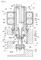
- FIG. 3 to FIG. 5 are each a cross-sectional view showing a structure and operation of the first control valve 4.
- the first control valve 4 is constituted as a motor-operated valve of stepping motor driven type and is configured by integrally assembling a valve unit 101 and a motor unit 102.
- the valve unit 101 is configured such that the proportional valve 34 of large diameter and the proportional valve 37 of large diameter are coaxially housed in a bottomed cylindrical body 104.
- the first control valve 4 is configured, as a composite valve, such that while one of the proportional valve 34 and the proportional valve 37 is being kept at a fully open state, the opening degree of the other thereof is regulated at a preset opening level.
- a lead-in port 110 is provided at one side of the body 104, whereas a first lead-out port 112 and a second lead-out port 114 are provided at the other side thereof along the vertical direction.
- the lead-in port 110 communicates with the discharge chamber of the compressor 2.
- the first lead-out port 112 communicates with the first passage 21, and the second lead-out port 114 communicates with the second passage 22. That is, a first internal passage, joining the lead-in port 110 to the first lead-out port 112, and a second internal passage, joining the lead-in port 110 to the second lead-out port 114, are formed in the body 104.
- a cylindrical partition member 116 is disposed in an upper half of the body 104.
- the partition member 116 is concentrically assembled to the body 104 through the medium of a sealing member.
- a lower end of the partition member 116 forms a valve hole 120.
- a valve seat 122 is formed by a lower-end opening end edge on the valve hole 120.
- a communication hole, which communicates the inside and the outside of the partition member 116 is provided in a surface opposite to the first lead-out port 112 in the partition member 116.
- a stepped cylindrical partition member 124 is disposed at an upper end of the body 104.
- the partition member 124 separates the interior of the valve unit 101 from the interior of the motor unit 102.
- a bearing part 126 having a circular boss shape is provided in an upper-end center of the partition member 124.
- the bearing part 126 has an internal thread on an inner circumferential surface of the bearing part 126, and an outer circumferential surface thereof functions as a sliding bearing.
- the inner circumferential surface of the partition member 124 forms a guiding passage 128, and an O-ring 130 serving as a sealing member is fitted on the lower end of the partition member 124.
- a driven member 132, a valve actuating member 134, and a transmitting member 136 are disposed coaxially inside the body 104.
- the driven member 132 which is of a stepped cylindrical shape, is disposed such that a reduced diameter portion in a central part of the driven member 132 in a direction of axis line penetrates the valve hole 120.
- the reduced diameter portion of the driven member 132 extends across the first internal passage.
- a common valve element 138 is provided at a lower end of the driven member 132, and a partition member 140 is provided at an upper end thereof. That is, the common valve element 138 is disposed in a pressure chamber that communicates with the lead-in port 110 disposed upstream of the valve hole 120.
- the partition member 140 is disposed in a position near the motor unit 102 in the first internal passage, namely in a pressure chamber that communicates with the first lead-out port 112 downstream of the valve hole 120, and the partition member 140 is slidably supported by the partition member 124.
- a plurality of legs (only one of these legs shown in FIG. 3 ), which slide along and are supported by the valve hole 144, extend in a lower end of the common valve element 138.
- the driven member 132 is configured such that a plurality of legs at the lower end of the driven member 132 slide along the valve hole 144 and such that the partition member 140 at an upper end thereof slide along the guiding passage 128. Thereby, the driven member 132 can stably operate in the direction of axis line.
- a back pressure chamber 148 is formed between the partition member 140 and the partition member 124. Also, a communication path 150, which runs through the common valve element 138 in the direction of axis line, is formed.
- a section of the common valve element 138, which forms the communication path 150, and the reduced diameter portion of the driven member 132 constitute a conduit portion. And this conduit portion communicates between the second lead-out port 114 and the back pressure chamber 148.
- the back pressure chamber 148 is constantly filled with a fluid having a downstream-side pressure Pout2 led out from the second lead-out port 114.
- an effective diameter A of the valve hole 120, an effective diameter B of the valve hole 144, and an effective diameter C of the guiding passage 128 are set equal to each other.
- C being the inside diameter of the O-ring 130
- a spring support member 152 and the transmitting member 136 are coaxially inserted inside the partition member 140 of the driven member 132.
- the spring support member 152 is of a disk shape, and the transmitting member 136 penetrates a central part of the spring support member 152.
- a spring 154 which functions as a "biasing member” is set between an upper-end opening of the partition member 140 and the spring support member 152.
- a disk-shaped spring support member 156 is inserted inside the reduced diameter portion of the driven member 132.
- a spring 158 which functions as a "biasing member” is set between the common valve element 138 and the spring support member 156.
- the valve actuating member 134 and the driven member 132 are configured such that the valve actuating member 134 and the driven member 132 can be operatively coupled or linked (operation-linked) to each other with the transmitting member 136 disposed between the valve actuating member 134 and the driven member 132. That is, an upper end of the transmitting member 136 penetrates a bottom of the valve actuating member 134, and a tip of the transmitting member 136 is swaged outwardly so as to be coupled to the valve actuating member 134.
- a stopper 160 which protrudes radially outward, is provided on a side of the transmitting member 136.
- the stopper 160 is stopped by the spring support member 152, so that the valve actuating member 134 and the driven member 132 are configured in such a manner as to move together in an upward direction. Also, a lower end of the transmitting member 136 is stopped by the spring support member 156, so that the valve actuating member 134 and the driven member 132 are configured in such a manner as to move together in a downward direction.
- the proportional valve 34 and the proportional valve 37 are open, the driven member 132 and the valve actuating member 134 are integrally displaceable in a stretched state by the biasing forces of the springs 154 and 158 (see FIG. 4 ).
- the proportional valve 34 or the proportional valve 37 is closed, the driven member 132 and the valve actuating member 134 are displaceable relative to each other in the direction of axis line (see FIG. 3 and FIG. 5 ).
- the spring loads of the springs 154 and 158 are each set so that each spring load is larger than a sliding friction, occurring between the driven member 132 and the O-ring 130, which is namely the sliding force of the driven member 132.
- the springs 154 and 158 are not compressed while the valve actuating member 134 and the driven member 132 operate together.
- the valve opening degrees of the proportional valve 34 and the proportional valve 37 can be accurately controlled.
- the valve actuating member 134 which is of a stepped cylindrical shape, has an external thread on an outer circumference of the valve actuating member 134.
- the external thread is secured to the internal thread on the bearing part 126.
- a plurality of legs 153 (four legs in the present embodiment) extending radially outward are provided at an upper end of the valve actuating member 134, and the legs 153 are fitted to a rotor of the motor unit 102.
- the valve actuating member 134 is rotated by the rotational driving force of the motor unit 102 and converts its rotative force into a translational force.
- valve actuating member 134 displaces the valve actuating member 134 in the direction of axis line through a screw mechanism that functions as a "functioning conversion mechanism".
- the common valve element 138 is driven in the direction of axis line (i.e., in an opening or closing direction of the proportional valve 34 and the proportional valve 37).
- the motor unit 102 is configured as a stepping motor that includes a rotor 172 and a stator 173.
- the motor unit 102 is configured such that the motor unit 102 supports the rotor 172 in a freely rotatable manner inside a bottomed cylindrical sleeve 170.
- the stator 173 that houses a magnetizing coil 171 therein is provided on the outer periphery of the sleeve 170.
- a lower end opening of the sleeve 170 is assembled to the body 104.
- the sleeve 170 and the body 104 constitute a body of the first control valve 4.
- the rotor 172 is comprised of a rotational shaft 174, formed in a cylindrical shape, and a magnet 176 disposed on the periphery of the rotational shaft 174.
- the magnet 176 is magnetized to 24 poles.
- An internal space extending across almost the entire length of the motor unit 102 is formed inside the rotational shaft 174.
- a guide portion 178 extending in parallel with the direction of axis line is provided at a specific position of inner circumferential surface of the rotational shaft 174.
- the guide portion 178 is used to form a raised part used to be engaged with a rotational stopper (described later).
- the guide portion 178 is constituted by a single protrusion extending in parallel with the direction of axis line.
- An elongated shaft 182 is provided, inside the rotor 172, along the axis line of the rotor 172.
- An upper end of the shaft 182 is press-fitted to a bottom center of the sleeve 170 and thereby the shaft 182 is cantilevered.
- the shaft 182 extends into an internal space in parallel with the guide portion 178.
- the shaft 182 is disposed along the same axis line as that of the valve actuating member 134.
- a guide portion 184 in the shape of a spiral, which extends across almost the entire length of the shaft 182 is formed on the shaft 182.
- the guide portion 184 which is formed of a coil-shaped material, is fitted on an exterior surface of the shaft 182.
- An upper end of the guide portion 184 is folded so as to form a stopper 186.
- a rotational stopper 188 in the shape of a spiral is rotatably engaged with the guide portion 184.
- the rotational stopper 188 has a spiral engagement portion 190, which joins with the guide portion 184, and a power-transmitting portion 192, which is supported by the rotational shaft 174.
- the engagement portion 190 has a shape of a single-turn coil, and the power-transmitting portion 192 extending radially outward is formed connectedly on a lower end of the engagement portion 190.
- a tip of the power-transmitting portion 192 is joined together with the guide portion 178. That is, the power-transmitting portion 192 abuts against a protrusion of the guide portion 178 and is stopped thereby.
- a relative displacement of the rotational stopper 188 in the rotation direction is limited by the rotational shaft 174, whereas the rotational stopper 188 slides along the guide portion 178 and the displacement thereof in the direction of axis line is permitted.
- FIG. 3 illustrates a state where the rotational stopper 188 is stopped at a bottom dead point. As the rotational stopper 188 is displaced upward and then is stopped by the stopper 186, the position at which the rotational stopper 188 stops is a top dead point.
- An upper end of the rotor 172 is freely rotatably supported by the shaft 182, whereas a lower end thereof is freely rotatably supported by the bearing part 126.
- a bottomed cylindrical end member 194 is so provided as to close and seal off an upper end opening of the rotational shaft 174, and a part of a cylindrical shaft 196 provided in a central position of the end member 194 is supported by the shaft 182. That is, the bearing part 126 serves as a bearing part at one end side, whereas a sliding portion of the shaft 182 relative to the cylindrical shaft 196 serves as a bearing part at the other end side.
- the first control valve 4 configured as described above functions as a control valve of stepping motor driven type capable of regulating the valve opening degree by controlling the drive of the motor unit 102. An operation of the first control valve 4 will be described below in detail.
- a not-shown control unit in an automotive air conditioner computes the number of steps for driving a stepping motor according to a preset opening degree and then supplies the drive current (drive pulse) to the magnetizing coil 171. Thereby, the rotor 172 rotates. Also, on one hand, the valve actuating member 134 is rotated, which in turn adjusts the opening degrees of the proportional valve 34 and the proportional valve 37 to preset openings. On the other hand, the rotational stopper 188 is driven along the guide portion 184. As a result, the operating range of each valve element is restricted.
- FIG. 3 illustrates a case where the proportional valve 34 is fully open and the proportional valve 37 is closed.
- the first control valve 4 will be in this state as indicated in FIG. 3 during a special cooling operation, for instance.
- a special cooling operation the leakage of high-temperature gaseous refrigerant discharged from the compressor 2 into the internal condenser 3 is prevented.
- FIG. 4 illustrates a case where both the proportional valve 34 and the proportional valve 37 are open.
- the first control valve 4 may possibly be in this state as indicated in FIG. 4 , depending on a situation, during a normal cooling operation, for instance. That is, as the rotor 172 is rotated and driven in one direction (in the normal direction) from the state shown in FIG. 3 , the driven member 132 is displaced in a valve opening direction of the proportional valve 37 with the result that both the proportional valve 34 and the proportional valve 37 are open as illustrated in FIG. 4 . More specifically, the valve actuating member 134, which rotates together with the rotor 172, moves to an upper position by a screw mechanism.
- FIG. 4 illustrates a state where both the proportional valve 34 and the proportional valve 37 are fully open.
- the valve opening degree of the proportional valve 37 is regulated in a manner such that the common valve element 138 is driven in a range between when the common valve element 138 is in the position shown in FIG. 3 and when it is in the position shown in FIG. 4 .
- the valve opening degree of the proportional valve 37 is regulated as described above, the fully open state of the proportional valve 34 is maintained. It is to be noted here that the "fully open state" as used herein indicates that the flow rate of refrigerant is saturated.
- FIG. 5 illustrates a case where the proportional valve 34 is closed and the proportional valve 37 is fully open.
- the first control valve 4 will be in this state during a heating operation, for instance.
- the driven member 132 is displaced in a valve closing direction of the proportional valve 34 with the result that the proportional valve 34 is closed and the proportional valve 37 is fully open as shown in FIG. 5 .
- the leakage of high-temperature gaseous refrigerant discharged from the compressor 2 into the external heat exchanger 5 is prevented.
- the proportional valve 34 can be made open when the rotor 172 is rotated and driven in the reverse direction from the state shown in FIG. 5 .
- the valve opening degree of the proportional valve 34 is regulated in a manner such that the common valve element 138 is driven in a range between when the common valve element 138 is in the position shown in FIG. 5 and when it is in the position shown in FIG. 4 .
- FIG. 5 illustrates a state where the proportional valve 34 is closed and then the rotor 172 has been rotated by a predetermined amount.
- the transmitting member 136 gets spaced apart from the spring support member 156 as shown in FIG. 5 .
- FIG. 3 illustrates a state where the proportional valve 37 is closed and then the rotor 172 has been rotated by a predetermined amount.
- the proportional valve 34 and the proportional valve 37 are both driven by the common motor unit 102; while the opening degree of one of the proportional valve 34 and the proportional valve 37 is being controlled, the other thereof is kept in a fully open state.
- the opening degree of one of those valves can be accurately controlled even though the control valves are configured as a composite valve.
- FIG. 6 is a cross-sectional view illustrating a structure according to the second embodiment.
- a driven member 232 in a body 205 is arranged such that the driven member 232 is positioned upside down as compared to the driven member 132 in the body 104 of FIG. 3 .
- the back pressure chamber 148 of the second embodiment is formed at a bottom side of the body 205 in contrast to the back pressure chamber 148 of the first embodiment formed at a top end side of the body 104 (at a motor unit 102 side).
- the guiding passage 128 of a circular hole shape is formed coaxially with the valve hole 144 at the bottom of the body 205.
- the driven member 232, the valve actuating member 134, and the transmitting member 136 are disposed coaxially inside the body 205.
- the driven member 232 is disposed such that the reduced diameter portion of the driven member 232 runs through the valve hole 144.
- the common valve element 138 is provided at an upper end of the driven member 232, and a partition member 240 is provided at a lower end thereof.
- the partition member 240 is placed in a pressure chamber that communicates with the second lead-out port 114 disposed downstream of the valve hole 144. And the partition member 240 is slidably supported by the guiding passage 128.
- the O-ring 130 which serves as a sealing member, is fitted on the outer circumferential surface of the partition member 240.
- the spring 158 which functions as a "biasing member", is set between the bottom of the body 205 and the partition member 240.
- a plurality of legs extend in an upper end of the common valve element 138.
- the driven member 232 is configured such that a plurality of legs at the upper end of the driven member 232 slide along the valve hole 120 and such that the partition member 240 at a lower end thereof slide along the guiding passage 128. Thereby, the driven member 232 can stably operate in the direction of axis line.
- a bottomed cylindrical conduit member 250 is provided in such a manner as to penetrate the common valve element 138.
- the conduit member 250 is configured such that an upper end surface of the bottom of the conduit member 250 is contactable with a lower end surface of the transmitting member 136.
- the communication path 150 which runs through the common valve element 138, is formed inside the conduit member 250.
- the conduit member 250 together with the reduced diameter portion of the driven member 132 constitutes the conduit section and communicates between the first lead-out port 112 and the back pressure chamber 148. With this structure, the back pressure chamber 148 is constantly filled with a fluid having a downstream-side pressure Pout1 led out from the first lead-out port 112.
- the effective diameter A of the valve hole 120, the effective diameter B of the valve hole 144, and the effective diameter C of the guiding passage 128 are set equal to each other.
- the effect of the refrigerant pressure acting on the common valve element 138 is cancelled.
- provision of the O-ring 130 ensures the sealing property of a sliding portion in the partition member 240 and also prevents foreign particles or the like from being trapped in the sliding portion.
- the transmitting member 136 is inserted to the bottom of the valve actuating member 134.
- the stopper 160 of the transmitting member 136 is disposed inside the valve actuating member 134.
- the stopper of the transmitting member 136 is stopped at the bottom of the valve actuating member 134, so that a downward displacement of the transmitting member 136 relative to the valve actuating member 134 (the protrusion amount of the transmitting member 136 from the valve actuating member 134) is restricted.
- the spring 154 which functions as a "biasing member", is set between an upper end of the valve actuating member 134 and the stopper 160 of the transmitting member 136.
- the spring 154 biases the stopper 160 in such a direction as to bring the stopper 160 into contact with the bottom of the valve actuating member 134.
- valve actuating member 134 and the driven member 232 are configured such that the valve actuating member 134 and the driven member 232 can be operatively coupled or linked to each other with the transmitting member 136 disposed therebetween. That is, the valve actuating member 134 moves to a lower position and is stopped by the conduit member 250, so that the valve actuating member 134 and the driven member 232 are configured in such a manner as to move together in a downward direction.
- both the proportional valve 34 and the proportional valve 37 are open, the driven member 232 and the valve actuating member 134 are integrally displaceable in a stretched state by the biasing forces of the springs 154 and 158.
- the driven member 232 and the valve actuating member 134 are displaceable relative to each other in the direction of axis line. That is, as shown in FIG. 6 , the transmitting member 136 can be spaced apart from the conduit member 250 when the proportional valve 34 is closed, and therefore the operation linkage between the valve actuating member 134 and the driven member 232 is released.
- the transmitting member 136 compresses the spring 154 with a reaction force arising from the conduit member 250. As a result, the operation linkage between the valve actuating member 134 and the driven member 232 is released.
- the net force of the spring 154 and the spring 158 is set so that the net force thereof is larger than the sliding friction between the driven member 232 and the O-ring 130 (the sliding force of the driven member 232). Also, the spring load of the spring 154 is set much larger than that of the spring 158. As a result, the spring 154 is not compressed while the valve actuating member 134 and the driven member 232 operate together. Hence, the valve opening degrees of the proportional valve 34 and the proportional valve 37 can be accurately controlled.
- the port 110 is used as a common lead-in port, into which the refrigerant is introduced, and the ports 112 and 114 are separate lead-out ports from which the refrigerants are led out.
- the ports 112 and 114 may be separate lead-in ports into which the refrigerants are introduced, respectively, and the port 110 may be used as a common lead-out port from which the refrigerant is lead out.
- the composite valve may be configured as a control valve where the flow of refrigerant is opposite to that in the above-described embodiments.
- a structure may be such that the refrigerant not at an outlet side but at an inlet side of the composite valve is led into the back pressure chamber for a pressure canceling mechanism.
- the guide portion 184 of the shaft 182 and the engagement portion 190 of the rotational stopper 188 in the motor unit 102 are each formed in the shape of a spiral and formed of a coil-shaped material.
- a screw mechanism may be provided where the guide portion 184 of the shaft 182 constitutes the external thread and the engagement portion 190 of the rotational stopper 188 constitutes the internal thread, for instance.
- a mechanism may be provided whereby the rotation is converted to the translation by both the guide portion 184 and the engagement portion 190.
- control valves are applied to an air conditioner of an electric-powered vehicle.
- the control valve according to the preferred embodiments can be applied to an air conditioner of a vehicle provided with an internal-combustion engine and an air conditioner of a hybrid vehicle equipped with both an internal-combustion engine and an electric motor drive.
- the control valve of each embodiment controls the flow of the refrigerant as a working fluid but the control valve may be configured as an electrically driven valve that controls the flow of a working fluid other than the refrigerant.
- a description has been given of an example where the stepping motor is used as the actuator but motors of other types, a solenoid or the like may be used as the actuator.
Landscapes
- Engineering & Computer Science (AREA)
- General Engineering & Computer Science (AREA)
- Mechanical Engineering (AREA)
- Physics & Mathematics (AREA)
- Thermal Sciences (AREA)
- Air-Conditioning For Vehicles (AREA)
- Electrically Driven Valve-Operating Means (AREA)
- Multiple-Way Valves (AREA)
Applications Claiming Priority (2)
| Application Number | Priority Date | Filing Date | Title |
|---|---|---|---|
| JP2011050100A JP5816874B2 (ja) | 2011-03-08 | 2011-03-08 | 制御弁 |
| PCT/JP2012/001414 WO2012120845A1 (fr) | 2011-03-08 | 2012-03-01 | Vanne de regulation |
Publications (3)
| Publication Number | Publication Date |
|---|---|
| EP2685143A1 true EP2685143A1 (fr) | 2014-01-15 |
| EP2685143A4 EP2685143A4 (fr) | 2014-09-10 |
| EP2685143B1 EP2685143B1 (fr) | 2017-05-17 |
Family
ID=46797818
Family Applications (1)
| Application Number | Title | Priority Date | Filing Date |
|---|---|---|---|
| EP12755107.5A Not-in-force EP2685143B1 (fr) | 2011-03-08 | 2012-03-01 | Vanne de regulation |
Country Status (4)
| Country | Link |
|---|---|
| EP (1) | EP2685143B1 (fr) |
| JP (1) | JP5816874B2 (fr) |
| KR (1) | KR20140008429A (fr) |
| WO (1) | WO2012120845A1 (fr) |
Cited By (2)
| Publication number | Priority date | Publication date | Assignee | Title |
|---|---|---|---|---|
| WO2020216586A1 (fr) * | 2019-04-25 | 2020-10-29 | Audi Ag | Procédé de fonctionnement d'un système de refroidissement d'un véhicule avec fonctionnement combiné d'un système de refroidissement et d'une pompe à chaleur |
| EP4264094A1 (fr) * | 2020-12-18 | 2023-10-25 | ECO Holding 1 GmbH | Ensemble vanne proportionnelle pour réfrigérant |
Families Citing this family (5)
| Publication number | Priority date | Publication date | Assignee | Title |
|---|---|---|---|---|
| JP6332945B2 (ja) * | 2013-11-14 | 2018-05-30 | 株式会社不二工機 | 流路切換弁 |
| JP6464112B2 (ja) * | 2016-04-08 | 2019-02-06 | 株式会社Soken | 統合弁装置 |
| JP6553539B2 (ja) * | 2016-04-08 | 2019-07-31 | 株式会社デンソー | 統合弁装置 |
| JP2019211014A (ja) * | 2018-06-05 | 2019-12-12 | 株式会社デンソー | 流路切替弁及び流路切替弁の製造方法 |
| JP2024032284A (ja) * | 2022-08-29 | 2024-03-12 | 愛三工業株式会社 | 弁装置 |
Family Cites Families (8)
| Publication number | Priority date | Publication date | Assignee | Title |
|---|---|---|---|---|
| US4442998A (en) * | 1979-07-24 | 1984-04-17 | Aisin Seiki Kabushiki Kaisha | Electromagnetic valve unit |
| JPS5793679U (fr) * | 1980-11-28 | 1982-06-09 | ||
| JPS6412181A (en) * | 1987-07-03 | 1989-01-17 | Matsushita Electric Industrial Co Ltd | Motor-driven three-way valve |
| JPH0482707U (fr) * | 1990-11-29 | 1992-07-17 | ||
| US5184773A (en) * | 1992-06-24 | 1993-02-09 | Siemens Automotive Limited | Pressure regulating heater control valve |
| JP3354378B2 (ja) | 1996-03-06 | 2002-12-09 | カルソニックカンセイ株式会社 | 冷暖房装置 |
| US20080042090A1 (en) * | 2006-08-18 | 2008-02-21 | Restaurant Technologies, Inc. | Piloted solenoid valve assemblies and related methods |
| JP2008232290A (ja) * | 2007-03-20 | 2008-10-02 | Saginomiya Seisakusho Inc | ニードル弁及びこのニードル弁を有する冷凍サイクル装置 |
-
2011
- 2011-03-08 JP JP2011050100A patent/JP5816874B2/ja not_active Expired - Fee Related
-
2012
- 2012-03-01 WO PCT/JP2012/001414 patent/WO2012120845A1/fr not_active Ceased
- 2012-03-01 EP EP12755107.5A patent/EP2685143B1/fr not_active Not-in-force
- 2012-03-01 KR KR1020137026265A patent/KR20140008429A/ko not_active Withdrawn
Cited By (5)
| Publication number | Priority date | Publication date | Assignee | Title |
|---|---|---|---|---|
| WO2020216586A1 (fr) * | 2019-04-25 | 2020-10-29 | Audi Ag | Procédé de fonctionnement d'un système de refroidissement d'un véhicule avec fonctionnement combiné d'un système de refroidissement et d'une pompe à chaleur |
| CN113767021A (zh) * | 2019-04-25 | 2021-12-07 | 奥迪股份公司 | 用于运行组合有制冷设备运行和热泵运行的车辆制冷设备的方法 |
| CN113767021B (zh) * | 2019-04-25 | 2024-05-03 | 奥迪股份公司 | 用于运行组合有制冷设备运行和热泵运行的车辆制冷设备的方法 |
| EP4264094A1 (fr) * | 2020-12-18 | 2023-10-25 | ECO Holding 1 GmbH | Ensemble vanne proportionnelle pour réfrigérant |
| US12498151B2 (en) | 2020-12-18 | 2025-12-16 | ECO Holding 1 GmbH | Proportional valve assembly for refrigerant |
Also Published As
| Publication number | Publication date |
|---|---|
| EP2685143A4 (fr) | 2014-09-10 |
| WO2012120845A1 (fr) | 2012-09-13 |
| JP2012184831A (ja) | 2012-09-27 |
| KR20140008429A (ko) | 2014-01-21 |
| JP5816874B2 (ja) | 2015-11-18 |
| EP2685143B1 (fr) | 2017-05-17 |
Similar Documents
| Publication | Publication Date | Title |
|---|---|---|
| EP2700853B1 (fr) | Soupape de commande | |
| EP2615341B1 (fr) | Soupape de commande entraînée par moteur pas à pas | |
| EP2685143B1 (fr) | Vanne de regulation | |
| JP5786156B2 (ja) | 車両用冷暖房装置 | |
| JP5719990B2 (ja) | 車両用冷暖房装置 | |
| JP5544469B2 (ja) | 複合弁および車両用冷暖房装置 | |
| JP5771800B2 (ja) | 制御弁 | |
| JP2012163259A (ja) | 制御弁 | |
| JP5760204B2 (ja) | 制御弁 | |
| EP2677218A1 (fr) | Soupape de commande | |
| KR20130029090A (ko) | 차량용 냉난방 장치 | |
| JP2011255689A (ja) | 車両用冷暖房装置および制御弁 | |
| JP2012136147A (ja) | 車両用冷暖房装置 | |
| JP2011225039A (ja) | 制御弁および車両用冷暖房装置 | |
| JP2012225366A (ja) | 制御弁 | |
| JP5760203B2 (ja) | 車両用冷暖房装置 | |
| JP5786157B2 (ja) | 制御弁 | |
| JP5699263B2 (ja) | 車両用冷暖房装置に用いられる制御弁 | |
| JP5786212B2 (ja) | 車両用冷暖房装置 | |
| JP2012091578A (ja) | 車両用冷暖房装置および集合弁 |
Legal Events
| Date | Code | Title | Description |
|---|---|---|---|
| PUAI | Public reference made under article 153(3) epc to a published international application that has entered the european phase |
Free format text: ORIGINAL CODE: 0009012 |
|
| 17P | Request for examination filed |
Effective date: 20130930 |
|
| AK | Designated contracting states |
Kind code of ref document: A1 Designated state(s): AL AT BE BG CH CY CZ DE DK EE ES FI FR GB GR HR HU IE IS IT LI LT LU LV MC MK MT NL NO PL PT RO RS SE SI SK SM TR |
|
| DAX | Request for extension of the european patent (deleted) | ||
| A4 | Supplementary search report drawn up and despatched |
Effective date: 20140808 |
|
| RIC1 | Information provided on ipc code assigned before grant |
Ipc: B60H 1/00 20060101ALI20140804BHEP Ipc: F16K 31/04 20060101ALI20140804BHEP Ipc: F25B 41/04 20060101ALI20140804BHEP Ipc: F16K 11/044 20060101AFI20140804BHEP |
|
| RIC1 | Information provided on ipc code assigned before grant |
Ipc: F16K 31/04 20060101ALI20161103BHEP Ipc: F25B 41/04 20060101ALI20161103BHEP Ipc: F25B 27/00 20060101ALI20161103BHEP Ipc: B60H 1/00 20060101ALI20161103BHEP Ipc: F25B 13/00 20060101ALI20161103BHEP Ipc: F16K 11/044 20060101AFI20161103BHEP |
|
| GRAP | Despatch of communication of intention to grant a patent |
Free format text: ORIGINAL CODE: EPIDOSNIGR1 |
|
| INTG | Intention to grant announced |
Effective date: 20161223 |
|
| GRAS | Grant fee paid |
Free format text: ORIGINAL CODE: EPIDOSNIGR3 |
|
| GRAA | (expected) grant |
Free format text: ORIGINAL CODE: 0009210 |
|
| AK | Designated contracting states |
Kind code of ref document: B1 Designated state(s): AL AT BE BG CH CY CZ DE DK EE ES FI FR GB GR HR HU IE IS IT LI LT LU LV MC MK MT NL NO PL PT RO RS SE SI SK SM TR |
|
| REG | Reference to a national code |
Ref country code: GB Ref legal event code: FG4D |
|
| REG | Reference to a national code |
Ref country code: CH Ref legal event code: EP |
|
| REG | Reference to a national code |
Ref country code: IE Ref legal event code: FG4D |
|
| REG | Reference to a national code |
Ref country code: AT Ref legal event code: REF Ref document number: 894776 Country of ref document: AT Kind code of ref document: T Effective date: 20170615 |
|
| REG | Reference to a national code |
Ref country code: DE Ref legal event code: R096 Ref document number: 602012032570 Country of ref document: DE |
|
| REG | Reference to a national code |
Ref country code: NL Ref legal event code: MP Effective date: 20170517 |
|
| REG | Reference to a national code |
Ref country code: LT Ref legal event code: MG4D |
|
| REG | Reference to a national code |
Ref country code: AT Ref legal event code: MK05 Ref document number: 894776 Country of ref document: AT Kind code of ref document: T Effective date: 20170517 |
|
| PG25 | Lapsed in a contracting state [announced via postgrant information from national office to epo] |
Ref country code: GR Free format text: LAPSE BECAUSE OF FAILURE TO SUBMIT A TRANSLATION OF THE DESCRIPTION OR TO PAY THE FEE WITHIN THE PRESCRIBED TIME-LIMIT Effective date: 20170818 Ref country code: ES Free format text: LAPSE BECAUSE OF FAILURE TO SUBMIT A TRANSLATION OF THE DESCRIPTION OR TO PAY THE FEE WITHIN THE PRESCRIBED TIME-LIMIT Effective date: 20170517 Ref country code: HR Free format text: LAPSE BECAUSE OF FAILURE TO SUBMIT A TRANSLATION OF THE DESCRIPTION OR TO PAY THE FEE WITHIN THE PRESCRIBED TIME-LIMIT Effective date: 20170517 Ref country code: FI Free format text: LAPSE BECAUSE OF FAILURE TO SUBMIT A TRANSLATION OF THE DESCRIPTION OR TO PAY THE FEE WITHIN THE PRESCRIBED TIME-LIMIT Effective date: 20170517 Ref country code: NO Free format text: LAPSE BECAUSE OF FAILURE TO SUBMIT A TRANSLATION OF THE DESCRIPTION OR TO PAY THE FEE WITHIN THE PRESCRIBED TIME-LIMIT Effective date: 20170817 Ref country code: LT Free format text: LAPSE BECAUSE OF FAILURE TO SUBMIT A TRANSLATION OF THE DESCRIPTION OR TO PAY THE FEE WITHIN THE PRESCRIBED TIME-LIMIT Effective date: 20170517 Ref country code: AT Free format text: LAPSE BECAUSE OF FAILURE TO SUBMIT A TRANSLATION OF THE DESCRIPTION OR TO PAY THE FEE WITHIN THE PRESCRIBED TIME-LIMIT Effective date: 20170517 |
|
| PG25 | Lapsed in a contracting state [announced via postgrant information from national office to epo] |
Ref country code: BG Free format text: LAPSE BECAUSE OF FAILURE TO SUBMIT A TRANSLATION OF THE DESCRIPTION OR TO PAY THE FEE WITHIN THE PRESCRIBED TIME-LIMIT Effective date: 20170817 Ref country code: NL Free format text: LAPSE BECAUSE OF FAILURE TO SUBMIT A TRANSLATION OF THE DESCRIPTION OR TO PAY THE FEE WITHIN THE PRESCRIBED TIME-LIMIT Effective date: 20170517 Ref country code: SE Free format text: LAPSE BECAUSE OF FAILURE TO SUBMIT A TRANSLATION OF THE DESCRIPTION OR TO PAY THE FEE WITHIN THE PRESCRIBED TIME-LIMIT Effective date: 20170517 Ref country code: PL Free format text: LAPSE BECAUSE OF FAILURE TO SUBMIT A TRANSLATION OF THE DESCRIPTION OR TO PAY THE FEE WITHIN THE PRESCRIBED TIME-LIMIT Effective date: 20170517 Ref country code: LV Free format text: LAPSE BECAUSE OF FAILURE TO SUBMIT A TRANSLATION OF THE DESCRIPTION OR TO PAY THE FEE WITHIN THE PRESCRIBED TIME-LIMIT Effective date: 20170517 Ref country code: IS Free format text: LAPSE BECAUSE OF FAILURE TO SUBMIT A TRANSLATION OF THE DESCRIPTION OR TO PAY THE FEE WITHIN THE PRESCRIBED TIME-LIMIT Effective date: 20170917 Ref country code: RS Free format text: LAPSE BECAUSE OF FAILURE TO SUBMIT A TRANSLATION OF THE DESCRIPTION OR TO PAY THE FEE WITHIN THE PRESCRIBED TIME-LIMIT Effective date: 20170517 |
|
| PG25 | Lapsed in a contracting state [announced via postgrant information from national office to epo] |
Ref country code: DK Free format text: LAPSE BECAUSE OF FAILURE TO SUBMIT A TRANSLATION OF THE DESCRIPTION OR TO PAY THE FEE WITHIN THE PRESCRIBED TIME-LIMIT Effective date: 20170517 Ref country code: RO Free format text: LAPSE BECAUSE OF FAILURE TO SUBMIT A TRANSLATION OF THE DESCRIPTION OR TO PAY THE FEE WITHIN THE PRESCRIBED TIME-LIMIT Effective date: 20170517 Ref country code: CZ Free format text: LAPSE BECAUSE OF FAILURE TO SUBMIT A TRANSLATION OF THE DESCRIPTION OR TO PAY THE FEE WITHIN THE PRESCRIBED TIME-LIMIT Effective date: 20170517 Ref country code: SK Free format text: LAPSE BECAUSE OF FAILURE TO SUBMIT A TRANSLATION OF THE DESCRIPTION OR TO PAY THE FEE WITHIN THE PRESCRIBED TIME-LIMIT Effective date: 20170517 Ref country code: EE Free format text: LAPSE BECAUSE OF FAILURE TO SUBMIT A TRANSLATION OF THE DESCRIPTION OR TO PAY THE FEE WITHIN THE PRESCRIBED TIME-LIMIT Effective date: 20170517 |
|
| REG | Reference to a national code |
Ref country code: DE Ref legal event code: R097 Ref document number: 602012032570 Country of ref document: DE |
|
| PG25 | Lapsed in a contracting state [announced via postgrant information from national office to epo] |
Ref country code: SM Free format text: LAPSE BECAUSE OF FAILURE TO SUBMIT A TRANSLATION OF THE DESCRIPTION OR TO PAY THE FEE WITHIN THE PRESCRIBED TIME-LIMIT Effective date: 20170517 Ref country code: IT Free format text: LAPSE BECAUSE OF FAILURE TO SUBMIT A TRANSLATION OF THE DESCRIPTION OR TO PAY THE FEE WITHIN THE PRESCRIBED TIME-LIMIT Effective date: 20170517 |
|
| PLBE | No opposition filed within time limit |
Free format text: ORIGINAL CODE: 0009261 |
|
| STAA | Information on the status of an ep patent application or granted ep patent |
Free format text: STATUS: NO OPPOSITION FILED WITHIN TIME LIMIT |
|
| 26N | No opposition filed |
Effective date: 20180220 |
|
| PG25 | Lapsed in a contracting state [announced via postgrant information from national office to epo] |
Ref country code: SI Free format text: LAPSE BECAUSE OF FAILURE TO SUBMIT A TRANSLATION OF THE DESCRIPTION OR TO PAY THE FEE WITHIN THE PRESCRIBED TIME-LIMIT Effective date: 20170517 |
|
| REG | Reference to a national code |
Ref country code: CH Ref legal event code: PL |
|
| GBPC | Gb: european patent ceased through non-payment of renewal fee |
Effective date: 20180301 |
|
| PG25 | Lapsed in a contracting state [announced via postgrant information from national office to epo] |
Ref country code: MC Free format text: LAPSE BECAUSE OF FAILURE TO SUBMIT A TRANSLATION OF THE DESCRIPTION OR TO PAY THE FEE WITHIN THE PRESCRIBED TIME-LIMIT Effective date: 20170517 |
|
| REG | Reference to a national code |
Ref country code: BE Ref legal event code: MM Effective date: 20180331 |
|
| REG | Reference to a national code |
Ref country code: IE Ref legal event code: MM4A |
|
| PG25 | Lapsed in a contracting state [announced via postgrant information from national office to epo] |
Ref country code: LU Free format text: LAPSE BECAUSE OF NON-PAYMENT OF DUE FEES Effective date: 20180301 |
|
| PG25 | Lapsed in a contracting state [announced via postgrant information from national office to epo] |
Ref country code: IE Free format text: LAPSE BECAUSE OF NON-PAYMENT OF DUE FEES Effective date: 20180301 |
|
| PG25 | Lapsed in a contracting state [announced via postgrant information from national office to epo] |
Ref country code: LI Free format text: LAPSE BECAUSE OF NON-PAYMENT OF DUE FEES Effective date: 20180331 Ref country code: GB Free format text: LAPSE BECAUSE OF NON-PAYMENT OF DUE FEES Effective date: 20180301 Ref country code: CH Free format text: LAPSE BECAUSE OF NON-PAYMENT OF DUE FEES Effective date: 20180331 Ref country code: BE Free format text: LAPSE BECAUSE OF NON-PAYMENT OF DUE FEES Effective date: 20180331 |
|
| PG25 | Lapsed in a contracting state [announced via postgrant information from national office to epo] |
Ref country code: FR Free format text: LAPSE BECAUSE OF NON-PAYMENT OF DUE FEES Effective date: 20180331 |
|
| PG25 | Lapsed in a contracting state [announced via postgrant information from national office to epo] |
Ref country code: MT Free format text: LAPSE BECAUSE OF NON-PAYMENT OF DUE FEES Effective date: 20180301 |
|
| PG25 | Lapsed in a contracting state [announced via postgrant information from national office to epo] |
Ref country code: TR Free format text: LAPSE BECAUSE OF FAILURE TO SUBMIT A TRANSLATION OF THE DESCRIPTION OR TO PAY THE FEE WITHIN THE PRESCRIBED TIME-LIMIT Effective date: 20170517 |
|
| PGFP | Annual fee paid to national office [announced via postgrant information from national office to epo] |
Ref country code: DE Payment date: 20200326 Year of fee payment: 9 |
|
| PG25 | Lapsed in a contracting state [announced via postgrant information from national office to epo] |
Ref country code: PT Free format text: LAPSE BECAUSE OF FAILURE TO SUBMIT A TRANSLATION OF THE DESCRIPTION OR TO PAY THE FEE WITHIN THE PRESCRIBED TIME-LIMIT Effective date: 20170517 Ref country code: HU Free format text: LAPSE BECAUSE OF FAILURE TO SUBMIT A TRANSLATION OF THE DESCRIPTION OR TO PAY THE FEE WITHIN THE PRESCRIBED TIME-LIMIT; INVALID AB INITIO Effective date: 20120301 |
|
| PG25 | Lapsed in a contracting state [announced via postgrant information from national office to epo] |
Ref country code: MK Free format text: LAPSE BECAUSE OF NON-PAYMENT OF DUE FEES Effective date: 20170517 Ref country code: CY Free format text: LAPSE BECAUSE OF FAILURE TO SUBMIT A TRANSLATION OF THE DESCRIPTION OR TO PAY THE FEE WITHIN THE PRESCRIBED TIME-LIMIT Effective date: 20170517 |
|
| PG25 | Lapsed in a contracting state [announced via postgrant information from national office to epo] |
Ref country code: AL Free format text: LAPSE BECAUSE OF FAILURE TO SUBMIT A TRANSLATION OF THE DESCRIPTION OR TO PAY THE FEE WITHIN THE PRESCRIBED TIME-LIMIT Effective date: 20170517 |
|
| REG | Reference to a national code |
Ref country code: DE Ref legal event code: R119 Ref document number: 602012032570 Country of ref document: DE |
|
| PG25 | Lapsed in a contracting state [announced via postgrant information from national office to epo] |
Ref country code: DE Free format text: LAPSE BECAUSE OF NON-PAYMENT OF DUE FEES Effective date: 20211001 |