EP2685212B1 - Système de capteur inertiel atomique à axes multiples - Google Patents
Système de capteur inertiel atomique à axes multiples Download PDFInfo
- Publication number
- EP2685212B1 EP2685212B1 EP13173669.6A EP13173669A EP2685212B1 EP 2685212 B1 EP2685212 B1 EP 2685212B1 EP 13173669 A EP13173669 A EP 13173669A EP 2685212 B1 EP2685212 B1 EP 2685212B1
- Authority
- EP
- European Patent Office
- Prior art keywords
- mems
- axis
- compensation unit
- inertial sensors
- atomic inertial
- Prior art date
- Legal status (The legal status is an assumption and is not a legal conclusion. Google has not performed a legal analysis and makes no representation as to the accuracy of the status listed.)
- Active
Links
Images


Classifications
-
- G—PHYSICS
- G01—MEASURING; TESTING
- G01N—INVESTIGATING OR ANALYSING MATERIALS BY DETERMINING THEIR CHEMICAL OR PHYSICAL PROPERTIES
- G01N21/00—Investigating or analysing materials by the use of optical means, i.e. using sub-millimetre waves, infrared, visible or ultraviolet light
- G01N21/62—Systems in which the material investigated is excited whereby it emits light or causes a change in wavelength of the incident light
- G01N21/63—Systems in which the material investigated is excited whereby it emits light or causes a change in wavelength of the incident light optically excited
- G01N21/64—Fluorescence; Phosphorescence
-
- G—PHYSICS
- G01—MEASURING; TESTING
- G01C—MEASURING DISTANCES, LEVELS OR BEARINGS; SURVEYING; NAVIGATION; GYROSCOPIC INSTRUMENTS; PHOTOGRAMMETRY OR VIDEOGRAMMETRY
- G01C19/00—Gyroscopes; Turn-sensitive devices using vibrating masses; Turn-sensitive devices without moving masses; Measuring angular rate using gyroscopic effects
- G01C19/58—Turn-sensitive devices without moving masses
-
- G—PHYSICS
- G01—MEASURING; TESTING
- G01C—MEASURING DISTANCES, LEVELS OR BEARINGS; SURVEYING; NAVIGATION; GYROSCOPIC INSTRUMENTS; PHOTOGRAMMETRY OR VIDEOGRAMMETRY
- G01C21/00—Navigation; Navigational instruments not provided for in groups G01C1/00 - G01C19/00
- G01C21/10—Navigation; Navigational instruments not provided for in groups G01C1/00 - G01C19/00 by using measurements of speed or acceleration
- G01C21/12—Navigation; Navigational instruments not provided for in groups G01C1/00 - G01C19/00 by using measurements of speed or acceleration executed aboard the object being navigated; Dead reckoning
- G01C21/16—Navigation; Navigational instruments not provided for in groups G01C1/00 - G01C19/00 by using measurements of speed or acceleration executed aboard the object being navigated; Dead reckoning by integrating acceleration or speed, i.e. inertial navigation
- G01C21/166—Mechanical, construction or arrangement details of inertial navigation systems
-
- G—PHYSICS
- G01—MEASURING; TESTING
- G01C—MEASURING DISTANCES, LEVELS OR BEARINGS; SURVEYING; NAVIGATION; GYROSCOPIC INSTRUMENTS; PHOTOGRAMMETRY OR VIDEOGRAMMETRY
- G01C21/00—Navigation; Navigational instruments not provided for in groups G01C1/00 - G01C19/00
- G01C21/10—Navigation; Navigational instruments not provided for in groups G01C1/00 - G01C19/00 by using measurements of speed or acceleration
- G01C21/12—Navigation; Navigational instruments not provided for in groups G01C1/00 - G01C19/00 by using measurements of speed or acceleration executed aboard the object being navigated; Dead reckoning
- G01C21/16—Navigation; Navigational instruments not provided for in groups G01C1/00 - G01C19/00 by using measurements of speed or acceleration executed aboard the object being navigated; Dead reckoning by integrating acceleration or speed, i.e. inertial navigation
- G01C21/183—Compensation of inertial measurements, e.g. for temperature effects
-
- G—PHYSICS
- G01—MEASURING; TESTING
- G01N—INVESTIGATING OR ANALYSING MATERIALS BY DETERMINING THEIR CHEMICAL OR PHYSICAL PROPERTIES
- G01N21/00—Investigating or analysing materials by the use of optical means, i.e. using sub-millimetre waves, infrared, visible or ultraviolet light
-
- G—PHYSICS
- G01—MEASURING; TESTING
- G01P—MEASURING LINEAR OR ANGULAR SPEED, ACCELERATION, DECELERATION, OR SHOCK; INDICATING PRESENCE, ABSENCE, OR DIRECTION, OF MOVEMENT
- G01P15/00—Measuring acceleration; Measuring deceleration; Measuring shock, i.e. sudden change of acceleration
- G01P15/02—Measuring acceleration; Measuring deceleration; Measuring shock, i.e. sudden change of acceleration by making use of inertia forces using solid seismic masses
- G01P15/08—Measuring acceleration; Measuring deceleration; Measuring shock, i.e. sudden change of acceleration by making use of inertia forces using solid seismic masses with conversion into electric or magnetic values
-
- G—PHYSICS
- G01—MEASURING; TESTING
- G01P—MEASURING LINEAR OR ANGULAR SPEED, ACCELERATION, DECELERATION, OR SHOCK; INDICATING PRESENCE, ABSENCE, OR DIRECTION, OF MOVEMENT
- G01P15/00—Measuring acceleration; Measuring deceleration; Measuring shock, i.e. sudden change of acceleration
- G01P15/18—Measuring acceleration; Measuring deceleration; Measuring shock, i.e. sudden change of acceleration in two or more dimensions
-
- G—PHYSICS
- G01—MEASURING; TESTING
- G01P—MEASURING LINEAR OR ANGULAR SPEED, ACCELERATION, DECELERATION, OR SHOCK; INDICATING PRESENCE, ABSENCE, OR DIRECTION, OF MOVEMENT
- G01P21/00—Testing or calibrating of apparatus or devices covered by the preceding groups
Definitions
- Cold atom interferometers are the basis for a newer class of inertial sensors. Analogous to the function of a fiber optic or ring laser gyroscope, inertial forces induce phase shifts in the quantum mechanical wave function of atoms traversing a loop in a cold atom interferometer.
- cold atom inertial sensors may provide a lower update rate than desirable.
- micro-electrical-mechanical systems (MEMS) inertial sensors may be used as a sort of flywheel to provide continuous output between atomic sensor readings.
- the atomic inertial sensor can be used to correct bias and scale factor drift in the MEMS inertial sensor.
- atomic inertial sensor In order to minimize size, weight, and power, it is desirable to make the atomic inertial sensor as small as possible. Unfortunately, sensitivity scales unfavorably with reduced sensor size. A minimum atomic inertial sensor volume of approximately 6 cm 3 is necessary to meet some performance metrics. However, the total volume metric for a six degree of freedom atomic inertial measurement unit (IMU) is required for some applications to be less than 20 cm 3 .
- IMU six degree of freedom atomic inertial measurement unit
- European Patent EP1896796 provides an inertial navigation system in which highly accurate inertial sensors, such as atom optic instruments are used to provide periodic corrections to a conventional navigation system to provide a continuously operating system having improved accuracy.
- An inertial sensing system comprises a first multi-axis atomic inertial sensor, a second multi-axis atomic inertial sensor, and an optical multiplexer optically coupled to the first and second multi-axis atomic inertial sensors.
- the optical multiplexer is configured to sequentially direct light along different axes of the first and second multi-axis atomic inertial sensors, while simultaneous measurements are obtained by the first and second multi-axis atomic inertial sensors along corresponding axes of the first and second multi-axis atomic inertial sensors.
- a plurality of MEMS inertial sensors is in operative communication with the first and second multi-axis atomic inertial sensors. Output signals from the first and second multi-axis atomic inertial sensors aid in correcting errors produced by the MEMS inertial sensors by sequentially updating output signals from the MEMS inertial sensors.
- Multi-axis atomic inertial sensors are provided that can be implemented in an inertial sensing system and method to aid in error correction of conventional inertial sensors.
- the multi-axis atomic inertial sensors are configured such that their sense axes can be repeatedly changed using switching optics to sequentially correct errors in the conventional inertial sensors.
- the multi-axis atomic inertial sensors can be implemented with a six degree of freedom inertial sensing system, such as an IMU, which measures acceleration and rotation in three axes.
- the outputs from the conventional inertial sensors in the IMU are disciplined to the atomic inertial sensors such that much of the bias and scale factor errors are removed from the conventional inertial sensors.
- MEMS inertial sensors Although the use of MEMS inertial sensors is described in various embodiments as follows, other conventional inertial sensors can be fused with the multi-axis atomic inertial sensors in a similar fashion.
- the inertial sensing system comprises a pair of multi-axis atomic inertial sensors, and an optical multiplexer operatively coupled to the multi-axis atomic inertial sensors.
- the optical multiplexer includes a plurality of optical switches configured to sequentially direct light along different axes of the first and second multi-axis atomic inertial sensors.
- a plurality of MEMS inertial sensors such as six MEMS inertial sensors (e.g., three MEMS gyroscopes and three MEMS accelerometers), is in operative communication with the multi-axis atomic inertial sensors.
- Output signals from the multi-axis atomic inertial sensors aid in correcting errors produced by the MEMS inertial sensors by sequentially updating the output signals of the MEMS inertial sensors.
- cycle time for each atomic sensor is about 20 ms. Approximately 10 ms is required to prepare a sample of cold atoms, and approximately another 10 ms to interrogate the atoms to extract inertial information. It should be noted that these times are parameters that can be varied depending on performance tradeoffs, such as bandwidth versus sensitivity.
- Acceleration and rotation are entangled in each measurement, so simultaneous measurements of reciprocal atomic sensors are required to separate acceleration from rotation. A minimum of two atomic sensor bodies are therefore needed.
- the truth measurement of rotation and acceleration obtained by the pair of atomic sensors is compared to the output of the appropriate MEMS sensor set, and a calibration correction is made.
- the next measurement by the atomic sensor pair may be along the same axis, or along a different axis depending on priorities for MEMS sensor correction. If a different sense axis is desired, then laser optics are switched in order to interrogate the atoms along a different axis.
- multiplexing results in a reduction of about three in atomic sensor duty cycle, from about 20% (six atomic sensors without multiplexing) to about 6.7% (two atomic sensors with multiplexing). In other implementations, faster cycle times are possible, depending on desired performance.
- the axis of laser light can be continuously blended to create a an optical gimbal sensor.
- the sense axis for the atomic sensor can be rotated continuously to maintain an orientation along, for instance, the principle axis of rotation, or the net acceleration vector, or any other desired orientation.
- the optical gimbal function provides the capability of continuously rotating the input axes of the gyroscope to maintain alignment with an arbitrary axis.
- Atomic sensor sensitivity scales inversely with dynamic range, and this tradeoff can be adjusted in real time.
- Adjustments to the sense axis orientations can take advantage of this capability by intelligently choosing how to split the rotation among the gyroscope triad sense axis. This can be used, for instance, to align one gyroscope axis of the triad with the principal axis of rotation. This maximizes the signal on that gyroscope, and minimizes the signal on the gyroscopes orthogonal to the axis of rotation.
- the sense axes can be arranged such that the rotation signal is "split" evenly among the sense axes, ensuring that no single axis will require an excessive dynamic range (and corresponding decreased sensitivity).
- the present approach achieves low size, weight, and power by extracting six degrees of inertial freedom from a single pair of atomic inertial sensors. This is accomplished by using an optical multiplexer, which drives the optical switches in selecting specific axes along which to apply laser light when manipulating the atoms in the atomic sensor pair.
- the switching function determines the orientation of laser light within the sensor package. Changing orientation of the laser light changes the sense axis for the atomic sensor.
- FIG. 1 is a block diagram of an inertial sensing system 100, such as for an IMU, which employs multi-axis atomic inertial sensors according to one embodiment.
- the sensing system 100 includes a pair of multi-axis atomic inertial sensors, including a first atomic inertial sensor 102 and a second atomic inertial sensor 104, as well as a plurality of MEMS inertial sensors, such as at least one MEMS gyroscope 106 and at least one MEMS accelerometer 108.
- each sensor can act as both an accelerometer and a gyroscope in detecting acceleration and rotation.
- the two atomic inertial sensors are required in order to distinguish how much phase shift is due to acceleration and how much is due to rotation.
- These sensors are operated in reciprocal fashion leading to a sign change for rotation but not for acceleration. This allows the atomic inertial sensors to distinguish how much phase shift is due to acceleration and how much is due to rotation.
- one of the atomic inertial sensors is sensitive to both acceleration and rotation, and the other sensor is sensitive only to acceleration.
- the atomic inertial sensors and the MEMS inertial sensors operatively communicate with each other through a closed loop feedback unit 110. Further details of a MEMS/atomic closed feedback loop are described in U.S. Provisional Application No. 61/665,061 (Attorney Docket No. H0034858), filed on June 27, 2012, entitled CLOSED LOOP ATOMIC INERTIAL SENSOR.
- the inertial sensing system 100 also includes an optical multiplexer 114 in operative communication with atomic inertial sensors 102 and 104.
- the optical multiplexer is described in further detail hereafter with respect to Figure 2 .
- An output signal from atomic inertial sensor 102 is sent to an atomic inertial sensor compensation unit 118, and an output signal from atomic inertial sensor 104 is sent to an atomic inertial sensor compensation unit 120.
- the compensation units 118 and 120 provide sensor corrections based on a factory calibration.
- An output signal from MEMS gyroscope 106 is sent to a MEMS gyroscope compensation unit 122, and an output signal from MEMS accelerometer 108 is sent to a MEMS accelerometer compensation unit 124.
- the compensation units 122 and 124 provide for error correction of the MEMS inertial sensors.
- the fusion algorithm 128 outputs a feedback signal to MEMS compensation units 122 and 124 to provide for error correction.
- errors in the MEMS inertial sensor outputs can be estimated and corrected using the fusion algorithm 128.
- the output signal from MEMS gyroscope compensation unit 122 can be optionally sent to a coning module 132 and a sculling module 134 for applying high speed corrections to output signals of MEMS gyroscope 106.
- a corrected signal is sent from coning module 132 to an adder 136, which also receives the original signal from compensation unit 122 and outputs a delta theta ( ⁇ ) signal.
- a corrected signal is sent from sculling module 134 to an adder 138, which also receives the original signal from compensation unit 124 and outputs a delta velocity (v) signal.
- the output signal from MEMS accelerometer compensation unit 124 can be optionally sent to sculling module 134 for applying high speed corrections to output signals of MEMS accelerometer 108.
- a corrected signal is sent from sculling module 134 to an adder 138, which also receives the original signal from compensation unit 124 and outputs a delta velocity (v) signal.
- FIG. 2 is a block diagram of a multi-axis atomic inertial sensor apparatus 200 according to one embodiment.
- the sensor apparatus 200 includes a plurality of laser devices, such as a first laser device 202, which can be a distributed Bragg reflector (DBR), and a second laser device 204, which can also be a DBR.
- DBR distributed Bragg reflector
- VCSEL vertical-cavity surface-emitting laser
- the laser devices 202 and 204 can be frequency locked to a vapor cell of an atomic sensor by saturated absorption spectroscopy 205 or an etalon 206.
- the laser devices 202 and 204 are in optical communication with an optical multiplexer 210 through various optical components, such as one or more lenses 207, optical isolators 208, beam splitters 209, and the like.
- Saturated absorption can be used to lock laser device 202 to an atomic transition.
- the laser light shines through the vapor cell, and is retro-reflected back onto the same beam path.
- This technique selects only zero velocity atoms for interaction with the light. Doppler broadening of the atomic transition is therefore eliminated, resulting in a very narrow absorption line that is detected by a photodetector 211.
- the narrow absorption line allows for precise and stable locking of the laser frequency.
- phase lock laser devices 202 and 204 For bichromatic transitions, it is desirable to phase lock laser devices 202 and 204 so that they provide a coherent electromagnetic field to the atoms in the vapor cell.
- One technique for phase locking laser devices 202 and 204 is to shine both of their laser beams onto a common photodetector 213, where the beams interfere with one another.
- the laser devices 202 and 204 can differ in frequency by a few GHz. The frequency difference modulates the laser interference at a few GHz, resulting in a radio-frequency (RF) output signal from photodetector 213 of a few GHz. This RF signal is then compared to a stable RF reference signal.
- RF radio-frequency
- one laser device is the master and the other laser device is the slave.
- two slave lasers can be locked to a single master laser, which affords greater flexibility in the range over which both slave lasers can be locked.
- the multiplexer 210 includes a plurality of optical components, such as a plurality of beam splitters 212 and reflectors 214, which are configured to direct a light beam having a first frequency (f1) from laser device 202 and a light beam having a second frequency (f2) from laser device 204 to various optical switches that are coupled to a pair of atomic inertial sensors 230 and 232.
- the Raman frequency (f1-f2) is about a few GHz, corresponding to the hyperfine splitting of an alkali atom, such as rubidium (6.8 GHz) or cesium (9.2 GHz).
- the Bragg/Bloch frequency (f1-f2) is about 10 kHz and can be ramped to induce absorption of multiple quanta of photon momenta, to enhance sensor scale factor.
- a first set of optical switches 222-1, 222-2, and 222-3 in multiplexer 210 are configured to sequentially direct the light beams along different orientation axes A-1, A-2, and A-3 (e.g., x, y, z axes) to atomic sensor 230.
- a second set of optical switches 224-1, 224-2, and 224-3 are configured to sequentially direct laser light along different orientation axes B-1, B-2, and B-3 (e.g., x, y, z axes) to atomic sensor 232.
- an optical fiber 240 can be coupled to the output of each of the optical switches to direct laser light to respective inputs of atomic sensors 230 and 232.
- the optical switches switch on different axes or combinations of axes to make the atomic sensors sensitive to acceleration or rotation along different axes.
- atomic sensors 230 and 232 sequentially measure motion with respect to all three coordinate axes by selecting light beam pairs that are oriented orthogonal (rotation) and parallel (acceleration) to those axes.
- atomic sensors 230 and 232 each comprise a magneto-optical trap (MOT) 242, and sensor heads 244 that include a photodetector (PD), a mirror, and a waveplate, which are aligned with the beams input into the atomic sensors.
- MOT magneto-optical trap
- PD photodetector
- PD photodetector
- waveplate a waveplate
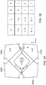
- Figure 3A shows an exemplary interferometer trajectory in a multi-axis atomic inertial sensor according to one embodiment, which utilizes a moving Bragg lattice for feedback.
- the interferometer in the atomic inertial sensor is created by two pairs of counter-propagating beams 310a, 310b and 320a, 320b, which intersect atoms in the sensor.
- the wave vectors (k) of the beams determine the trajectory of the atoms, and therefore the axes of sensitivity for acceleration ( a ) and rotation ( ⁇ ).
- Possible combinations of laser orientations, with corresponding axes of sensitivity are shown in the table of Figure 3B .
- the laser light is applied along two wave vectors.
- the table in Figure 3B tabulates the three possible pairings of wave vectors, along with the corresponding axes of rotation and acceleration.
- the pair of beams divides the quantum mechanical wave function of each of the laser cooled atoms, so that there is a 50% probability of finding the atom either above or below the axis of separation.
- Modulation of laser frequency and amplitude guides each half of the wave function along the trajectory shown in Figure 3A .
- the quantum mechanical phase of the atom has acquired a phase shift that is proportional to rotation and acceleration. This phase shift can be read out by subsequent imaging of cloud position and/or internal state detection.
Landscapes
- Engineering & Computer Science (AREA)
- Radar, Positioning & Navigation (AREA)
- Remote Sensing (AREA)
- Physics & Mathematics (AREA)
- General Physics & Mathematics (AREA)
- Automation & Control Theory (AREA)
- Health & Medical Sciences (AREA)
- Chemical & Material Sciences (AREA)
- Life Sciences & Earth Sciences (AREA)
- Analytical Chemistry (AREA)
- Biochemistry (AREA)
- General Health & Medical Sciences (AREA)
- Immunology (AREA)
- Pathology (AREA)
- Nuclear Medicine, Radiotherapy & Molecular Imaging (AREA)
- Gyroscopes (AREA)
- Navigation (AREA)
Claims (11)
- Système de détection inertielle (100), comprenant :un premier capteur inertiel atomique multiaxe (102, 230) ;un deuxième capteur inertiel atomique multiaxe (104, 232) ;un multiplexeur optique (114, 210) optiquement couplé aux premier et deuxième capteurs inertiels atomiques multiaxes, le multiplexeur optique configuré pour diriger successivement de la lumière le long de différents axes des premier et deuxième capteurs inertiels atomiques multiaxes, de telle sorte que des mesures simultanées sont obtenues le long d'axes correspondants des premier et deuxième capteurs inertiels atomiques multiaxes ; etune pluralité de capteurs inertiels à systèmes microélectromécaniques (MEMS) (106, 108) en communication fonctionnelle avec les premier et deuxième capteurs inertiels atomiques multiaxes ;dans lequel des signaux de sortie des premier et deuxième capteurs inertiels atomiques multiaxes aident à corriger des erreurs produites par les capteurs inertiels MEMS en actualisant successivement des signaux de sortie des capteurs inertiels MEMS.
- Système de la revendication 1, dans lequel le premier capteur inertiel atomique multiaxe est configuré pour détecter une accélération et une rotation.
- Système de la revendication 2, dans lequel le deuxième capteur inertiel atomique multiaxe est configuré pour détecter une accélération et une rotation.
- Système de la revendication 2, dans lequel le deuxième capteur inertiel atomique multiaxe est configuré pour détecter uniquement une accélération.
- Système de la revendication 1, dans lequel les capteurs inertiels MEMS comprennent au moins un gyroscope MEMS (106) et au moins un accéléromètre MEMS (108) .
- Système de la revendication 1, dans lequel les capteurs inertiels MEMS sont configurés pour communiquer fonctionnellement avec les premier et deuxième capteurs inertiels atomiques multiaxes par un asservissement en boucle fermée (110).
- Système de la revendication 5, comprenant en outre :une première unité de compensation de capteur inertiel atomique (118) qui est configurée pour recevoir un signal de sortie du premier capteur inertiel atomique multiaxe, la première unité de compensation de capteur inertiel atomique étant configurée pour apporter des corrections de capteur basées sur un étalonnage d'usine ;une deuxième unité de compensation de capteur inertiel atomique (120) qui est configurée pour recevoir un signal de sortie du deuxième capteur inertiel atomique multiaxe, la deuxième unité de compensation de capteur inertiel atomique apportant des corrections de capteur basées sur un étalonnage d'usine ;une unité de compensation de gyroscope MEMS (122) qui est configurée pour recevoir un signal de sortie du gyroscope MEMS, l'unité de compensation de gyroscope MEMS aidant à corriger des erreurs produites par le gyroscope MEMS ; etune unité de compensation d'accéléromètre MEMS (124) qui est configurée pour recevoir un signal de sortie de l'accéléromètre MEMS, l'unité de compensation d'accéléromètre MEMS aidant à corriger des erreurs produites par l'accéléromètre MEMS.
- Système de la revendication 7, comprenant en outre un filtre de fusion (128) qui est configuré pour recevoir des signaux de sortie provenant à la fois de la première unité de compensation de capteur inertiel atomique, de la deuxième unité de compensation de capteur inertiel atomique, de l'unité de compensation de gyroscope MEMS, et de l'unité de compensation d'accéléromètre MEMS, le filtre de fusion étant configuré pour délivrer un signal d'asservissement à l'unité de compensation de gyroscope MEMS et à l'unité de compensation d'accéléromètre MEMS pour aider à la correction d'erreurs du gyroscope MEMS et de l'accéléromètre MEMS.
- Système de la revendication 1, dans lequel le multiplexeur optique est en communication optique avec un premier dispositif laser (202) qui est configuré pour délivrer un faisceau lumineux ayant une première fréquence, et un deuxième dispositif laser (204) qui est configuré pour délivrer un faisceau lumineux ayant une deuxième fréquence.
- Système de la revendication 9, le système étant configuré comme un système de détection optique à cardan.
- Procédé de détection inertielle, le procédé comprenant les étapes suivantes :se procurer un premier capteur inertiel atomique multiaxe et un deuxième capteur inertiel atomique multiaxe ;transmettre une paire de faisceaux laser à travers un multiplexeur optique qui dirige successivement les faisceaux laser le long de différents axes des premier et deuxième capteurs inertiels atomiques multiaxes, de telle sorte que des mesures simultanées sont obtenues le long d'axes correspondants des premier et deuxième capteurs inertiels atomiques multiaxes ; etdélivrer des signaux depuis les premier et deuxième capteurs inertiels atomiques multiaxes pour aider à corriger des erreurs produites par un ou plusieurs capteurs inertiels à systèmes microélectromécaniques (MEMS) en actualisant successivement des signaux de sortie des capteurs inertiels MEMS.
Priority Applications (1)
| Application Number | Priority Date | Filing Date | Title |
|---|---|---|---|
| EP18154075.8A EP3333543B1 (fr) | 2012-07-12 | 2013-06-25 | Système de capteur inertiel atomique à axes multiples |
Applications Claiming Priority (2)
| Application Number | Priority Date | Filing Date | Title |
|---|---|---|---|
| US201261670797P | 2012-07-12 | 2012-07-12 | |
| US13/661,809 US8860933B2 (en) | 2012-07-12 | 2012-10-26 | Multi-axis atomic inertial sensor system |
Related Child Applications (2)
| Application Number | Title | Priority Date | Filing Date |
|---|---|---|---|
| EP18154075.8A Division-Into EP3333543B1 (fr) | 2012-07-12 | 2013-06-25 | Système de capteur inertiel atomique à axes multiples |
| EP18154075.8A Division EP3333543B1 (fr) | 2012-07-12 | 2013-06-25 | Système de capteur inertiel atomique à axes multiples |
Publications (3)
| Publication Number | Publication Date |
|---|---|
| EP2685212A2 EP2685212A2 (fr) | 2014-01-15 |
| EP2685212A3 EP2685212A3 (fr) | 2016-01-06 |
| EP2685212B1 true EP2685212B1 (fr) | 2018-05-02 |
Family
ID=48672481
Family Applications (2)
| Application Number | Title | Priority Date | Filing Date |
|---|---|---|---|
| EP18154075.8A Active EP3333543B1 (fr) | 2012-07-12 | 2013-06-25 | Système de capteur inertiel atomique à axes multiples |
| EP13173669.6A Active EP2685212B1 (fr) | 2012-07-12 | 2013-06-25 | Système de capteur inertiel atomique à axes multiples |
Family Applications Before (1)
| Application Number | Title | Priority Date | Filing Date |
|---|---|---|---|
| EP18154075.8A Active EP3333543B1 (fr) | 2012-07-12 | 2013-06-25 | Système de capteur inertiel atomique à axes multiples |
Country Status (4)
| Country | Link |
|---|---|
| US (1) | US8860933B2 (fr) |
| EP (2) | EP3333543B1 (fr) |
| JP (1) | JP2014021107A (fr) |
| CN (1) | CN103542850A (fr) |
Families Citing this family (34)
| Publication number | Priority date | Publication date | Assignee | Title |
|---|---|---|---|---|
| US9030655B2 (en) | 2012-06-27 | 2015-05-12 | Honeywell International Inc. | Closed loop atomic inertial sensor |
| US9568316B2 (en) * | 2013-03-15 | 2017-02-14 | The Charles Stark Draper Laboratory, Inc. | Ring architecture for sequential operation of an atomic gyroscope |
| US9086429B1 (en) * | 2013-05-29 | 2015-07-21 | Sandia Corporation | High data rate atom interferometric device |
| US20150358522A1 (en) * | 2014-03-31 | 2015-12-10 | Goodrich Corporation | Stabilization Of Gyro Drift Compensation For Image Capture Device |
| DE102014211177A1 (de) * | 2014-06-11 | 2015-12-17 | Continental Teves Ag & Co. Ohg | Verfahren und System zur echtzeitfähigen Bereitstellung von dynamischen Fehlerwerten dynamischer Messwerte |
| US9175960B1 (en) | 2014-09-10 | 2015-11-03 | Honeywell International Inc. | Optically dithered atomic gyro-compass |
| US9897448B2 (en) | 2014-10-31 | 2018-02-20 | The Charles Stark Draper Laboratory, Inc. | Systems and methods for multiple species atom interferometry |
| CN104457760B (zh) * | 2014-11-05 | 2017-08-29 | 上海卫星工程研究所 | 高分辨率光栅型光谱导航仪设计系统及其设计方法 |
| US10330697B2 (en) | 2015-05-15 | 2019-06-25 | Honeywell International Inc. | Active, in-situ, calibration of MEMS accelerometers using optical forces |
| US9874581B2 (en) * | 2015-05-15 | 2018-01-23 | Honeywell International Inc. | In-situ bias correction for MEMS accelerometers |
| US9983225B2 (en) | 2015-06-29 | 2018-05-29 | Honeywell International Inc. | Optical-mechanical vibrating beam accelerometer |
| US10371763B2 (en) * | 2015-07-17 | 2019-08-06 | Honeywell International Inc. | Systems and methods for low power magnetic field generation for atomic sensors using electro-permanent magnets |
| FR3044398B1 (fr) * | 2015-11-27 | 2019-07-19 | Thales | Source laser pour capteur inertiel a atomes froids |
| US10352702B2 (en) | 2016-09-02 | 2019-07-16 | Honeywell International Inc. | Fully reciprocal atomic interferometric gyroscope |
| FR3060114B1 (fr) * | 2016-12-13 | 2019-05-17 | Commissariat A L'energie Atomique Et Aux Energies Alternatives | Procede d'aide a la navigation, produit programme d'ordinateur et centrale de navigation inertielle associes |
| FR3063141B1 (fr) * | 2017-02-23 | 2021-02-12 | Ixblue | Systeme et procede hybride de mesure inertielle base sur un interferometre a atomes froids et a impulsions lumineuses |
| CN109269501B (zh) * | 2017-07-18 | 2021-03-30 | 清华大学 | 冷原子干涉惯性测量系统 |
| WO2019134755A1 (fr) * | 2018-01-08 | 2019-07-11 | Siemens Aktiengesellschaft | Dispositif à capteurs multiaxiaux |
| FR3087883B1 (fr) * | 2018-10-26 | 2021-02-12 | Ixblue | Systeme et procede d'interferometre atomique multi-axes |
| CN113272657B (zh) * | 2019-01-24 | 2024-09-13 | 乌第有限合伙公司 | 基于粒子的加速度计 |
| US11800629B2 (en) | 2019-02-26 | 2023-10-24 | Nippon Telegraph And Telephone Corporation | Magneto-optical trap method and apparatus using positive and negative g-factors |
| WO2020249974A1 (fr) * | 2019-06-13 | 2020-12-17 | The University Of Nottingham | Gravimètres et gradiomètres quantiques |
| CN110631580B (zh) * | 2019-08-22 | 2021-10-01 | 北京航天控制仪器研究所 | 一种基于原子自旋陀螺仪的单轴惯性平台系统 |
| US11187530B2 (en) | 2019-10-07 | 2021-11-30 | Honeywell International Inc. | Optical gimbal |
| US11255672B2 (en) * | 2019-10-28 | 2022-02-22 | Honeywell International Inc. | System having an extended life high performance sensor |
| CN112179341B (zh) * | 2020-08-24 | 2022-04-19 | 北京航天时代光电科技有限公司 | 一种宇航用三轴一体光子晶体光纤陀螺惯性测量装置 |
| US12038285B1 (en) * | 2020-08-31 | 2024-07-16 | National Technology & Engineering Solutions Of Sandia, Llc | Hybrid inertial navigation system and method |
| JP6948656B1 (ja) * | 2020-10-08 | 2021-10-13 | 日本航空電子工業株式会社 | 慣性センサ、原子干渉計、原子の速さを調整する方法、原子の速さを調整する装置 |
| US12228408B2 (en) | 2020-11-06 | 2025-02-18 | The Boeing Company | Sensor data fusion system with noise reduction and fault protection |
| CN113514047B (zh) * | 2021-06-04 | 2022-12-27 | 北京航天时代光电科技有限公司 | 一种小型轻质化宇航用三轴陀螺组合 |
| CN114413873B (zh) * | 2021-12-10 | 2023-04-21 | 华中光电技术研究所(中国船舶重工集团公司第七一七研究所) | 一种基于原子陀螺的惯性测量装置及其安装方法 |
| JP7771737B2 (ja) * | 2021-12-24 | 2025-11-18 | セイコーエプソン株式会社 | 慣性センサー装置 |
| US20230360817A1 (en) * | 2022-05-04 | 2023-11-09 | Government Of The United States Of America, As Represented By The Secretary Of Commerce | Photonically Multiplexed Optical Measurement Apparatus and Performing Optical Multiplexing |
| US12359919B2 (en) | 2023-03-28 | 2025-07-15 | Honeywell International Inc. | High-contrast atomic inertial interferometry with frequency comb or comb-like light source |
Family Cites Families (22)
| Publication number | Priority date | Publication date | Assignee | Title |
|---|---|---|---|---|
| US3761721A (en) | 1972-07-06 | 1973-09-25 | Trw Inc | Matter wave interferometric apparatus |
| US4992656A (en) | 1987-10-26 | 1991-02-12 | Clauser John F | Rotation, acceleration, and gravity sensors using quantum-mechanical matter-wave interferometry with neutral atoms and molecules |
| US5052808A (en) | 1990-02-15 | 1991-10-01 | Litton Systems, Inc. | Method and apparatus for interferometric rotation sensor phase modulation, intensity demodulation, and control |
| FR2675900B1 (fr) | 1991-04-26 | 1995-12-01 | Alsthom Cge Alcatel | Capteur de vibrations a fibre optique et accelerometre utilisant un tel capteur. |
| US5274231A (en) | 1992-04-14 | 1993-12-28 | Board Of Trustees, Leland Stanford Jr. University | Method and apparatus for manipulating atoms, ions or molecules and for measuring physical quantities using stimulated Raman transitions |
| US6647352B1 (en) * | 1998-06-05 | 2003-11-11 | Crossbow Technology | Dynamic attitude measurement method and apparatus |
| US6456939B1 (en) | 2000-01-04 | 2002-09-24 | Mccall Hiram | Micro inertial measurement unit |
| DE10031542B4 (de) | 2000-06-28 | 2005-02-17 | Eads Astrium Gmbh | Inertialsensor zur Lagerung und Kontrolle einer Inertialreferenz in einem Satelliten |
| US6697736B2 (en) * | 2002-02-06 | 2004-02-24 | American Gnc Corporation | Positioning and navigation method and system thereof |
| US7333112B2 (en) * | 2003-05-14 | 2008-02-19 | Pixar | Rig baking |
| US7142983B2 (en) * | 2003-07-03 | 2006-11-28 | Northrop Grumman Corporation | Method for the processing of non-continuous atom interferometer intertial instrument measurements and continuous wide bandwidth instrument measurements with a gravity database |
| US7248964B2 (en) * | 2003-12-05 | 2007-07-24 | Honeywell International Inc. | System and method for using multiple aiding sensors in a deeply integrated navigation system |
| US7317184B2 (en) * | 2005-02-01 | 2008-01-08 | The Board Of Trustees Of The Leland Stanford Junior University | Kinematic sensors employing atom interferometer phases |
| US20210293543A1 (en) | 2005-06-22 | 2021-09-23 | James R. Huddle | Apparatus and Method for Integrating Continuous and Discontinuous Inertial Instrument |
| US7728587B2 (en) * | 2007-07-31 | 2010-06-01 | Northrop Grumman Guidance And Electronics Company, Inc. | Self-calibrating nuclear magnetic resonance gyro |
| US7667644B2 (en) * | 2007-10-09 | 2010-02-23 | Honeywell International Inc. | GPS receiver RAIM with slaved precision clock |
| US7995630B2 (en) | 2008-04-01 | 2011-08-09 | Rakuljic George A | High performance tunable lasers utilizing optical phase-locked loops |
| US7847924B2 (en) | 2008-12-17 | 2010-12-07 | Lockheed Martin Corporation | Performance of an atom interferometric device through complementary filtering |
| IT1397594B1 (it) * | 2009-12-21 | 2013-01-16 | St Microelectronics Rousset | Giroscopio microelettromeccanico con funzione di auto-test continua e metodo di controllo di un giroscopio microelettromeccanico. |
| US8583371B1 (en) * | 2010-12-23 | 2013-11-12 | Lockheed Martin Corporation | Autonomous gyro temperature calibration |
| US9470707B2 (en) | 2012-02-17 | 2016-10-18 | Honeywell International Inc. | Atom interferometer with adaptive launch direction and/or position |
| US9030655B2 (en) | 2012-06-27 | 2015-05-12 | Honeywell International Inc. | Closed loop atomic inertial sensor |
-
2012
- 2012-10-26 US US13/661,809 patent/US8860933B2/en active Active
-
2013
- 2013-06-25 EP EP18154075.8A patent/EP3333543B1/fr active Active
- 2013-06-25 EP EP13173669.6A patent/EP2685212B1/fr active Active
- 2013-07-04 JP JP2013140759A patent/JP2014021107A/ja not_active Ceased
- 2013-07-11 CN CN201310290333.8A patent/CN103542850A/zh active Pending
Non-Patent Citations (1)
| Title |
|---|
| None * |
Also Published As
| Publication number | Publication date |
|---|---|
| EP2685212A2 (fr) | 2014-01-15 |
| JP2014021107A (ja) | 2014-02-03 |
| EP2685212A3 (fr) | 2016-01-06 |
| CN103542850A (zh) | 2014-01-29 |
| US20140016118A1 (en) | 2014-01-16 |
| US8860933B2 (en) | 2014-10-14 |
| EP3333543A1 (fr) | 2018-06-13 |
| EP3333543B1 (fr) | 2019-05-29 |
Similar Documents
| Publication | Publication Date | Title |
|---|---|---|
| EP3333543B1 (fr) | Système de capteur inertiel atomique à axes multiples | |
| EP2679953B1 (fr) | Capteur inertiel atomique en boucle fermée | |
| US11175139B2 (en) | Hybrid inertial measurement system and method using a light pulse cold atom interferometer | |
| EP3112879B1 (fr) | Accéléromètre à bras vibrant opto-mécanique | |
| US9897448B2 (en) | Systems and methods for multiple species atom interferometry | |
| EP3290862B1 (fr) | Gyroscope interférométrique atomique entièrement réciproque | |
| JP2014525027A (ja) | 原子線ジャイロスコープ | |
| US20160298967A1 (en) | Ring architecture for sequential operation of an atomic gyroscope | |
| EP3875903B1 (fr) | Système de résonance d'hyperfréquences à transport optique bidirectionnel basé sur une structure de circulateur et procédé de détection de vitesse angulaire par ledit système | |
| US20170370840A1 (en) | Separated Parallel Beam Generation for Atom Interferometry | |
| CN114353790B (zh) | 原子干涉惯性导航信息探测系统及探测方法 | |
| US9175960B1 (en) | Optically dithered atomic gyro-compass | |
| CN111238464B (zh) | 基于互易性调制与时分切换的谐振式光学陀螺的检测方法 | |
| Hiller et al. | Noise contributions in a closed-loop MEMS gyroscope for automotive applications | |
| US11378401B2 (en) | Polarization-maintaining fully-reciprocal bi-directional optical carrier microwave resonance system and angular velocity measurement method thereof | |
| EP3652500B1 (fr) | Capteur inertiel à mode galerie à écho et procédé associé | |
| US20080285046A1 (en) | System and method for improving the resolution of an optical fiber gyroscope and a ring laser gyroscope | |
| WO2023055566A1 (fr) | Filtrage d'espace de phase dans des capteurs inertiels à faisceaux thermiques | |
| Li et al. | IFOG based on rhombic optical path difference bias configuration for high-frequency angular vibration measurement | |
| Armenise et al. | Gyroscope technologies for space applications | |
| AU2023248639A1 (en) | Cold-atom and light-pulse interferometric system and method, for the on-board measurement of acceleration or rotation | |
| US10386187B1 (en) | Rotation and acceleration sensor based on nondegenerate ring lasers | |
| Chung et al. | Cubesat compatible fiber-optic gyroscope | |
| de Castanet | Interféromètre atomique en rotation pour l'accélérométrie quantique embarquée | |
| Raj et al. | A Non Linear Dynamics and Control in Ring Laser Gyroscope for Missile Guidance and Control System |
Legal Events
| Date | Code | Title | Description |
|---|---|---|---|
| PUAI | Public reference made under article 153(3) epc to a published international application that has entered the european phase |
Free format text: ORIGINAL CODE: 0009012 |
|
| 17P | Request for examination filed |
Effective date: 20130625 |
|
| AK | Designated contracting states |
Kind code of ref document: A2 Designated state(s): AL AT BE BG CH CY CZ DE DK EE ES FI FR GB GR HR HU IE IS IT LI LT LU LV MC MK MT NL NO PL PT RO RS SE SI SK SM TR |
|
| AX | Request for extension of the european patent |
Extension state: BA ME |
|
| PUAL | Search report despatched |
Free format text: ORIGINAL CODE: 0009013 |
|
| RAP1 | Party data changed (applicant data changed or rights of an application transferred) |
Owner name: HONEYWELL INTERNATIONAL INC. |
|
| AK | Designated contracting states |
Kind code of ref document: A3 Designated state(s): AL AT BE BG CH CY CZ DE DK EE ES FI FR GB GR HR HU IE IS IT LI LT LU LV MC MK MT NL NO PL PT RO RS SE SI SK SM TR |
|
| AX | Request for extension of the european patent |
Extension state: BA ME |
|
| RIC1 | Information provided on ipc code assigned before grant |
Ipc: G01C 19/58 20060101AFI20151130BHEP Ipc: G01P 15/18 20060101ALI20151130BHEP Ipc: G01C 21/16 20060101ALI20151130BHEP Ipc: G01P 21/00 20060101ALI20151130BHEP |
|
| 17Q | First examination report despatched |
Effective date: 20160224 |
|
| GRAP | Despatch of communication of intention to grant a patent |
Free format text: ORIGINAL CODE: EPIDOSNIGR1 |
|
| INTG | Intention to grant announced |
Effective date: 20171219 |
|
| GRAS | Grant fee paid |
Free format text: ORIGINAL CODE: EPIDOSNIGR3 |
|
| GRAA | (expected) grant |
Free format text: ORIGINAL CODE: 0009210 |
|
| AK | Designated contracting states |
Kind code of ref document: B1 Designated state(s): AL AT BE BG CH CY CZ DE DK EE ES FI FR GB GR HR HU IE IS IT LI LT LU LV MC MK MT NL NO PL PT RO RS SE SI SK SM TR |
|
| REG | Reference to a national code |
Ref country code: GB Ref legal event code: FG4D |
|
| REG | Reference to a national code |
Ref country code: CH Ref legal event code: EP Ref country code: AT Ref legal event code: REF Ref document number: 995760 Country of ref document: AT Kind code of ref document: T Effective date: 20180515 |
|
| REG | Reference to a national code |
Ref country code: DE Ref legal event code: R096 Ref document number: 602013036787 Country of ref document: DE Ref country code: IE Ref legal event code: FG4D |
|
| REG | Reference to a national code |
Ref country code: FR Ref legal event code: PLFP Year of fee payment: 6 |
|
| REG | Reference to a national code |
Ref country code: NL Ref legal event code: MP Effective date: 20180502 |
|
| REG | Reference to a national code |
Ref country code: LT Ref legal event code: MG4D |
|
| PG25 | Lapsed in a contracting state [announced via postgrant information from national office to epo] |
Ref country code: ES Free format text: LAPSE BECAUSE OF FAILURE TO SUBMIT A TRANSLATION OF THE DESCRIPTION OR TO PAY THE FEE WITHIN THE PRESCRIBED TIME-LIMIT Effective date: 20180502 Ref country code: LT Free format text: LAPSE BECAUSE OF FAILURE TO SUBMIT A TRANSLATION OF THE DESCRIPTION OR TO PAY THE FEE WITHIN THE PRESCRIBED TIME-LIMIT Effective date: 20180502 Ref country code: FI Free format text: LAPSE BECAUSE OF FAILURE TO SUBMIT A TRANSLATION OF THE DESCRIPTION OR TO PAY THE FEE WITHIN THE PRESCRIBED TIME-LIMIT Effective date: 20180502 Ref country code: NO Free format text: LAPSE BECAUSE OF FAILURE TO SUBMIT A TRANSLATION OF THE DESCRIPTION OR TO PAY THE FEE WITHIN THE PRESCRIBED TIME-LIMIT Effective date: 20180802 Ref country code: BG Free format text: LAPSE BECAUSE OF FAILURE TO SUBMIT A TRANSLATION OF THE DESCRIPTION OR TO PAY THE FEE WITHIN THE PRESCRIBED TIME-LIMIT Effective date: 20180802 Ref country code: SE Free format text: LAPSE BECAUSE OF FAILURE TO SUBMIT A TRANSLATION OF THE DESCRIPTION OR TO PAY THE FEE WITHIN THE PRESCRIBED TIME-LIMIT Effective date: 20180502 |
|
| PG25 | Lapsed in a contracting state [announced via postgrant information from national office to epo] |
Ref country code: GR Free format text: LAPSE BECAUSE OF FAILURE TO SUBMIT A TRANSLATION OF THE DESCRIPTION OR TO PAY THE FEE WITHIN THE PRESCRIBED TIME-LIMIT Effective date: 20180803 Ref country code: RS Free format text: LAPSE BECAUSE OF FAILURE TO SUBMIT A TRANSLATION OF THE DESCRIPTION OR TO PAY THE FEE WITHIN THE PRESCRIBED TIME-LIMIT Effective date: 20180502 Ref country code: LV Free format text: LAPSE BECAUSE OF FAILURE TO SUBMIT A TRANSLATION OF THE DESCRIPTION OR TO PAY THE FEE WITHIN THE PRESCRIBED TIME-LIMIT Effective date: 20180502 Ref country code: HR Free format text: LAPSE BECAUSE OF FAILURE TO SUBMIT A TRANSLATION OF THE DESCRIPTION OR TO PAY THE FEE WITHIN THE PRESCRIBED TIME-LIMIT Effective date: 20180502 Ref country code: NL Free format text: LAPSE BECAUSE OF FAILURE TO SUBMIT A TRANSLATION OF THE DESCRIPTION OR TO PAY THE FEE WITHIN THE PRESCRIBED TIME-LIMIT Effective date: 20180502 |
|
| REG | Reference to a national code |
Ref country code: AT Ref legal event code: MK05 Ref document number: 995760 Country of ref document: AT Kind code of ref document: T Effective date: 20180502 |
|
| REG | Reference to a national code |
Ref country code: DE Ref legal event code: R119 Ref document number: 602013036787 Country of ref document: DE |
|
| PG25 | Lapsed in a contracting state [announced via postgrant information from national office to epo] |
Ref country code: CZ Free format text: LAPSE BECAUSE OF FAILURE TO SUBMIT A TRANSLATION OF THE DESCRIPTION OR TO PAY THE FEE WITHIN THE PRESCRIBED TIME-LIMIT Effective date: 20180502 Ref country code: SK Free format text: LAPSE BECAUSE OF FAILURE TO SUBMIT A TRANSLATION OF THE DESCRIPTION OR TO PAY THE FEE WITHIN THE PRESCRIBED TIME-LIMIT Effective date: 20180502 Ref country code: EE Free format text: LAPSE BECAUSE OF FAILURE TO SUBMIT A TRANSLATION OF THE DESCRIPTION OR TO PAY THE FEE WITHIN THE PRESCRIBED TIME-LIMIT Effective date: 20180502 Ref country code: PL Free format text: LAPSE BECAUSE OF FAILURE TO SUBMIT A TRANSLATION OF THE DESCRIPTION OR TO PAY THE FEE WITHIN THE PRESCRIBED TIME-LIMIT Effective date: 20180502 Ref country code: DK Free format text: LAPSE BECAUSE OF FAILURE TO SUBMIT A TRANSLATION OF THE DESCRIPTION OR TO PAY THE FEE WITHIN THE PRESCRIBED TIME-LIMIT Effective date: 20180502 Ref country code: RO Free format text: LAPSE BECAUSE OF FAILURE TO SUBMIT A TRANSLATION OF THE DESCRIPTION OR TO PAY THE FEE WITHIN THE PRESCRIBED TIME-LIMIT Effective date: 20180502 Ref country code: AT Free format text: LAPSE BECAUSE OF FAILURE TO SUBMIT A TRANSLATION OF THE DESCRIPTION OR TO PAY THE FEE WITHIN THE PRESCRIBED TIME-LIMIT Effective date: 20180502 |
|
| REG | Reference to a national code |
Ref country code: CH Ref legal event code: PL |
|
| PG25 | Lapsed in a contracting state [announced via postgrant information from national office to epo] |
Ref country code: IT Free format text: LAPSE BECAUSE OF FAILURE TO SUBMIT A TRANSLATION OF THE DESCRIPTION OR TO PAY THE FEE WITHIN THE PRESCRIBED TIME-LIMIT Effective date: 20180502 Ref country code: SM Free format text: LAPSE BECAUSE OF FAILURE TO SUBMIT A TRANSLATION OF THE DESCRIPTION OR TO PAY THE FEE WITHIN THE PRESCRIBED TIME-LIMIT Effective date: 20180502 |
|
| REG | Reference to a national code |
Ref country code: BE Ref legal event code: MM Effective date: 20180630 |
|
| PLBE | No opposition filed within time limit |
Free format text: ORIGINAL CODE: 0009261 |
|
| STAA | Information on the status of an ep patent application or granted ep patent |
Free format text: STATUS: NO OPPOSITION FILED WITHIN TIME LIMIT |
|
| REG | Reference to a national code |
Ref country code: IE Ref legal event code: MM4A |
|
| PG25 | Lapsed in a contracting state [announced via postgrant information from national office to epo] |
Ref country code: MC Free format text: LAPSE BECAUSE OF FAILURE TO SUBMIT A TRANSLATION OF THE DESCRIPTION OR TO PAY THE FEE WITHIN THE PRESCRIBED TIME-LIMIT Effective date: 20180502 Ref country code: LU Free format text: LAPSE BECAUSE OF NON-PAYMENT OF DUE FEES Effective date: 20180625 |
|
| 26N | No opposition filed |
Effective date: 20190205 |
|
| GBPC | Gb: european patent ceased through non-payment of renewal fee |
Effective date: 20180802 |
|
| PG25 | Lapsed in a contracting state [announced via postgrant information from national office to epo] |
Ref country code: LI Free format text: LAPSE BECAUSE OF NON-PAYMENT OF DUE FEES Effective date: 20180630 Ref country code: CH Free format text: LAPSE BECAUSE OF NON-PAYMENT OF DUE FEES Effective date: 20180630 Ref country code: IE Free format text: LAPSE BECAUSE OF NON-PAYMENT OF DUE FEES Effective date: 20180625 Ref country code: DE Free format text: LAPSE BECAUSE OF NON-PAYMENT OF DUE FEES Effective date: 20190101 |
|
| PG25 | Lapsed in a contracting state [announced via postgrant information from national office to epo] |
Ref country code: BE Free format text: LAPSE BECAUSE OF NON-PAYMENT OF DUE FEES Effective date: 20180630 Ref country code: SI Free format text: LAPSE BECAUSE OF FAILURE TO SUBMIT A TRANSLATION OF THE DESCRIPTION OR TO PAY THE FEE WITHIN THE PRESCRIBED TIME-LIMIT Effective date: 20180502 |
|
| PG25 | Lapsed in a contracting state [announced via postgrant information from national office to epo] |
Ref country code: GB Free format text: LAPSE BECAUSE OF NON-PAYMENT OF DUE FEES Effective date: 20180802 |
|
| PG25 | Lapsed in a contracting state [announced via postgrant information from national office to epo] |
Ref country code: AL Free format text: LAPSE BECAUSE OF FAILURE TO SUBMIT A TRANSLATION OF THE DESCRIPTION OR TO PAY THE FEE WITHIN THE PRESCRIBED TIME-LIMIT Effective date: 20180502 |
|
| PG25 | Lapsed in a contracting state [announced via postgrant information from national office to epo] |
Ref country code: MT Free format text: LAPSE BECAUSE OF NON-PAYMENT OF DUE FEES Effective date: 20180625 |
|
| PG25 | Lapsed in a contracting state [announced via postgrant information from national office to epo] |
Ref country code: TR Free format text: LAPSE BECAUSE OF FAILURE TO SUBMIT A TRANSLATION OF THE DESCRIPTION OR TO PAY THE FEE WITHIN THE PRESCRIBED TIME-LIMIT Effective date: 20180502 |
|
| PG25 | Lapsed in a contracting state [announced via postgrant information from national office to epo] |
Ref country code: HU Free format text: LAPSE BECAUSE OF FAILURE TO SUBMIT A TRANSLATION OF THE DESCRIPTION OR TO PAY THE FEE WITHIN THE PRESCRIBED TIME-LIMIT; INVALID AB INITIO Effective date: 20130625 Ref country code: PT Free format text: LAPSE BECAUSE OF FAILURE TO SUBMIT A TRANSLATION OF THE DESCRIPTION OR TO PAY THE FEE WITHIN THE PRESCRIBED TIME-LIMIT Effective date: 20180502 |
|
| PG25 | Lapsed in a contracting state [announced via postgrant information from national office to epo] |
Ref country code: MK Free format text: LAPSE BECAUSE OF NON-PAYMENT OF DUE FEES Effective date: 20180502 Ref country code: CY Free format text: LAPSE BECAUSE OF FAILURE TO SUBMIT A TRANSLATION OF THE DESCRIPTION OR TO PAY THE FEE WITHIN THE PRESCRIBED TIME-LIMIT Effective date: 20180502 |
|
| PG25 | Lapsed in a contracting state [announced via postgrant information from national office to epo] |
Ref country code: IS Free format text: LAPSE BECAUSE OF FAILURE TO SUBMIT A TRANSLATION OF THE DESCRIPTION OR TO PAY THE FEE WITHIN THE PRESCRIBED TIME-LIMIT Effective date: 20180902 |
|
| P01 | Opt-out of the competence of the unified patent court (upc) registered |
Effective date: 20230525 |
|
| PGFP | Annual fee paid to national office [announced via postgrant information from national office to epo] |
Ref country code: FR Payment date: 20250624 Year of fee payment: 13 |