EP2685241A1 - Dispositif de mesure de la concentration en oxydes d'azote - Google Patents
Dispositif de mesure de la concentration en oxydes d'azote Download PDFInfo
- Publication number
- EP2685241A1 EP2685241A1 EP12757765.8A EP12757765A EP2685241A1 EP 2685241 A1 EP2685241 A1 EP 2685241A1 EP 12757765 A EP12757765 A EP 12757765A EP 2685241 A1 EP2685241 A1 EP 2685241A1
- Authority
- EP
- European Patent Office
- Prior art keywords
- light
- concentration
- concentration measurement
- nitrogen oxide
- amount
- Prior art date
- Legal status (The legal status is an assumption and is not a legal conclusion. Google has not performed a legal analysis and makes no representation as to the accuracy of the status listed.)
- Withdrawn
Links
Images


Classifications
-
- G—PHYSICS
- G01—MEASURING; TESTING
- G01N—INVESTIGATING OR ANALYSING MATERIALS BY DETERMINING THEIR CHEMICAL OR PHYSICAL PROPERTIES
- G01N21/00—Investigating or analysing materials by the use of optical means, i.e. using sub-millimetre waves, infrared, visible or ultraviolet light
- G01N21/17—Systems in which incident light is modified in accordance with the properties of the material investigated
- G01N21/59—Transmissivity
- G01N21/61—Non-dispersive gas analysers
-
- G—PHYSICS
- G01—MEASURING; TESTING
- G01N—INVESTIGATING OR ANALYSING MATERIALS BY DETERMINING THEIR CHEMICAL OR PHYSICAL PROPERTIES
- G01N21/00—Investigating or analysing materials by the use of optical means, i.e. using sub-millimetre waves, infrared, visible or ultraviolet light
- G01N21/75—Systems in which material is subjected to a chemical reaction, the progress or the result of the reaction being investigated
- G01N21/77—Systems in which material is subjected to a chemical reaction, the progress or the result of the reaction being investigated by observing the effect on a chemical indicator
- G01N21/78—Systems in which material is subjected to a chemical reaction, the progress or the result of the reaction being investigated by observing the effect on a chemical indicator producing a change of colour
- G01N21/783—Systems in which material is subjected to a chemical reaction, the progress or the result of the reaction being investigated by observing the effect on a chemical indicator producing a change of colour for analysing gases
-
- G—PHYSICS
- G01—MEASURING; TESTING
- G01N—INVESTIGATING OR ANALYSING MATERIALS BY DETERMINING THEIR CHEMICAL OR PHYSICAL PROPERTIES
- G01N21/00—Investigating or analysing materials by the use of optical means, i.e. using sub-millimetre waves, infrared, visible or ultraviolet light
- G01N21/17—Systems in which incident light is modified in accordance with the properties of the material investigated
- G01N21/25—Colour; Spectral properties, i.e. comparison of effect of material on the light at two or more different wavelengths or wavelength bands
- G01N21/27—Colour; Spectral properties, i.e. comparison of effect of material on the light at two or more different wavelengths or wavelength bands using photo-electric detection ; circuits for computing concentration
- G01N21/274—Calibration, base line adjustment, drift correction
-
- G—PHYSICS
- G01—MEASURING; TESTING
- G01N—INVESTIGATING OR ANALYSING MATERIALS BY DETERMINING THEIR CHEMICAL OR PHYSICAL PROPERTIES
- G01N33/00—Investigating or analysing materials by specific methods not covered by groups G01N1/00 - G01N31/00
- G01N33/0004—Gaseous mixtures, e.g. polluted air
- G01N33/0009—General constructional details of gas analysers, e.g. portable test equipment
- G01N33/0027—General constructional details of gas analysers, e.g. portable test equipment concerning the detector
- G01N33/0036—General constructional details of gas analysers, e.g. portable test equipment concerning the detector specially adapted to detect a particular component
- G01N33/0037—NOx
-
- Y—GENERAL TAGGING OF NEW TECHNOLOGICAL DEVELOPMENTS; GENERAL TAGGING OF CROSS-SECTIONAL TECHNOLOGIES SPANNING OVER SEVERAL SECTIONS OF THE IPC; TECHNICAL SUBJECTS COVERED BY FORMER USPC CROSS-REFERENCE ART COLLECTIONS [XRACs] AND DIGESTS
- Y02—TECHNOLOGIES OR APPLICATIONS FOR MITIGATION OR ADAPTATION AGAINST CLIMATE CHANGE
- Y02A—TECHNOLOGIES FOR ADAPTATION TO CLIMATE CHANGE
- Y02A50/00—TECHNOLOGIES FOR ADAPTATION TO CLIMATE CHANGE in human health protection, e.g. against extreme weather
- Y02A50/20—Air quality improvement or preservation, e.g. vehicle emission control or emission reduction by using catalytic converters
Definitions
- the present invention relates to a nitrogen oxide concentration measurement device for measuring the concentration of a gas such as nitric oxide, which serves as an index of the extent of inflammation of bronchial tubes caused by asthma or the like.
- NO nitric oxide
- the result of measuring NO concentrations in exhaled air can be used as an index of the extent of respiratory tract infection due to allergies and asthma, which has been on the rise in recent years, making possible a non-invasive diagnosis of disease that is less of a burden to the patient.
- the NO gas concentration in exhaled air is from 2 to 20 ppb in healthy people, but it is known that it can roughly triple in patients with airway inflammation due to asthma or allergies. Accordingly, if exhaled NO gas is measured, the result can be used as a guideline for treating asthma, such as in determining the extent of airway inflammation in the patient, or deciding on dosages of asthma drugs.
- a chemiluminescence NO measurement device With a conventional method for measuring the concentration of NO in exhaled air, a chemiluminescence NO measurement device was used in which the NO contained in the patient's exhaled air was reacted with ozone under reduced pressure, and the light emitted at that point was detected. With this a chemiluminescence method, however, a problem was that maintenance was difficult because of the need for expensive peripheral devices such as an ozone generator.
- a device is necessary that is inexpensive and compact, has excellent gas selectivity, and measures the NO concentration in exhaled air at high sensitivity.
- Patent Literature 1 discusses technology whereby a detecting film composed of a polymer in which porphyrin has been dispersed is formed on an alumina base material, light reflected by the detecting film is detected as detection light, and the concentration of the measured gas is calculated on the basis of the change in the detection light before and after the detecting film comes into contact with the measured gas.
- Patent Literature 2 the product of supporting porphyrin (using cobalt as the central metal) on a base material is used as an NO concentration measurement sensor in which porphyrin is used as the detecting film.
- Patent Literature 3 discloses a sensor module comprising an automobile exhaust gas temperature sensor and a controller that corrects variance in sensitivity between exhaust gas temperature sensor lots.
- a material that reflects light in order to detect reflected light
- a material such as paper (cellulose) or nonwoven cloth in which the fibers are PET (polyethylene terephthalate)
- PET polyethylene terephthalate
- the nitrogen oxide concentration measurement device measures a nitrogen oxide concentration by shining light on a sensor produced by distributing a metal complex of porphyrin or a derivative thereof over a base material, and detecting the amount of light of a specific wavelength, said device comprising a light source that shines light at a nitrogen oxide concentration measurement sensor, a light detector that detects the amount of light of a specific wavelength out of all the light transmitted or reflected by the nitrogen oxide concentration measurement sensor, and a controller that corrects the detection result at the light detector so as to match the amount of light of a specific wavelength outputted from the light detector during exposure to a zero gas to a corrected value.
- nitrogen oxide concentration measurement devices 10, 110, and 210 will be described as an example of the nitrogen oxide concentration measurement device of the present invention.
- a nitrogen oxide concentration measurement device 10 pertaining to an embodiment of the present invention will be described through reference to FIGS. 1 to 9 .
- the output value from a current/voltage converting circuit 16d shown in FIG. 1 means the voltage value (V) corresponding to the amount of light with a 415 nm wavelength, while the output value from a differential processor 18 means the voltage value (V) corresponding to sensitivity.
- the nitrogen oxide concentration measurement device 10 pertaining to this embodiment is a device that measures the concentration of NO contained in the exhaled air of an asthma patient, etc., by introducing exhaled air into a chamber 13 in which a nitric oxide (NO) concentration measurement sensor 30 is installed, and detecting the change in the amount of light with the peak wavelength of the absorption spectrum, which varies with the degree of reaction between NO and a cobalt metal complex of porphyrin (CoT(dtBu)PP) (see FIG. 2 ) supported on the NO concentration measurement sensor 30.
- a nitric oxide (NO) concentration measurement sensor 30 is installed, and detecting the change in the amount of light with the peak wavelength of the absorption spectrum, which varies with the degree of reaction between NO and a cobalt metal complex of porphyrin (CoT(dtBu)PP) (see FIG. 2 ) supported on the NO concentration measurement sensor 30.
- a cobalt metal complex of porphyrin CoT(dtBu)PP
- the nitrogen oxide concentration measurement device 10 comprises a zero gas corrector 99, an LED light source 11, a constant current drive circuit 12, the chamber 13, a lens 14, a dichroic mirror 15, a 415 nm light quantity detector (light detector, first detector) 16, a 435 nm light quantity detector (light detector, second detector) 17, the differential processor 18, a sensitivity correction processor (controller) 19, and a memory unit 20.
- the zero gas corrector 99 calibrates the output of the differential processor 18 with respect to 0 ppb by sending gas of 0 ppb to the NO concentration measurement sensor 30 provided inside the chamber 13.
- the LED light source 11 irradiates the NO concentration measurement sensor 30 provided inside the chamber 13 with light under specific conditions.
- the constant current drive circuit 12 is a circuit for determining the current applied to the LED light source 11, and adjusts the amount of light emitted from the LED light source 11 by varying the current value to be applied.
- the constant current drive circuit 12 applies initialization current of 700 mA to the LED light source 11 during initialization of the NO concentration measurement sensor 30, and applies a measurement current of 40 mA in the measurement of NO concentration.
- initialization refers to a process in which a porphyrin solution is dripped onto a base material 31 (see FIG. 4 ), after which cobalt, which is the central metal of the porphyrin, is reduced from trivalent to divalent.
- the NO concentration measurement sensor 30 on which porphyrin is supported will be described in detail at a later stage.
- the chamber 13 is a housing inside of which the NO concentration measuring sensor 30 is installed, and has a gas inlet 13a into which exhaled air or the like is introduced, and a gas outlet 13b for discharging the same.
- the light that has been emitted from the LED light source 11 and transmitted from the NO concentration measurement sensor 30 installed in the chamber 13 is guided by the lens 14 to the dichroic mirror 15, which is disposed at a later stage.
- the dichroic mirror 15 reflects light of a specific wavelength (at least 425 nm in this embodiment) out of the light transmitted by the NO concentration measurement sensor 30 and received via the lens 14, and transmits light of other wavelengths. This separates just the light of a specific wavelength (at least 435 nm) from the transmitted light.
- the 415 nm light quantity detector 16 takes out light with a wavelength near 415 nm from the light transmitted by the dichroic mirror 15, and detects the amount of this light (hereinafter referred to as the 415 nm light quantity). As shown in FIG. 1 , the 415 nm light quantity detector 16 has a bandpass filter (BPF) 16a, a lens 16b, a photodiode (PD) 16c, and the current/voltage converting circuit 16d.
- BPF bandpass filter
- PD photodiode
- the bandpass filter 16a transmits just light with a wavelength near 415 nm out of the light transmitted by the dichroic mirror 15.
- the lens 16b guides the light near 415 nm transmitted by the bandpass filter 16a to the photodiode 16c disposed at a later stage.
- the photodiode 16c converts the light near 415 nm coming from the lens 16b into a current signal and outputs this signal.
- the current/voltage converting circuit 16d converts the electrical signal coming from the photodiode 16c from a current value into a voltage value, and outputs the result to differential processor 18 and the sensitivity correction processor 19.
- the 435 nm light quantity detector 17 takes out the light with a wavelength near 435 nm from the light reflected at the dichroic mirror 15, and detects the amount of this light (hereinafter referred to as the 435 nm light quantity). As shown in FIG. 1 , the 435 nm light quantity detector 17 has a bandpass filter (BPF) 17a, a lens 17b, a photodiode (PD) 17c, and a current/voltage converting circuit 17d.
- BPF bandpass filter
- PD photodiode
- the bandpass filter 17a transmits just light with a wavelength near 415 nm out of the light reflected at the dichroic mirror 15.
- the lens 17b guides the light near 415 nm transmitted by the bandpass filter 17a to the photodiode 17c disposed at a later stage.
- the photodiode 17c converts the light near 415 nm coming from the lens 17b into a current signal and outputs this signal.
- the current/voltage converting circuit 17d converts the electrical signal coming from the photodiode 17c from a current value into a voltage value, and outputs the result to the differential processor 18 and the sensitivity correction processor 19.
- the differential processor 18 outputs the difference between the 415 nm light quantity and the 435 nm light quantity (detection sensitivity) that were converted into voltage values at the current/voltage converting circuit 16d on the 415 nm light quantity detector 16 side and the current/voltage converting circuit 17d on the 435 nm light quantity detector 17 side.
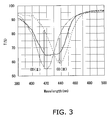
- the porphyrin supported on the NO concentration measurement sensor 30 described above changes in the opposite direction, having light quantity gas isosbestic points at the peak wavelengths (435 nm and 415 nm) of the absorption spectrum, according to the extent of the reaction with NO. For example, when the NO concentration in exhaled air introduced into the chamber 13 rises, the 415 nm light quantity goes up and the 435 nm light quantity goes down. On the other hand, when the NO concentration in the exhaled air introduced into the chamber 13 drops, the 415 nm light quantity goes down and the 435 nm light quantity goes up. In FIG.
- the one-dot chain line is the transmission spectrum curve of a state in which almost all of the cobalt in the detection region is divalent
- the broken line is the transmission spectrum curve of a state in which almost all of the cobalt in the detection region is trivalent
- the solid line is the transmission spectrum curve of a state in which divalent cobalt and trivalent cobalt are both present in substantially the same amounts in the detection region.
- the sensitivity correction processor 19 inputs the outputs from the current/voltage converting circuit 16d on the 415 nm light quantity detector 16 side and from the differential processor 18.
- the memory unit 20, which is used for storing information necessary for NO concentration measurement and correction, is connected to the sensitivity correction processor 19.
- Calibration data for converting the value of the differential output from the differential processor 18 (voltage value) into a NO concentration value, and sensitivity correction information used for correction of the differential output based on the 415 nm light quantity (discussed in detail below) are pre-stored in the memory unit 20.
- the above-mentioned calibration data is data (a mathematical formula or a graph) indicating the relation between a standard substance of known quantity, activity, etc., and the measured data with respect to it, and is used in quantitative experiments and testing to find the quantity or concentration of a substance, activity, or the like. Since there is nothing special about the calibration data used in this embodiment, it will not be described in detail here.
- the sensitivity correction information used for correcting the differential output based on the 415 nm light quantity will be described below.
- the correlation lines shown in FIG. 5 are a graph of the correlation between the amount of change in the differential output at various NO concentrations and the 415 nm light quantity during zero gas correction with respect to a plurality of sensors when NO was introduced into the chamber 13 in concentrations of 10, 100, and 500 ppb following zero gas correction. These correlation lines show that regardless of the NO concentration, when the 415 nm light quantity is smaller, there is a rise in the amount of change in the differential output of the NO concentration measurement sensor 30, and when the 415 nm light quantity is larger, there is a decrease in the amount of change in the differential output of the NO concentration measurement sensor 30.
- saying that the 415 nm light quantity is large means that the amount of 415 nm light that is absorbed is small, and there is a reduction in the amount of change in the differential output because a relatively small amount of porphyrin has reacted with NO.
- saying that the 415 nm light quantity is small means that the amount of 415 nm light that is absorbed is large, and there is an increase in the amount of change in the differential output because a relatively large amount of porphyrin has reacted with NO.
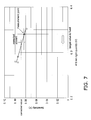
- FIG. 6 is a graph of the relation between the amount of change in the differential output and the slope of the correlation line.
- the amount of change in the differential output on the horizontal axis of the graph in FIG. 6 is strongly correlated with NO concentration since the change increases when the NO concentration is higher and decreases when the NO concentration is lower.
- the sensitivity correction processor 19 that has obtained the differential output from the differential processor 18 can find the value of the slope of the correlation line on the vertical axis by using the above mathematical formula (2) or by plugging the value thereof into the numerical value on the horizontal axis on the basis of the graph in FIG. 6 .
- the NO concentration measurement sensor 30 used in the nitrogen oxide concentration measurement device 10 of this embodiment is a transmission type of sensor that transmits light emitted from the LED light source 11, and the porphyrin shown in FIG. 2 (CoT(dtBu)PP) is supported at the portion where the light is transmitted.
- the NO concentration measurement sensor 30 is manufactured by preparing a solution in which a powder of the porphyrin shown in FIG. 2 (CoT(dtBu)PP) is dissolved in a concentration of 5E-5 mol/L in chloroform (guaranteed reagent) or another such solvent, and dripping this solution in drops of 10 ⁇ L each from a drip nozzle with an inside diameter of 200 ⁇ m onto the base material 31 composed of paper (cellulose) or nonwoven cloth made of PET (polyethylene terephthalate) fibers.
- the base material 31 can be, for example, a nonwoven cloth made from PET fibers, or a nonwoven cloth made from cellulose fibers (such as filter paper grade 514A, made by Advantec).
- the liquid discharge apparatus used for dripping the porphyrin solution onto the base material 31 can be, for example, a Shot Master (with a height control device) made by Musashi Engineering.
- the NO concentration measurement sensor 30 is manufactured under the following conditions for the height of the drip nozzle, the discharge rate of the porphyrin, the discharge amount, and the like, so that the porphyrin will penetrate the base material 31 in an agglomerated state by about the same amount each time. This is because if the agglomerated state of the porphyrin changes every time, the degree of correlation will suffer and the sensitivity variance correction effect will decrease.
- the drip nozzle height was 0 to 5 ⁇ m
- the discharge amount was 10 ⁇ L
- the discharge speed was 20 seconds
- the diameter of the drip nozzle was 200 mm
- the base material was paper (grade 514A).
- FIG. 8 shows the variance in NO sensitivity when the drip nozzle height was varied.
- the horizontal axis shows the 415 nm light quantity and the vertical axis shows the 100 ppb NO sensitivity.
- the NO sensitivity under a 100 ppb NO concentration environment is shown at different drip nozzle heights.
- the drip nozzle heights of -40 ⁇ m, 0 ⁇ m, +50 ⁇ m, and -20 ⁇ m shown in FIG. 8 are distances indicating the height from the surface of the base material 31 to the drip nozzle tip, and negative (-) values refer to a state in which the nozzle tip is recessed under the surface of the base material 31.
- FIG. 9 the nozzle position is shown on the horizontal axis, and the R 2 value representing the degree of correlation is shown on the vertical axis.
- This graph shows the height of correlation between the 415 nm light quantity and the NO sensitivity under an NO concentration environment of 100 ppb.
- the height of the drip nozzle is preferably from -25 to 25 ⁇ m. It was found experimentally that a good sensitivity variance correction effect can be obtained if the R 2 value is 0.9 or more.
- Sensitivity variance due to changes in the agglomeration state of the porphyrin from one NO concentration measurement sensor 30 to the next can be minimized by manufacturing in which the porphyrin solution is dripped under the above conditions. Sensitivity variance can be kept to a minimum by combination with the following correction control.
- the change in the amount of light of a specific wavelength (415 or 435 nm) is detected, out of the transmitted light emitted from the LED light source 11 at the NO concentration measurement sensor 30 in a state in which exhaled air from an asthma patient or the like has been introduced into the chamber 13, inside of which the NO concentration measurement sensor 30 has been installed, and the differential output (NO concentration value) is corrected by utilizing the correlation lines shown in FIG. 5 , using the differential output and the 415 nm light quantity.
- the nitrogen oxide concentration measurement device 10 in this embodiment first the 415 nm light quantity is detected by the 415 nm light quantity detector 16 out of the light transmitted by the portion of the NO concentration measurement sensor 30 where the porphyrin is supported, in a state in which correction-use zero gas has been introduced into the chamber 13, and this detection result is sent as a voltage value to the sensitivity correction processor 19.
- the differential processor 18 subtracts the voltage value indicating the 435 nm light quantity from the voltage value indicating the 415 nm light quantity, calculates the differential (differential output), and outputs this to the sensitivity correction processor 19.
- exhaled air is introduced into the chamber 13, and the 415 nm light quantity and the 435 nm light quantity are detected by the 415 nm light quantity detector 16 and the 435 nm light quantity detector 17, respectively, out of the light transmitted by the portion of the NO concentration measurement sensor 30 where the porphyrin is supported.
- the 415 nm light quantity detector 16 and the 435 nm light quantity detector 17 output their detection results as voltage values to the differential processor 18, and the differential processor 18 subtracts the voltage value indicating the 435 nm light quantity from the voltage value indicating the 415 nm light quantity, calculates the differential (differential output), and outputs this to the sensitivity correction processor 19.
- the sensitivity correction processor 19 calculates the slope of the correlation lines shown in FIG. 5 on the basis of the value of the differential output (voltage value) received from the differential processor 18, and sensitivity correction information stored in the memory unit 20 (in this embodiment, the above mathematical formula (2)). More specifically, the sensitivity correction processor 19 plugs in the value of the differential output as the value of x in the above mathematical formula (2), and calculates the y value (the slope of the correlation lines in FIG. 5 ).
- a mathematical formula may be used as in this embodiment as the correction sensitivity information for calculating the slope of the correlation line, or a table giving the relation between the differential output and the slope of the correlation line, or the graph shown in FIG. 6 can be used.
- the sensitivity correction processor 19 corrects the differential output on the basis of the voltage value indicating the 415 nm light quantity received from the current/voltage converting circuit 16d of the 415 nm light quantity detector 16 with respect to the correction-use zero gas, the preset reference value for the 415 nm light quantity shown in FIG. 7 , and the y value (slope of the correlation line) calculated on the basis of the mathematical formula (2).
- FIG. 7 shows an example of a straight line having a slope of when the NO concentration is 100 ppb, but actually the slope varies with the NO concentration, so we shall assume that the differential output is corrected by utilizing a correlation line having a slope calculated from mathematical formula (2).
- the measurement point is moved with respect to the preset reference value of the 415 nm light quantity along the correlation line, so that the measurement result is corrected as if the amount of absorption were not changing.
- the corrected value is calculated by plugging in 0.328 V, which corresponds approximately to the center of the correlation line shown in FIG. 7 , for the value x in the mathematical formula as a target value, and the corrected value is calculated as the voltage value (approximately 0.881) indicating sensitivity after correction from the voltage value (approximately 0.831) prior to correction, which indicates the sensitivity at the measurement point.
- the sensitivity correction processor 19 converts the corrected voltage value 0.881 into an NO concentration using a calibration data curve, allowing a corrected NO concentration value to be obtained.
- the nitrogen oxide concentration measurement device 110 pertaining to another embodiment of the present invention will now be described through reference to FIGS. 10 to 14 .
- the nitrogen oxide concentration measurement device 110 pertaining to this embodiment is an apparatus for measuring the concentration of nitric oxide (NO) in the exhaled air of asthma patients, etc. As discussed below, in this embodiment the NO concentration is measured in particular on the basis of the amount of transmitted light from an NO concentration measurement sensor 130.
- the NO concentration measurement sensor 130 will be described in detail below.
- the nitrogen oxide concentration measurement device 110 comprises a mouthpiece 111, an NO scrubber 112, a zero scrubber 113, a dryer 114, a chamber 115, valves 116 and 117, a compressor 119, and tubing to link the various units.
- the tubing and the valves 116 and 117 form a first path 181, a second path 182, and a third path 183.
- the first path 181 leads from the compressor 119, through the zero scrubber 113 and the dryer 114, to the chamber 115.
- One end of the second path 182 is connected to the NO scrubber 112, and the other end is connected to the mouthpiece 111 and via the valve 116.
- the third path 183 leads from the mouthpiece 111, without passing through the zero scrubber 113, through the dryer 114, to the chamber 115.
- the nitrogen oxide concentration measurement device 110 may also comprise a flow gauge for measuring the flow or pressure of exhaled air and atmospheric air, a pressure gauge, a thermometer for sensing temperature, and so forth.
- the mouthpiece 111 is formed so that the user can place it against his mouth and blow into it.
- the NO scrubber 112 has a hole for taking in air.
- the NO scrubber 112 is configured so as to eliminate NO from the air by being equipped with activated carbon, potassium permanganate, or the like.
- the zero scrubber 113 is configured so as to eliminate NO from exhaled air blown in from the mouthpiece 111, by being equipped with activated carbon, potassium permanganate, or the like.
- the NO scrubber 112 and the zero scrubber 113 may instead be constituted by a single scrubber.
- the dryer 114 is equipped with silica gel, for example, and is configured so as to dehumidify the exhaled air.
- the chamber 115 is a housing inside of which the NO concentration measuring sensor 130 is installed, and has a gas inlet 115a into which exhaled air or the like is introduced, and a gas outlet 115b for discharging the same.
- the compressor 119 pumps air into the zero scrubber 113.
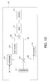
- the nitrogen oxide concentration measurement device 110 further comprises an LED light source 121, a constant current drive circuit 122, a lens 123, a dichroic mirror 124, a 415 nm transmitted light quantity detector 125, a 435 nm transmitted light quantity detector 126, a differential amplifier circuit 127, a controller 128, and a memory unit 129.
- the LED light source 121 emits light under specific conditions onto the NO concentration measurement sensor 130 provided in the chamber 115.
- the constant current drive circuit 122 adjusts the amount of light directed at the NO concentration measurement sensor 130 from the LED light source 121 by varying the current applied to the LED light source 121 under the control of the controller 128.
- the lens 123 and the dichroic mirror 124 are disposed in that order between the chamber 115 and the 415 nm transmitted light quantity detector 125 and 435 nm transmitted light quantity detector 126.
- the dichroic mirror 124 transmits light near 415 nm out of all the light transmitted by the NO concentration measurement sensor 130 and received via the lens 123, and reflects light of other wavelengths.
- the 415 nm transmitted light quantity detector 125 is disposed along the path of the light transmitted by the dichroic mirror 124. As shown in FIG. 10 , the 415 nm transmitted light quantity detector 125 comprises a bandpass filter (BPF) 125a, a lens 125b, a photodiode (PD) 125c, and a current/voltage conversion circuit 125d.
- BPF bandpass filter
- PD photodiode
- the bandpass filter 125a is an optical filter that transmits only light near 415 nm. That is, the bandpass filter 125a separates the 415 nm light from the light transmitted by the dichroic mirror 124 and the NO concentration measurement sensor 130, and guides this light to the lens 125b.
- the lens 125b guides the 415 nm light transmitted by the bandpass filter 125a to the photodiode 125c.
- the photodiode 125c outputs a current corresponding to the amount of light received.
- the current/voltage conversion circuit 125d converts the current coming from the photodiode 125c into voltage and outputs it to the differential amplifier circuit 127 and the controller 128.
- the 415 nm transmitted light quantity detector 125 takes out the 415 nm light from the light transmitted by the NO concentration measurement sensor 130, and detects the amount of this light.
- the 435 nm transmitted light quantity detector 126 is disposed along the path of light transmitted by the NO concentration measurement sensor 130 and reflected by the dichroic mirror 124. As shown in FIG. 10 , the 435 nm transmitted light quantity detector 126 comprises a bandpass filter 126a, a lens 126b, a photodiode 126c, and a current/voltage conversion circuit 126d.
- the bandpass filter 126a transmits only light near 435 nm.
- the lens 126b guides the light transmitted by the bandpass filter 126a to the photodiode 126c.
- the photodiode 126c outputs a current corresponding to the amount of light received.
- the current/voltage conversion circuit 126d converts the current coming from the photodiode 126c into voltage and outputs it to the differential amplifier circuit 127.
- the 435 nm transmitted light quantity detector 126 takes out the 435 nm light from the light transmitted by the NO concentration measurement sensor 130, and detects the amount of this light.
- the differential amplifier circuit 127 outputs to the controller 128 the difference D (Vi - Vii) between the voltage value outputted from the 415 nm transmitted light quantity detector 125 (that is, the signal Vi) and the voltage value outputted from the 435 nm transmitted light quantity detector 126 (that is, the signal Vii).
- the controller 128 controls the operation of the various units of the nitrogen oxide concentration measurement device 110, and also performs concentration calculation and the like.
- data such as calibration curve selection-use tables, calibration curves, and so forth is stored in the memory unit 129.
- the operation of the nitrogen oxide concentration measurement device 110 will be discussed below.
- the NO concentration measurement sensor 130 comprises a base material and a metal complex of porphyrin or a derivative thereof (hereinafter also referred to simply as "metal complex") that is supported on the base material.
- the base material may be any material that allows light to pass through, including a reflective material such as alumina, or a woven cloth, nonwoven cloth, porous material, or the like made of glass fibers or polyester, polypropylene, cellulose, or another such polymer.
- Nonwoven cloth is a structure made up of fibers that are intertwined without being woven, and paper is also encompassed by the concept of nonwoven cloth in this Specification.
- An example of a polyester is PET (polyethylene terephthalate).
- the metal complex is preferably worked into the base material.
- the base material may be seeped with the metal complex, or an NO concentration measurement sensor may be formed by a mixture of a base material and a metal complex.
- the metal complex is one whose transmission spectrum (also called the absorption spectrum) changes when exposed to a nitrogen oxide.
- Derivatives of porphyrin encompass substances in which a substituent has been bonded to a porphyrin skeleton.
- substituents include a hydrocarbon group such as alkyl group, an alkylene group, or an aryl group, which may be branched; an alkoxy group such as a methoxy group or an ethoxy group; a halogen group; a hydroxy group; an amino group; an imino group; a nitro group, and a carbonyl group.
- Examples of the metal that forms a coordinate bond with the porphyrin include cobalt, iron, magnesium, nickel, zinc, and vanadium.
- the NO concentration measurement sensor 130 comprises a nonwoven cloth and a metal complex supported on the nonwoven cloth (that is, that impregnates the nonwoven cloth).
- the NO concentration measurement sensor 130 also comprises as a metal complex the CoT(dtBu)PP shown in FIG. 2 , that is, a cobalt complex of a porphyrin derivative having a tertiary butyl group (t-Bu) located at the 3,5-position of a phenyl group.
- a metal complex the CoT(dtBu)PP shown in FIG. 2 , that is, a cobalt complex of a porphyrin derivative having a tertiary butyl group (t-Bu) located at the 3,5-position of a phenyl group.
- the CoT(dtBu)PP has an absorption peak near 415 to 420 nm the valence of the cobalt is 2 (Co(II)).
- the valence of cobalt changes from divalent to trivalent (Co(III)) when exposed to NO.
- Co(III) has an absorption peak near 435 to 440 nm.
- the NO concentration can be measured by comparing the amount of light of a specific wavelength transmitted from the NO concentration measurement sensor 130 prior to exposure to the detected gas, and the amount of light of the specific wavelength transmitted from the NO concentration measurement sensors 130 after exposure.
- the differences D1 and D2 between a signal corresponding to the 415 nm light quantity and a signal corresponding to the 435 nm light quantity are acquired before and after exposure of the NO concentration measurement sensor 130 to the detected gas.
- the NO concentration is found on the basis of the difference between these differences D1 and D2 (D2 - D1) and a calibration curve.
- the wavelength of light used for detection can be varied according to the configuration (the types of substituents) and the metal elements of the porphyrin or a derivative thereof. That is, 415 nm is an example of a first wavelength, and 435 nm is an example of a second wavelength.
- the nitrogen oxide concentration measurement device 110 in this embodiment initializes the NO concentration measurement sensor 130 to a cobalt(II) state before the measurement of nitrogen oxide concentration. That is, this initialization puts the NO concentration measurement sensor 130 in a state of not being exposed to the substance to be detected.
- the central metal of the complex is cobalt, and as discussed above, the NO concentration is measured on the basis of a change in the valence of the cobalt from divalent to trivalent.
- cobalt will change from Co(II) to Co(III) when the NO concentration measurement sensor 130 reacts with O 2 , nitrogen oxides, or the like in the atmosphere. Such changes reduce the detection accuracy. Therefore, the cobalt is reduced to Co(II) by initialization before being exposed to the detected gas.
- Initialization is carried out by applying heat or light to the NO concentration measurement sensor 130.
- Uptake of the exhaled air of the user is as follows. Switching of the path by the valves 116 to 118 is performed under the control of the controller 128.
- the first path 181 is opened up by the valves 116 and 117. That is, the compressor 119, the zero scrubber 113, and dryer 114 are connected. NO is removed by the zero scrubber 113 from the air pumped in by the compressor 119, dehumidified by the dryer 114, and then goes into the chamber 115. The NO concentration measurement sensor 130 is thus exposed to air from which NO has been removed.
- the third path 183 is opened up by the valves 116 and 117.
- the exhaled air enters the chamber 115 via the dryer 114 and the mouthpiece 111.
- the exhaled air at this point does not pass through the zero scrubber 113, so NO is included in the exhaled air.
- exhaled air Air from which NO has been removed will hereinafter be referred to as "zero gas,” while exhaled air blown through the mouthpiece 111 will be referred to simply as “exhaled air.”
- the exhaled air corresponds to the gas to be measured, and zero gas is a calibration gas for calibrating to 0 ppb.
- the third path 183 leading from the mouthpiece 111 to the chamber 115 without passing through the zero scrubber 113 is a measured gas exposure path along which the NO concentration measurement sensor 130 is exposed to the measured gas
- the first path 181 leading from the compressor 119 to the chamber 115 through the zero scrubber 113 is a zero gas exposure path along which the NO concentration measurement sensor 130 is exposed to zero gas.
- initialization is performed in a state in which the NO concentration measurement sensor 130 is disposed in the chamber 115 (step S1).
- step S2 zero gas is introduced into the chamber 115 (step S2).
- an initial signal V0 is acquired (step S3). More specifically, this entails the following. First, current is applied from the constant current drive circuit 122 to the LED light source 121, which causes the NO concentration measurement sensor 130 that is being exposed to the zero gas to be irradiated with light.
- the light transmitted by the NO concentration measurement sensor 130 goes through the lens 123 and is incident on the dichroic mirror 124.
- the incident light is separated by the 124 dichroic mirror into light near 415 nm and other light.
- the transmitted by the dichroic mirror 124 (that is, light near 415 nm) is incident on the 415 nm transmitted light quantity detector 125, and of this, the 415 nm is transmitted by the bandpass filter 125a and guided through the lens 125b to the photodiode 125c.
- the current value outputted by the photodiode 125c according to the amount of light received is converted into a voltage value by the current/voltage conversion circuit 125d and outputted to the controller 128.
- the voltage signal thus generated is called the initial signal V0.
- the initial signal V0 corresponds to the 415 nm light quantity transmitted by the NO concentration measurement sensor 130 during zero gas exposure.
- the controller 128 selects one calibration curve to be used in conversion to concentration (that is, in calibration) from among the calibration curves I to III ( FIG. 13 ) stored in the memory unit 129 on the basis of the initial signal (step S4).
- the calibration curves I to III are an example a plurality of sets of calibration information.
- the calibration curves I to III each have a different correlation to the NO concentration and the concentration signal. That is, in at least in part of the calibration curve I, the NO concentration corresponding to a given concentration signal is different from the NO concentration corresponding to that concentration signal in calibration curve II or III. The same applies to calibration curves II and III.
- the calibration information is not limited to three sets, and the number of sets may be changed. Calibration curves I to III can be found experimentally.
- the memory unit 129 also stores at least one threshold used for calibration curve selection.
- the memory unit 129 stores two threshold values, namely, 0.11 and 0.13. More specifically, the memory unit 129 stores the following calibration curve selection table.
- Table 1 Calibration curve Initial signal (V) I less than 0.11 II at least 0.11 and less than 0.13 III at least 0.13
- calibration curve I is selected if the initial signal is less than 0.11 V
- calibration curve II is selected if the initial signal is at least 0.11 V but less than 0.13
- calibration curve III is selected if the initial signal is at least 0.13 (step S4).
- the initial signal V0 generated as above is outputted as a signal V i 1 to the differential amplifier circuit 127.
- the light reflected by the dichroic mirror 124 (that is, transmitted light that is not near 415 nm) is incident on the bandpass filter 126a of the 435 nm transmitted light quantity detector 126.
- the 435 nm light transmitted by the bandpass filter 126a is guided through the lens 126b to the photodiode 126c.
- the current value outputted by the photodiode 126c according to the amount of light received is converted by the current/voltage conversion circuit 126d into a voltage value (that is, a signal V ii 1).
- the Signal V ii 1 is outputted to the differential amplifier circuit 127.
- exhaled air that is, the measured gas
- exhaled air that is, the measured gas
- the absorption spectrum of the metal complex contained by the NO concentration measurement sensor 130 fluctuates with the amount of NO in the exhaled air, with the 415 nm light quantity transmitted by the NO concentration measurement sensor 130 increasing, and the 435 nm light quantity transmitted by the NO concentration measurement sensor 130 decreasing.
- the amount of change in the 415 nm light quantity and the 435 nm light quantity transmitted by the NO concentration measurement sensor 130 is a function of the amount of change in the NO concentration from the zero gas to the measured gas.
- a second difference D2 (V i 2 - V ii 2) is acquired (step S7). More specifically, the signal V i 2, which is the voltage corresponding to the 415 nm light quantity transmitted by the NO concentration measurement sensor 130 with respect to the NO concentration measurement sensor 130 exposed to exhaled air, is acquired by the 415 nm transmitted light quantity detector 125, while the signal V ii 2, which is the voltage corresponding to the 435 nm light quantity transmitted by the NO concentration measurement sensor 130, is acquired by 435 nm transmitted light quantity detector 126.
- the differential amplifier circuit 127 outputs the second difference D2 (V i 2 - V ii 2) to the controller 128.
- the controller 128 acquires a concentration signal C by acquiring the difference (D2 - D1) between the first difference D1 and the second difference D2 (step S8).
- the controller 128 finds the NO concentration (ppb) corresponding to the concentration signal C thus obtained, from the calibration curve selected in step S4 (step S9).
- the controller 128 functions as a calibration information selector and a concentration determination unit.
- Variance in the amount of metal complex and so forth between individual NO concentration measurement sensors 130 causes variance in sensitivity to NO (the amount of change in the amount of transmitted light with respect to the amount of change in the NO concentration). This variance appears in the variance in the initial signal.
- measurement error caused by variance in the sensitivity of the NO concentration measurement sensor 130 can be suppressed by selecting a calibration curve based on the initial signal.
- the NO concentration measurement sensor 130 comprises a base material into which the metal complex seeps, such as woven cloth, nonwoven cloth, or a porous material, variance in sensitivity tends to occur even though manufacture is performed under the same conditions. As a result, even though the exhaled air contains NO in the same concentration, there is the risk that different concentration values will be outputted as the measurement result due to sensitivity variance between NO concentration measurement sensors.
- Variance in the sensitivity of an NO concentration measurement sensor such as this correlates with the amount of light transmitted by the NO concentration measurement sensor prior to exposure to NO. Specifically, the smaller is the amount of light transmitted prior to exposure to NO (that is, the lower is the initial signal strength), the higher is the sensitivity (that is, the greater is the amount of change in the amount of transmitted light at a given NO concentration). The larger is the amount of light transmitted prior to exposure to NO, the lower is the sensitivity (that is, the smaller is the amount of change in the amount of transmitted light at a give NO concentration).
- the nitrogen oxide concentration measurement device 110 in this embodiment can suppress variance in the measurement result by selecting a different calibration curve according to the initial signal strength.
- FIG. 4 shows some of the steps of manufacturing the NO concentration measurement sensor 130 in this experimental example.
- Grade 514A filter paper made by Advantec nonwoven cloth of cellulose fibers, was cut with scissors to a size of 10 x 15 mm, dried at 130°C for 1.5 hours, and used as the base material 31.
- a CoT(dtBu)PP powder was dissolved in chloroform (guaranteed reagent) to obtain a metal complex solution with a concentration of 5E-5 mol/L.
- the metal complex solution was dripped onto the base material 31 at a discharge amount of 10 ⁇ L, a discharge rate of 20 seconds, and a drip nozzle diameter of 200 mm.
- An NO concentration measurement sensor was produced by varying the drip nozzle height (the height from the surface of the base material 31 to the drip nozzle) in order to optimize the height of the drip nozzle.
- the sensitivity of the various NO concentration measurement sensors was compared for a gas with a known NO concentration, whereupon the inventors discovered that a drip nozzle height of from -25 ⁇ m to 25 ⁇ m is preferable to suppress variance in the sensitivity of an NO concentration measurement sensor.
- gas cylinder 001 compressed air gas cylinder 002: 2.038 ppm NO base gas N 2
- gas cylinder 003 0.206 ppm NO base gas N 2
- Each of the NO concentration measurement sensors manufactured as above was put in the chamber, and initialization with light was performed while compressed air was pumped from the gas cylinder 001 into the chamber at a flow rate of 100 mL per minute.
- (+)NO gas is a gas containing NO, and in this experimental example it is the measured gas used as simulated exhaled air.
- the mix ratio of the compressed air and NO was varied, the NO concentration was adjusted to 100, 300, 500, 700, and 1000 ppb at a total flow rate of 3L/min, and each gas was pumped into the chamber as the (+)NO gas.
- the mix ratio of the compressed air and NO was similarly varied using the gas cylinders 003 and 001, and (+)NO gas having an NO concentration of 70, 10, 30, or 50 ppb was prepared and fed into the chamber so that the total flow rate would be 3L/min.
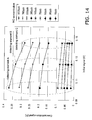
- FIG. 14 is a graph showing the relation between the initial signal and the concentration signal obtained with each NO concentration measurement sensor. As shown in FIG. 14 , it was found that the slope increases as the actual NO concentration rises. That is, it was found that accurate concentration measurement is difficult with a single calibration curve.
- the NO concentration was calculated on the basis of the calibration curve selection table, using the concentration signal of the NO concentration measurement sensor A as calibration curve I, the concentration signal of the NO concentration measurement sensor B as calibration curve II, and the concentration signal of the NO concentration measurement sensor C as calibration curve III.
- the nitrogen oxide concentration measuring device 210 pertaining to yet another embodiment of the present invention will now be described through reference to FIGS. 15 to 19 .
- the output value from the current/voltage conversion circuit 216d shown in FIG. 15 refers to a voltage value (V) corresponding to the amount of light detected with a wavelength of 415 nm
- the amount of change in the output value from a differential processor 218 with respect to a specific amount of change in NO concentration refers to a voltage value (V) corresponding to sensitivity
- the nitrogen oxide concentration measuring device 210 pertaining to this embodiment is a device that introduces exhaled air into a chamber 213 in which a nitric oxide (NO) (nitrogen oxide) concentration measurement sensor 230 is installed, detects the amount of light of a peak wavelength of the absorption spectrum that varies with the degree of reaction between NO and porphyrin (CoT(dtBu)PP) supported on the NO concentration measurement sensor 230 (see FIG. 2 ), and measures the concentration in which NO is contained in the exhaled air an asthma patient or the like.
- NO nitric oxide
- COT(dtBu)PP porphyrin
- the nitrogen oxide concentration measuring device 210 comprises an LED light source 211, a constant current drive circuit 212, the chamber 213, a lens 214, a dichroic mirror 215, a 415 nm light quantity detector (light detector, first detector) 216, a 435 nm light quantity detector (light detector, second detector) 217, a differential processor 218, a controller 219, and a memory unit 220.
- the LED light source 211 irradiates the NO concentration measurement sensor 230 provided inside the chamber 213 with light under specific conditions.
- the constant current drive circuit 212 is a circuit for determining the current applied to the LED light source 211, and adjusts the amount of light emitted from the LED light source 211 (hereinafter referred to as LED light quantity) by varying the current value to be applied.
- the constant current drive circuit 212 is connected to the controller 219, and the measurement current is adjusted by feedback control of the amount of light detected with a wavelength of 415 nm (discussed below).
- the constant current drive circuit 212 applies initialization current of 200 mA to the LED light source 211 during initialization of the NO concentration measurement sensor 230, and applies a measurement current of 25 mA upon initial application in the measurement of NO concentration.
- initialization refers to a process at the stage of manufacturing the NO concentration measurement sensor 230, in which a porphyrin solution is dripped onto a base material 31 (see FIG. 4 ), after which the oxygen coordinate bonded to trivalent cobalt, which is the central metal of the porphyrin, is reduced to divalent.
- the NO concentration measurement sensor 230 on which porphyrin is supported will be described in detail at a later stage.
- the chamber 213 is a housing inside of which the NO concentration measuring sensor 230 is installed, and has a gas inlet 213a into which exhaled air or the like is introduced, and a gas outlet 213b for discharging the same.
- the light that has been emitted from the LED light source 211 and transmitted from the NO concentration measurement sensor 230 installed in the chamber 213 is guided by the lens 214 to the dichroic mirror 215, which is disposed at a later stage.
- the dichroic mirror 215 transmits light near a specific wavelength (415 nm in this embodiment) out of the light transmitted by the NO concentration measurement sensor 230 and received via the lens 214, and reflects light of other wavelengths. This allows just the light of a specific wavelength (415 nm) to be taken out of the transmitted light.
- the 415 nm light quantity detector 216 takes out light with a wavelength of 415 nm from the light transmitted by the dichroic mirror 215, and detects the amount of this light (hereinafter referred to as the 415 nm light quantity). As shown in FIG. 15 , the 415 nm light quantity detector 216 has a bandpass filter (BPF) 216a, a lens 216b, a photodiode (PD) 216c, and the current/voltage converting circuit 216d.
- BPF bandpass filter
- PD photodiode
- the bandpass filter 216a transmits light with a wavelength near 415 nm out of the light transmitted by the dichroic mirror 215.
- the lens 216b guides the light near 415 nm transmitted by the bandpass filter 216a to the photodiode 216c disposed at a later stage.
- the photodiode 216c converts the light near 415 nm coming from the lens 216b into a current signal and outputs this signal.
- the current/voltage converting circuit 216d converts the electrical signal coming from the photodiode 216c from a current value into a voltage value, and outputs the result to differential processor 218 and the controller 219.
- the 435 nm light quantity detector 217 takes out the light with a wavelength near 435 nm reflected at the dichroic mirror 215, and detects the amount of this light (hereinafter referred to as the 435 nm light quantity). As shown in FIG. 15 , the 435 nm light quantity detector 217 has a bandpass filter (BPF) 217a, a lens 217b, a photodiode (PD) 217c, and a current/voltage converting circuit 217d.
- BPF bandpass filter
- PD photodiode
- the bandpass filter 217a transmits the light with a wavelength near 415 nm reflected at the dichroic mirror 215.
- the lens 217b guides the light near 415 nm transmitted by the bandpass filter 217a to the photodiode 217c disposed at a later stage.
- the photodiode 217c converts the light near 415 nm coming from the lens 217b into a current signal and outputs this signal.
- the current/voltage converting circuit 217d converts the electrical signal coming from the photodiode 217c from a current value into a voltage value, and outputs the result to the differential processor 218 and the controller 219.
- the differential processor 218 outputs the difference between the 415 nm light quantity and the 435 nm light quantity that were converted into voltage values at the current/voltage converting circuit 216d on the 415 nm light quantity detector 216 side and the current/voltage converting circuit 217d on the 435 nm light quantity detector 217 side.
- the controller 219 inputs the outputs from the current/voltage converting circuit 216d on the 415 nm light quantity detector 216 side and from the differential processor 218.
- the controller 219 is connected to the memory unit 220, which stores information required for NO concentration measurement (such as mathematical formulas and calibration curves).
- the controller 219 is also connected to the constant current drive circuit 212, which adjusts the LED light quantity of the LED light source 211, and performs feedback control based on the 415 nm light quantity (discussed below).
- the memory unit 220 stores mathematical formulas (or calibration curves) used for converting the value (voltage value) of the differential output from the differential processor 218 into an NO concentration value. Consequently, a voltage value can be converted into a concentration value, and the NO concentration value can be calculated, by plugging the differential output of the 415 nm light quantity and the 435 nm light quantity into a mathematical formula or the like stored in the memory unit 220.
- the above-mentioned calibration curve is a graph of the relation between a standard substance of known quantity, activity, etc., and the measured data with respect to it, and is used in quantitative experiments and testing to find the quantity or concentration of a substance, activity, or the like.
- the calibration curve used in this embodiment is a graph produced by acquiring the same data using a plurality of NO concentration measurement sensors 230 at the point when conditions have been determined, and using the average value thereof (see FIG. 1 , for example).
- This calibration curve will appear as different graphs depending on the base material and porphyrin concentrations, the conditions for dripping the porphyrin solution, and other conditions.
- FIG. 19 is merely an example of this.
- the NO concentration measurement sensor 230 used in the nitrogen oxide concentration measurement device 210 of this embodiment is a transmission type of sensor that transmits light emitted from the LED light source 211, and the porphyrin shown in FIG. 2 (CoT(dtBu)PP) is supported at the portion where the light is transmitted.
- the NO concentration measurement sensor 230 is manufactured by preparing a solution in which a powder of the porphyrin shown in FIG. 2 (CoT(dtBu)PP) is dissolved in a concentration of 5E-5 mol/L in chloroform (guaranteed reagent) or another such solvent, and dripping this solution in drops of 0.5 to 30 ⁇ L each from a drip nozzle with an inside diameter of from 50 ⁇ m to 1 mm onto a base material 31 composed of paper (cellulose) or nonwoven cloth made of PET (polyethylene terephthalate) fibers.
- the concentration of the porphyrin solution is determined by the amount of light absorption, which varies with the material, thickness, basis weight, and so forth of the sensor base material, and is the concentration at which the amount of absorption of 415 or 435 nm light will be from 30 to 80%.
- the production cost will go up if the nozzle diameter is less than 50 ⁇ m (inside diameter), and depending on the drip time and drip quantity, the internal pressure may rise, resulting in liquid leakage. If the diameter is over 1 mm, there is the risk of unwanted dripping or a change in concentration due to drying of the solvent.
- the base material 31 can be, for example, a nonwoven cloth made from PET fibers, or a nonwoven cloth made from cellulose fibers (such as filter paper grade 514A, made by Advantec).
- the liquid discharge apparatus used for dripping the porphyrin solution onto the base material 31 can be, for example, a Shot Master (with a height control device) made by Musashi Engineering.
- the NO concentration measurement sensor 230 is manufactured under the following conditions for the height of the drip nozzle, the discharge rate of the porphyrin, the discharge amount, and the like, so that the porphyrin will penetrate the base material 31 uniformly.
- the drip nozzle height was 5 ⁇ m
- the discharge amount was 10 ⁇ L
- the discharge speed was 20 seconds
- the diameter of the drip nozzle was 200 mm
- the base material was paper (filter paper grade 514A, made by Advantec).
- FIG. 8 shows the variance in NO sensitivity when the drip nozzle height was varied.
- the horizontal axis shows the 415 nm light quantity and the vertical axis shows the 100 ppb NO sensitivity.
- the NO sensitivity under a 100 ppb NO concentration environment is shown at different drip nozzle heights.
- the drip nozzle heights of -40 ⁇ m, 0 ⁇ m, +50 ⁇ m, and -20 ⁇ m shown in FIG. 8 are distances indicating the height from the surface of the base material 31 to the drip nozzle tip, and negative (-) values refer to a state in which the nozzle tip is recessed under the surface of the base material 31.
- FIG. 9 the nozzle position is shown on the horizontal axis, and the R 2 value representing the degree of variance is shown on the vertical axis.
- This graph shows the correlation between the 415 nm light quantity and the NO sensitivity under an NO concentration environment of 100 ppb.
- the height of the drip nozzle is preferably from -25 to 25 ⁇ m.
- Sensitivity variance from one NO concentration measurement sensor 230 to the next can be minimized by manufacturing in which the porphyrin solution is dripped under the above conditions. Sensitivity variance can be kept to a minimum by combination with the following correction control.
- the amount of light of a specific wavelength (415 or 435 nm) is detected, out of the transmitted light emitted from the LED light source 211 at the NO concentration measurement sensor 230 in a state in which exhaled air from an asthma patient or the like has been introduced into the chamber 13, inside of which the NO concentration measurement sensor 230 has been installed, and the NO concentration value calculated using the voltage value of the differential output thereof, and mathematical formulas and calibration curves stored in the memory unit 220.
- the controller 219 performs feedback control to adjust the LED light quantity emitted from the LED light source 211 so that the 415 nm light quantity (voltage value) at the introduction of the initial NO concentration gas outputted from the 415 nm light quantity detector 216 will be constant.
- the NO detection sensitivity prior to feedback control for each NO concentration measurement sensor 230 can be seen from the experimental results to have a large amount of variance, regardless of the NO concentration, as shown in FIG. 16 . More specifically, at an NO concentration of 100 ppb, for example, it can be seen that the 415 nm light quantity varies over a range of 0.023 to 0.036 V for NO detection sensitivity from approximately 1.4 V to approximately 2.3 V.
- FIG. 16 shows a graph of correlation lines indicating the relation between the NO detection sensitivity and the 415 nm light quantity when the NO concentration was 20 and 200 ppb. As shown in FIG. 16 , it can be seen that when the NO concentration changes, the slope of the correlation line also changes.
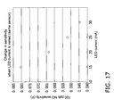
- the NO detection sensitivity changes along with an increase or decrease in the LED current applied to the LED light source 211 (the LED light quantity emitted from the LED light source 211). More specifically, as shown in FIG. 17 , when the value of the LED current is increased to 25 and 30 mA, the NO detection sensitivity decreases to 0.052 and 0.044 V. Conversely, when the value of the LED current is decreased to 20 and 15 mA, the NO detection sensitivity rises to 0.064 and 0.081 V.
- the relation between NO detection sensitivity and LED current value has the correlation shown in FIG. 17 . That is, it can be seen from the experimental results in FIG. 17 that by adjusting the LED current value, it is possible to control the amount of light emitted from the LED light source 211, and NO detection sensitivity can be controlled to some extent.
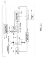
- the LED light quantity emitted from the LED light source 211 via the constant current drive circuit 212 is subjected to feedback control so that the 415 nm light quantity will remain constant during introduction of the initial NO concentration gas detected at the 415 nm light quantity detector 216.
- the nitrogen oxide concentration measuring device 210 using the configuration shown in FIG. 20 , first the 415 nm light quantity is detected with the 415 nm light quantity detector 216 out of the light transmitted through the portion of the NO concentration measurement sensor 230 where the porphyrin is supported, in a state in which air with an NO concentration of 0 ppb is introduced into the chamber 213.
- the 415 nm light quantity detector 216 outputs this detection result to the controller 219.
- the controller 219 performs feedback control over the LED light quantity emitted from the LED light source 211 so that the voltage value indicating the detected 415 nm light quantity will be a preset target value. More specifically, the current applied from the constant current drive circuit 212 to the LED light source 211 is controlled so that the 415 nm light quantity (voltage value) during introduction of gas with an NO concentration of 0 ppb will be a specific, preset target value (such as 1.0 V).
- This feedback control may be such that a specific value serving as a target value (such as 1.0 V) is reached in a single feedback, or such that the feedback control is split up into a plurality of times and the target value is gradually approached.
- a target value such as 1.0 V
- the controller 219 controls the constant current drive circuit 212 so that the corrected LED current for substantially matching the 415 nm light quantity to the target value is applied to the LED light source 211.
- the differential output at the 415 nm light quantity detector 216 during introduction of a gas with an NO concentration of 0 ppb and during the introduction of exhaled air is converted into an NO concentration value (ppb).
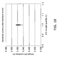
- the NO concentration value thus obtained is a measurement result in a state in which variance in the NO detection sensitivity shown in FIG. 18 has been suppressed by the above-mentioned feedback control, this value can be acquired as a very accurate, corrected NO concentration.
- feedback control is performed on the LED light quantity on the basis of the 415 nm light quantity, which makes it possible to reduce variance in detection sensitivity for each NO concentration measurement sensor 230 that is caused by variance in the amount of porphyrin impregnation, etc., attributable to variance in the thickness of the base material 231 in the NO concentration measurement sensor 230, for example. That is, performing the above-mentioned correction control allows a specific measurement of the amount of porphyrin absorption in the NO concentration measurement sensor 230, etc., to be carried out equivalently.
- very accurate NO concentration measurement can be performed by correcting for measurement error caused by variance in the amount of porphyrin absorption from one NO concentration measurement sensor 230 to the next, the temperature characteristics of the LED light source 211, aging, and so forth.
- the NO sensitivity may be calculated by detecting the amount of light with a wavelength of 435 nm, which reacts in opposite phase to that of the 415 nm wavelength.
- the 415 nm light quantity is detected with the 415 nm light quantity detector 216 out of the light transmitted through the portion of the NO concentration measurement sensor 230 where the porphyrin is supported, in a state in which air with an NO concentration of 0 ppb is introduced into the chamber 213.
- the 415 nm light quantity detector 216 outputs this detection result to the controller 219.
- the controller 219 performs feedback control over the LED light quantity emitted from the LED light source 211 so that the voltage value indicating the detected 415 nm light quantity will be a preset target value. More specifically, the current applied from the constant current drive circuit 212 to the LED light source 211 is controlled so that the 415 nm light quantity (voltage value) during introduction of gas with an NO concentration of 0 ppb will be a specific, preset target value (such as 1.0 V).
- This feedback control may be such that a specific value serving as a target value (such as 1.0 V) is reached in a single feedback, or such that the feedback control is split up into a plurality of times and the target value is gradually approached.
- a target value such as 1.0 V
- the controller 219 controls the constant current drive circuit 212 so that the corrected LED current for substantially matching the 415 nm light quantity to the target value is applied to the LED light source 211.
- the detected output is converted into an NO concentration value (ppb) using a mathematical formula corresponding to a calibration curve pre-stored in the memory unit 220.
- the amount of light of a specific wavelength (415 nm) is detected, feedback control is performed, the LED light quantity emitted from the LED light source 211 is controlled so as always to be constant, and in this state the NO sensitivity is calculated on the basis of the output difference in the amount of light of another wavelength (435 nm) before and after the introduction of exhaled air (NO exposure).
- very accurate NO concentration measurement can be performed by correcting for measurement error caused by variance in the amount of porphyrin absorption from one NO concentration measurement sensor 230 to the next, the temperature characteristics of the LED light source 211, aging, and so forth.
- the NO sensitivity may be calculated on the basis of the output difference in the amount of light with a wavelength of 415 nm before and after the introduction of exhaled air (NO exposure) in a state in which the amount of light when the NO concentration is 0 ppb and the wavelength is 435 nm, and the LED light quantity emitted from the LED light source 211 is always kept constant.
- the 415 nm light quantity is detected with the 415 nm light quantity detector 216 out of the light transmitted through the portion of the NO concentration measurement sensor 230 where the porphyrin is supported, in a state in which air with an NO concentration of 0 ppb is introduced into the chamber 213.
- the 415 nm light quantity detector 216 outputs this detection result to the controller 219.
- the controller 219 performs feedback control over the LED light quantity emitted from the LED light source 211 so that the voltage value indicating the detected 415 nm light quantity will be a preset target value. More specifically, the current applied from the constant current drive circuit 212 to the LED light source 211 is controlled so that the 415 nm light quantity (voltage value) during introduction of gas with an NO concentration of 0 ppb will be a specific, preset target value (such as 1.0 V).
- This feedback control may be such that a specific value serving as a target value (such as 1.0 V) is reached in a single feedback, or such that the feedback control is split up into a plurality of times and the target value is gradually approached.
- a target value such as 1.0 V
- the controller 219 controls the constant current drive circuit 212 so that the corrected LED current for substantially matching the 415 nm light quantity to the target value is applied to the LED light source 211.
- the sum of the absolute values for the amount of change in the detected 415 nm light quantity and the 435 nm light quantity, or the differential output, is converted into an NO concentration value (ppb) using a mathematical formula corresponding to a calibration curve pre-stored in the memory unit 220.
- the NO sensitivity is calculated on the basis of the output difference in the amount of light of two wavelengths (415 and 435 nm) before and after the introduction of exhaled air (NO exposure), in a state in which the amount of light of a specific wavelength (415 nm) is detected, feedback control is performed, and the LED light quantity emitted from the LED light source 211 is always kept constant.
- very accurate NO concentration measurement can be performed by correcting for measurement error caused by variance in the amount of porphyrin absorption from one NO concentration measurement sensor 230 to the next, the temperature characteristics of the LED light source 211, aging, and so forth.
- the NO sensitivity may be calculated on the basis of the output difference in the amount of light with a wavelength of 435 nm and the amount of light with a wavelength of 415 nm before and after the introduction of exhaled air, rather than the output difference in the amount of light with a wavelength of 415 nm and the amount of light with a wavelength of 435 nm before and after the introduction of exhaled air.
- the NO sensitivity is calculated on the basis of the sum of the absolute values of the output difference (differential output) in the amount of light with a wavelength of 415 nm and the amount of light with a wavelength of 435 nm before and after the introduction of exhaled air (NO exposure), while feedback control is performed on the LED light quantity of the LED light source 211, so that the amount of light with a wavelength of 415 nm outputted from the current/voltage conversion circuit 216d will always be constant.
- the NO sensitivity may be calculated on the basis of the sum of the absolute values of the output difference (differential output) in the amount of light with a wavelength of 415 nm and the amount of light with a wavelength of 435 nm before and after the introduction of exhaled air (NO exposure), while feedback control is performed on the LED light quantity of the LED light source 211, so that the amount of light with a wavelength of 435 nm outputted from the current/voltage conversion circuit 217d of the 435 nm light quantity detector 217 will always be constant.
- FIG. 23 is a graph of sensor sensitivity resulting from exposure to 250 ppb of NO 2 .
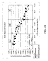
- the horizontal axis (415 nm light quantity) in the graph is divided into a plurality of zones and slope correction is performed in each of these zones, as an application example of the slope correction of a correlation line described in Embodiment 1 above.
- the graph in FIG. 25a corresponds to the A zone in the graph of FIG. 24
- the graph in FIG. 25b to the B zone in the graph of FIG. 24
- the graph in FIG. 25c to the C zone in the graph of FIG. 24 .
- the CV value of the sensitivity variance in each zone was 2.15% in the A zone, 3.12% in the B Zone, and 2.96% in the C Zone. That is, when slope correction was performed on the measurement results included in the graph divided into three zone along the horizontal axis, it was found that accuracy of sensitivity correction could be markedly improved to CV values of 2.15 to 3.12%, compared to the original (undivided) data for slope correction (CV value of 5.42%).
- the out of 415 nm during zero gas exposure (such as the horizontal axis shown in FIG. 24 ) was divided into three zones (A, B, and C), feedback control was applied to the measurement result in each zone so that the amount of light with a wavelength of 415 nm would be 0.16 V in the A zone, 0.185 V in the B zone, and 0.21 V in the C zone, and the 100 ppb NO sensitivity was measured again.
- the CV values in the various zones was 2.19% in the A zone, 2.51% in the B zone, and 1.86% in the C zone. That is, it was found that accuracy of sensitivity correction could be markedly improved to CV values of 1.86 to 2.19%, compared to the original (undivided) data for slope correction (CV value of 5.42%).
- the effect of the nitrogen oxide concentration measurement device of the present invention is that detection error caused by changes in the amount of light due to aging, the temperature characteristics of the light source, or variance in sensitivity from one sensor to the next can be suppressed, and nitrogen oxide concentrations can be measured more accurately, which means that the present invention can be widely applied to sensors that measure the concentration of nitrogen oxides.
Landscapes
- Chemical & Material Sciences (AREA)
- Physics & Mathematics (AREA)
- Health & Medical Sciences (AREA)
- Life Sciences & Earth Sciences (AREA)
- Engineering & Computer Science (AREA)
- General Physics & Mathematics (AREA)
- Pathology (AREA)
- Analytical Chemistry (AREA)
- Biochemistry (AREA)
- General Health & Medical Sciences (AREA)
- Immunology (AREA)
- Chemical Kinetics & Catalysis (AREA)
- Plasma & Fusion (AREA)
- Mathematical Physics (AREA)
- Theoretical Computer Science (AREA)
- Spectroscopy & Molecular Physics (AREA)
- Combustion & Propulsion (AREA)
- Food Science & Technology (AREA)
- Medicinal Chemistry (AREA)
- Investigating Or Analysing Materials By Optical Means (AREA)
- Investigating Or Analysing Materials By The Use Of Chemical Reactions (AREA)
Applications Claiming Priority (4)
| Application Number | Priority Date | Filing Date | Title |
|---|---|---|---|
| JP2011054711 | 2011-03-11 | ||
| JP2011054713 | 2011-03-11 | ||
| JP2011061279 | 2011-03-18 | ||
| PCT/JP2012/001388 WO2012124269A1 (fr) | 2011-03-11 | 2012-02-29 | Dispositif de mesure de la concentration en oxydes d'azote |
Publications (2)
| Publication Number | Publication Date |
|---|---|
| EP2685241A1 true EP2685241A1 (fr) | 2014-01-15 |
| EP2685241A4 EP2685241A4 (fr) | 2014-11-05 |
Family
ID=46830362
Family Applications (1)
| Application Number | Title | Priority Date | Filing Date |
|---|---|---|---|
| EP12757765.8A Withdrawn EP2685241A4 (fr) | 2011-03-11 | 2012-02-29 | Dispositif de mesure de la concentration en oxydes d'azote |
Country Status (4)
| Country | Link |
|---|---|
| US (1) | US20140037506A1 (fr) |
| EP (1) | EP2685241A4 (fr) |
| JP (1) | JPWO2012124269A1 (fr) |
| WO (1) | WO2012124269A1 (fr) |
Families Citing this family (9)
| Publication number | Priority date | Publication date | Assignee | Title |
|---|---|---|---|---|
| US8828734B2 (en) * | 2010-08-03 | 2014-09-09 | Panasonic Healthcare Co., Ltd. | Nitric oxide detection element and process for producing same |
| DE102011079769A1 (de) * | 2011-07-25 | 2013-01-31 | Robert Bosch Gmbh | Vorrichtung und Verfahren zur Messung der Partikelkonzentration in einem Aerosol |
| JP6179934B2 (ja) * | 2013-02-22 | 2017-08-16 | 岩谷産業株式会社 | オゾン含有ガス中のNOxガス検出方法およびその装置 |
| BR112016018076B1 (pt) | 2014-02-19 | 2022-03-15 | Mallinckrodt Hospital Products IP Limited | Métodos para compensar a longo prazo a sensibilidade do sentido de sensores de gases eletroquímicos expostos a óxido nítrico |
| DE102014010712A1 (de) * | 2014-07-19 | 2016-01-21 | Paragon Ag | "Gassensoranordnung zur Messung einer Zielgaskonzentration" |
| JP6672876B2 (ja) * | 2016-02-22 | 2020-03-25 | 栗田工業株式会社 | 接液部材への付着物検出装置及び検出方法 |
| CN107665839B (zh) * | 2016-07-29 | 2021-08-10 | 芝浦机械电子装置股份有限公司 | 处理液生成装置和使用该处理液生成装置的基板处理装置 |
| WO2021050294A1 (fr) * | 2019-09-10 | 2021-03-18 | Integrated Energy Services Corporation | Système et procédé pour assurer la qualité de l'air d'un bâtiment |
| KR20230058411A (ko) * | 2020-08-05 | 2023-05-03 | 오스메드 글로벌 리미티드 | 액체 저장조가 내장된 테스트 디바이스 |
Family Cites Families (7)
| Publication number | Priority date | Publication date | Assignee | Title |
|---|---|---|---|---|
| JPS6311633Y2 (fr) * | 1981-05-22 | 1988-04-05 | ||
| JPH09264768A (ja) | 1996-03-28 | 1997-10-07 | Matsushita Electric Ind Co Ltd | センサモジュール |
| JPH09281036A (ja) * | 1996-04-10 | 1997-10-31 | Seitai Hikari Joho Kenkyusho:Kk | No検出方法および装置 |
| JPH1062350A (ja) | 1996-08-14 | 1998-03-06 | Ebara Corp | ガス反応性色素を用いたガス検知方法及びガス検知装置 |
| US6362005B1 (en) * | 1997-08-29 | 2002-03-26 | Nippon Telegraph And Telephone Corporation | Nitrogen dioxide gas sensing method, nitrogen dioxide gas sensor element, and nitrogen dioxide gas sensor using the same |
| JP2007240239A (ja) * | 2006-03-07 | 2007-09-20 | Yokogawa Electric Corp | 赤外線ガス分析計 |
| EP2360465A4 (fr) * | 2008-11-26 | 2014-12-17 | Panasonic Healthcare Co Ltd | Elément de détection d'oxyde d'azote, capteur d'oxyde d'azote, dispositif de détermination de concentration d'oxyde d'azote le mettant en uvre, et procédé de détermination de concentration d'oxyde d'azote |
-
2012
- 2012-02-29 EP EP12757765.8A patent/EP2685241A4/fr not_active Withdrawn
- 2012-02-29 JP JP2013504540A patent/JPWO2012124269A1/ja active Pending
- 2012-02-29 WO PCT/JP2012/001388 patent/WO2012124269A1/fr not_active Ceased
-
2013
- 2013-09-10 US US14/022,725 patent/US20140037506A1/en not_active Abandoned
Also Published As
| Publication number | Publication date |
|---|---|
| US20140037506A1 (en) | 2014-02-06 |
| EP2685241A4 (fr) | 2014-11-05 |
| WO2012124269A1 (fr) | 2012-09-20 |
| JPWO2012124269A1 (ja) | 2014-07-17 |
Similar Documents
| Publication | Publication Date | Title |
|---|---|---|
| EP2685241A1 (fr) | Dispositif de mesure de la concentration en oxydes d'azote | |
| KR100355139B1 (ko) | 분광학에 의한 안정한 동위 원소 측정 방법 및 장치 | |
| EP0086828B1 (fr) | Analyseur du gaz carbonique contenu dans l'air expire | |
| JP4847479B2 (ja) | 呼気ガス測定分析方法及び装置 | |
| US11047846B2 (en) | Gas sensor for determining the expiratory CO2 content of respiratory air | |
| EP2909329B1 (fr) | Methodes de detection infections bacteriennes | |
| KR101547798B1 (ko) | 호흡 알코올 농도 측정 장치 및 측정 방법 | |
| US10324028B2 (en) | Optical concentration measuring method | |
| JPH06213815A (ja) | 分光分析システムの校正方法 | |
| CN107683109A (zh) | 直接光差分测量系统 | |
| EP3236240B1 (fr) | Analyseur spectroscopique et procédé d'analyse spectroscopique | |
| CN101393199A (zh) | 呼气检测装置 | |
| EP3733066B1 (fr) | Procédé de mesure d'une concentration d'une substance gazeuse, appareil capteur de gaz et procédé d'étalonnage d'un capteur de gaz | |
| JPH0697205B2 (ja) | 試料媒体のパラメータ測定方法および装置 | |
| HK1080145B (zh) | 确定二氧化碳吸收剂的吸收能力的方法 | |
| JP2007510131A (ja) | 同位体ガス分析におけるガス注入量決定方法並びに同位体ガス分析測定方法及び装置 | |
| CN105765381A (zh) | 用于测量溶解在液体中的气体的气体浓度的方法及系统 | |
| US20100327167A1 (en) | Spectroscopic gas sensor and method for ascertaining an alcohol concentration in a supplied air volume, in particular an exhaled volume | |
| US20130345588A1 (en) | Nitrogen oxide concentration measurement device | |
| CN104903725A (zh) | 肺中的细菌负荷位置的确定 | |
| JP3176302B2 (ja) | 同位体ガス分光測定方法及び測定装置 | |
| JP2010112908A (ja) | ガスの測定方法および測定装置 | |
| CN108956521B (zh) | 一种医用呼吸二氧化碳浓度获取方法及装置 | |
| JP3014652B2 (ja) | 同位体ガス分光測定方法 | |
| JP2947742B2 (ja) | 同位体ガス分光測定方法及び測定装置 |
Legal Events
| Date | Code | Title | Description |
|---|---|---|---|
| PUAI | Public reference made under article 153(3) epc to a published international application that has entered the european phase |
Free format text: ORIGINAL CODE: 0009012 |
|
| 17P | Request for examination filed |
Effective date: 20131011 |
|
| AK | Designated contracting states |
Kind code of ref document: A1 Designated state(s): AL AT BE BG CH CY CZ DE DK EE ES FI FR GB GR HR HU IE IS IT LI LT LU LV MC MK MT NL NO PL PT RO RS SE SI SK SM TR |
|
| DAX | Request for extension of the european patent (deleted) | ||
| A4 | Supplementary search report drawn up and despatched |
Effective date: 20141006 |
|
| RIC1 | Information provided on ipc code assigned before grant |
Ipc: G01N 21/27 20060101ALI20140929BHEP Ipc: G01N 21/78 20060101AFI20140929BHEP Ipc: G01N 33/00 20060101ALI20140929BHEP |
|
| STAA | Information on the status of an ep patent application or granted ep patent |
Free format text: STATUS: THE APPLICATION HAS BEEN WITHDRAWN |
|
| 18W | Application withdrawn |
Effective date: 20141103 |