EP2685345A2 - Mécanisme de commutation et dispositif électronique - Google Patents
Mécanisme de commutation et dispositif électronique Download PDFInfo
- Publication number
- EP2685345A2 EP2685345A2 EP20130173841 EP13173841A EP2685345A2 EP 2685345 A2 EP2685345 A2 EP 2685345A2 EP 20130173841 EP20130173841 EP 20130173841 EP 13173841 A EP13173841 A EP 13173841A EP 2685345 A2 EP2685345 A2 EP 2685345A2
- Authority
- EP
- European Patent Office
- Prior art keywords
- key top
- top portion
- pressed
- housing
- partial surface
- Prior art date
- Legal status (The legal status is an assumption and is not a legal conclusion. Google has not performed a legal analysis and makes no representation as to the accuracy of the status listed.)
- Granted
Links
Images






Classifications
-
- H—ELECTRICITY
- H01—ELECTRIC ELEMENTS
- H01H—ELECTRIC SWITCHES; RELAYS; SELECTORS; EMERGENCY PROTECTIVE DEVICES
- H01H13/00—Switches having rectilinearly-movable operating part or parts adapted for pushing or pulling in one direction only, e.g. push-button switch
- H01H13/02—Details
- H01H13/12—Movable parts; Contacts mounted thereon
- H01H13/14—Operating parts, e.g. push-button
-
- G—PHYSICS
- G06—COMPUTING OR CALCULATING; COUNTING
- G06F—ELECTRIC DIGITAL DATA PROCESSING
- G06F1/00—Details not covered by groups G06F3/00 - G06F13/00 and G06F21/00
- G06F1/16—Constructional details or arrangements
- G06F1/1613—Constructional details or arrangements for portable computers
- G06F1/1615—Constructional details or arrangements for portable computers with several enclosures having relative motions, each enclosure supporting at least one I/O or computing function
- G06F1/1616—Constructional details or arrangements for portable computers with several enclosures having relative motions, each enclosure supporting at least one I/O or computing function with folding flat displays, e.g. laptop computers or notebooks having a clamshell configuration, with body parts pivoting to an open position around an axis parallel to the plane they define in closed position
-
- G—PHYSICS
- G06—COMPUTING OR CALCULATING; COUNTING
- G06F—ELECTRIC DIGITAL DATA PROCESSING
- G06F1/00—Details not covered by groups G06F3/00 - G06F13/00 and G06F21/00
- G06F1/16—Constructional details or arrangements
- G06F1/1613—Constructional details or arrangements for portable computers
- G06F1/1633—Constructional details or arrangements of portable computers not specific to the type of enclosures covered by groups G06F1/1615 - G06F1/1626
- G06F1/1662—Details related to the integrated keyboard
- G06F1/1671—Special purpose buttons or auxiliary keyboards, e.g. retractable mini keypads, keypads or buttons that remain accessible at closed laptop
-
- H—ELECTRICITY
- H01—ELECTRIC ELEMENTS
- H01H—ELECTRIC SWITCHES; RELAYS; SELECTORS; EMERGENCY PROTECTIVE DEVICES
- H01H13/00—Switches having rectilinearly-movable operating part or parts adapted for pushing or pulling in one direction only, e.g. push-button switch
- H01H13/70—Switches having rectilinearly-movable operating part or parts adapted for pushing or pulling in one direction only, e.g. push-button switch having a plurality of operating members associated with different sets of contacts, e.g. keyboard
- H01H13/702—Switches having rectilinearly-movable operating part or parts adapted for pushing or pulling in one direction only, e.g. push-button switch having a plurality of operating members associated with different sets of contacts, e.g. keyboard with contacts carried by or formed from layers in a multilayer structure, e.g. membrane switches
- H01H13/705—Switches having rectilinearly-movable operating part or parts adapted for pushing or pulling in one direction only, e.g. push-button switch having a plurality of operating members associated with different sets of contacts, e.g. keyboard with contacts carried by or formed from layers in a multilayer structure, e.g. membrane switches characterised by construction, mounting or arrangement of operating parts, e.g. push-buttons or keys
-
- H—ELECTRICITY
- H01—ELECTRIC ELEMENTS
- H01H—ELECTRIC SWITCHES; RELAYS; SELECTORS; EMERGENCY PROTECTIVE DEVICES
- H01H3/00—Mechanisms for operating contacts
- H01H3/02—Operating parts, i.e. for operating driving mechanism by a mechanical force external to the switch
- H01H3/12—Push-buttons
- H01H3/122—Push-buttons with enlarged actuating area, e.g. of the elongated bar-type; Stabilising means therefor
-
- H—ELECTRICITY
- H01—ELECTRIC ELEMENTS
- H01H—ELECTRIC SWITCHES; RELAYS; SELECTORS; EMERGENCY PROTECTIVE DEVICES
- H01H2215/00—Tactile feedback
- H01H2215/004—Collapsible dome or bubble
- H01H2215/006—Only mechanical function
-
- H—ELECTRICITY
- H01—ELECTRIC ELEMENTS
- H01H—ELECTRIC SWITCHES; RELAYS; SELECTORS; EMERGENCY PROTECTIVE DEVICES
- H01H2221/00—Actuators
- H01H2221/008—Actuators other then push button
- H01H2221/016—Lever; Rocker
-
- H—ELECTRICITY
- H01—ELECTRIC ELEMENTS
- H01H—ELECTRIC SWITCHES; RELAYS; SELECTORS; EMERGENCY PROTECTIVE DEVICES
- H01H2221/00—Actuators
- H01H2221/052—Actuators interlocked
-
- H—ELECTRICITY
- H01—ELECTRIC ELEMENTS
- H01H—ELECTRIC SWITCHES; RELAYS; SELECTORS; EMERGENCY PROTECTIVE DEVICES
- H01H2235/00—Springs
- H01H2235/008—Rubber spring
Definitions
- the invention generally relates to a switch mechanism and an electronic device, and particularly to a switch mechanism including a key top portion arranged in a housing portion and an electronic device including the same.
- a switch mechanism at an end portion such as a shoulder portion of a housing.
- a switch mechanism is provided at a shoulder portion of a housing of a game console controller.
- one end of a laterally long key top portion is pivotably supported by a pin.
- a contact portion is attached to a rubber contact arranged under the key top portion.
- a substrate is arranged under the contact portion.
- Exemplary embodiments provide a switch mechanism of which key top portion can be tilted with a simple mechanism and an electronic device including the same.
- An exemplary embodiment provides a switch mechanism including a housing portion, a key top portion arranged such that a partial surface is exposed at a peripheral portion of the housing portion, and a switch portion which is arranged in the inside of the housing portion and can be pressed in response to pressing of the partial surface of the key top portion.
- the housing portion includes a side support portion which tilts the key top portion by supporting the key top portion from a side when the partial surface of the key top portion is pressed.
- the side support portion supports the key top portion from the side.
- the key top portion is obliquely pressed, and hence force pressing the key top portion acts not only in the direction of pressing the key top portion but also on the side of the key top portion. Therefore, with support of the key top portion from the side by the side support portion, the key top portion can be tilted while it is supported by the side support portion. Therefore, a switch mechanism of which key top portion can be tilted with a simple mechanism without using a pin can be implemented.
- the housing portion is constructed such that the key top portion is tilted while a position where the side support portion and the key top portion are in contact with each other is varied when the partial surface of the key top portion is pressed. Therefore, when the partial surface of the key top portion is pressed, the key top portion can be tilted while a position where the side support portion and the key top portion are in contact with each other is varied. Thus, the key top portion can smoothly be tilted.
- the housing portion further includes a contact portion for supporting the key top portion from a direction of pressing of the key top portion when the partial surface of the key top portion is pressed. Therefore, when the partial surface of the key top portion is pressed, the contact portion can support the key top portion from the direction of pressing of the key top portion. Accordingly, displacement of the key top portion in the direction opposite to the direction of pressing can be suppressed by the contact portion. Thus, the key top portion can be tilted in a stable manner.
- the housing portion is constructed such that the key top portion is tilted while a position where the contact portion and the key top portion are in contact with each other is varied when the partial surface of the key top portion is pressed. Therefore, when the partial surface of the key top portion is pressed, the key top portion can be tilted while a position where the contact portion and the key top portion are in contact with each other is varied. Thus, the key top portion can smoothly be tilted.
- the housing portion further includes a support portion for supporting the key top portion from a direction opposite to a direction of pressing the key top portion when the partial surface of the key top portion is pressed. Therefore, when the partial surface of the key top portion is pressed, the key top portion can be supported by the support portion from the direction opposite to the direction of pressing the key top portion. Thus, the key top portion can smoothly be tilted.
- the key top portion further includes an engagement portion formed to protrude sideward from the key top portion and a cover portion forming a part of the partial surface of the key top portion.
- the key top portion is constructed to be supported by the side support portion between the engagement portion and the cover portion. Therefore, since the side support portion lies between the engagement portion and the cover portion, falling off of the key top portion from the housing portion can be suppressed. In addition, since the cover portion can cover the side support portion, exposure of the side support portion can be suppressed.
- the switch portion is arranged to be pressed by the key top portion as the key top portion is tilted while the key top portion is supported by both of the side support portion and the contact portion when the partial surface of the key top portion is pressed.
- the switch portion can be pressed in.
- a biasing portion which is arranged between the key top portion and the switch portion and capable of biasing the key top portion in a direction opposite to the direction of pressing is further provided.
- a biasing member can bias the key top portion in the direction opposite to the direction of pressing.
- the biasing portion can return the key top portion to a position before pressing.
- a falling-off prevention portion provided in the key top portion is further included, and the falling-off prevention portion is locked to the housing portion. Therefore, the falling-off prevention portion can prevent the key top portion from falling off from the housing portion.
- An exemplary embodiment provides an electronic device including the switch mechanism described above.
- an electronic device including the switch mechanism of which key top portion can be tilted with a simple mechanism can be obtained.
- a construction of a game device in an exemplary embodiment will be described.
- a case where a switch mechanism is applied to a game device will be described by way of example.
- a game device 1 is a portable game device.
- Game device 1 is constructed to be foldable.
- Game device 1 mainly has a housing portion 2 and a hinge structure 30.
- Housing portion 2 has a lower housing 10 and an upper housing 20.
- Lower housing 10 and upper housing 20 are connected to each other by means of hinge structure 30 to allow opening and closing (be foldable).
- Game device 1 is constructed to be able to be in an opened state (an open state) shown in Fig. 1 and a closed state (a closed state) shown in Fig. 2 as lower housing 10 and upper housing 20 are opened and closed by means of hinge structure 30.
- a main surface 10a of lower housing 10 and a main surface 20a of upper housing 20 are located on an outer side in the open state and not located on the outer side in the closed state.
- Lower housing 10 mainly has a lower front part 11, a lower rear part 12, a lower LCD (Liquid Crystal Display) 13, a touch panel 14, a cross key 15a, an analog key 15b, operation buttons 15c to 15g, a power button 15h, a SELECT button 15i, a HOME button 15j, a START button 15k, a wireless switch 16, an earphone jack 17, and LEDs 18a to 18d (Light Emitting Diodes).
- LCD Liquid Crystal Display
- Lower front part 11 forms main surface 10a and a front side surface of lower housing 10.
- Lower rear part 12 forms a back surface and a rear side surface of lower housing 10.
- On main surface 10a of lower housing 10, lower LCD 13, touch panel 14, cross key 15a, analog key 15b, operation buttons 15c to 15f, power button 15h, SELECT button 15i, HOME button 25j, and START button 25k are arranged.
- Wireless switch 16 and LED 18a are arranged on a right side surface of lower housing 10
- earphone jack 17 and LEDs 18b, 18c are arranged on a front surface thereof, and an R button 15g is arranged at a right shoulder portion of the back surface.
- an L button is arranged at a position corresponding to the R button, at a left shoulder portion of the back surface. It is noted that LED 18d is arranged in a lower protrusion portion 11a of lower housing 10 which will be described later.
- lower housing 10 has a game card unit, an SD card unit, a touch pen holder, a power supply connector, a cradle connection terminal, a sound volume switch, and the like, which are not shown.
- the game card unit, the SD card unit, the touch pen holder, the power supply connector, and the cradle connection terminal are arranged in the back surface of lower housing 10, and the sound volume switch is arranged on a left side surface thereof.
- lower housing 10 contains a wireless communication module, a microphone, a battery, an information processing unit, and the like therein, which are not shown.
- Upper housing 20 mainly has an upper front part 21, an upper rear part 22, an upper LCD 23, an inner image pick-up portion 24, an outer image pick-up portion 25, a parallax amount adjustment switch 26, a sound emission hole 27, and an LED 28.
- Upper front part 21 forms main surface 20a of upper housing 20.
- Upper rear part 22 forms a back surface and a side surface of upper housing 20.
- Upper LCD 23, inner image pick-up portion 24, and sound emission hole 27 are arranged on main surface 20a of upper housing 20.
- Two outer image pick-up portions 25 and LED 28 are arranged on the back surface of upper housing 20.
- Parallax amount adjustment switch 26 is arranged at a corner portion of main surface 20a and a right side surface of upper housing 20.
- upper housing 20 contains a not-shown speaker and the like therein.
- Lower housing 10 has lower protrusion portion 11a at each of opposing end portions of an upper longer side portion, which protrudes in a direction perpendicular to main surface 10a of lower housing 10.
- Lower protrusion portion 11a is provided in lower front part 11 so as to protrude in a direction opposite to lower rear part 12.
- Upper housing 20 has an upper protrusion portion 21a in a portion except for the opposing end portions of the lower longer side portion, which protrudes from a lower surface of upper housing 20 in a direction perpendicular to the lower surface, Upper protrusion portion 21a is provided to extend along main surface 20a of upper housing 20.
- lower protrusion portion 11a of lower housing 10 and upper protrusion portion 21a of upper housing 20 are coupled to each other by means of hinge structure 30, lower housing 10 and upper housing 20 are connected to each other to be foldable.
- SELECT button 15i has a key top portion 3a
- HOME button 15j has a key top portion 3b
- START button 15k has a key top portion 3c.
- Key top portions 3a to 3c are arranged such that a partial surface S is exposed at a peripheral portion of lower front part 11 of housing portion 2.
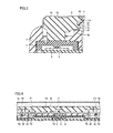
- FIG. 3 is a schematic cross-sectional view showing a portion around the switch mechanism along the line III-III in Fig. 1 . Namely, it is a figure of the portion around the switch mechanism in the cross-sectional view in a direction of a shorter side of lower housing 10.
- a switch portion 4 is arranged under key top portion 3b of HOME button 15j. Switch portion 4 is arranged in the inside of housing portion 2. Switch portion 4 is constructed such that it can be pressed in response to pressing of partial surface S of key top portion 3b.
- Key rubber (a biasing portion) 5 is arranged between key top portion 3b and switch portion 4. Key rubber (biasing portion) 5 is constructed to be able to bias key top portion 3b in a direction opposite to the direction of pressing. Key rubber (biasing portion) 5 is formed of rubber which is an elastic body, and it is constructed to be able to bias key top portion 3b with elastic force of rubber.
- Housing portion 2 has a support portion 2a, a side support portion 2b, and a contact portion 2c.
- Support portion 2a is constructed to support key top portion 3b from a direction opposite to the direction of pressing key top portion 3b when partial surface S of key top portion 3b is pressed.
- Support portion 2a is in a bent shape.
- lower front part 11 of lower housing 10 forming housing portion 2 has a restriction member 11b.
- Restriction member 11b is formed to protrude toward a side surface of key top portion 3b. Restriction member 11b is in a bent shape from an upper surface to a lower surface.
- Side support portion 2b and contact portion 2c are provided in restriction member 11b.
- Side support portion 2b is provided at a side surface of restriction member 11b having a bent shape.
- Contact portion 2c is provided at a lower surface of restriction member 11b.
- Side support portion 2b is constructed to tilt key top portion 3b by supporting key top portion 3b from a side in a direction intersecting the direction of pressing key top portion 3b when partial surface S of key top portion 3b is pressed.
- Side support portion 2b is constructed to support key top portion 3b from the direction intersecting the direction of pressing key top portion 3b.
- Side support portion 2b is constructed to restrict displacement of key top portion 3b toward restriction member 11b.
- housing portion 2 is constructed such that key top portion 3b is tilted while a position where side support portion 2b and key top portion 3b are in contact with each other is varied when partial surface S of key top portion 3b is pressed.
- Contact portion 2c is constructed to support key top portion 3b from the direction of pressing down key top portion 3b when partial surface S of key top portion 3b is pressed.
- Contact portion 2c is constructed to be able to restrict displacement of key top portion 3b in the direction opposite to the direction of pressing when partial surface S of key top portion 3b is pressed.
- housing portion 2 is constructed such that key top portion 3b is tilted while a position where contact portion 2c and key top portion 3b are in contact with each other is varied when partial surface S of key top portion 3b is pressed.
- switch portion 4 is arranged such that it is pressed by key top portion 3b as key top portion 3b is tilted while it is supported by both of side support portion 2b and contact portion 2c when partial surface S of key top portion 3b is pressed.
- Each afkey top portions 3a to 3c of respective SELECT button 15i, HOME button 15j, and START button 15k has an engagement portion 31, a falling-off prevention portion 32, and a cover portion 33.
- Engagement portion 31 is formed to protrude sideward in each of key top portions 3a to 3c.
- Engagement portion 31 is formed such that its tip end is in an arc shape in a cross-sectional view.
- Engagement portion 31 has a linear portion extending straight between the tip end and a root.
- Engagement portion 31 is arranged closer to partial surface S of key top portion 3b than support portion 2a.
- Side support portion 2b and contact portion 2c are arranged closer to partial surface S of key top portion 3b than engagement portion 31.
- falling-off prevention portion 32 is formed to protrude downward in each of key top portions 3a to 3c. Falling-off prevention portion 32 is formed to have a tip end in a claw shape. Falling-off prevention portion 32 is locked to lower front part 11 of housing portion 2.
- cover portion 33 forms a part of partial surface S of key top portion 3b.
- a side surface portion having a planar shape is provided between engagement portion 31 and cover portion 33.
- Restriction member 11b lies between engagement portion 31 and cover portion 33.
- Key top portion 3b is constructed to be supported by side support portion 2b between engagement portion 31 and cover portion 33.
- lower front part 11 has a first locking hole T1, a second locking hole T2, and an insertion hole T3.
- first locking hole T1 is formed to open such that engagement portion 31 can be inserted therein.
- second locking hole T2 is formed such that falling-off prevention portion 32 can be inserted therein.
- insertion hole T3 is constructed such that a lower end of each of key top portions 3a to 3c can be inserted therethrough.
- key top portion 3a of SELECT button 15i, key top portion 3b of HOME button 15j, and key top portion 3c of START button 15k are arranged at an end portion of main surface 10a of lower housing 10.
- the switch mechanism is arranged in a part of the peripheral portion of housing portion 2.
- a locking groove 10b is formed at an end portion of lower front part 11. Key top portion 3a of SELECT button 15i, key top portion 3b of HOME button 15j, and key top portion 3c of START button 15k are inserted as aligned in locking groove 10b.
- First locking hole T1, second locking hole T2, and insertion hole T3 are formed in an inner peripheral surface of locking groove 10b.
- First locking hole T1 is formed in a side surface of locking groove 10b on a side of lower LCD 13.
- Second locking hole T2 and insertion hole T3 are formed in a bottom surface of locking groove 10b.
- Engagement portion 31 of each of SELECT button 15i., HOME button 15j, and START button 15k is inserted in first locking hole T1 and falling-off prevention portion 32 is inserted in and locked to second locking hole T2, so that key top portions 3a to 3c are locked to lower front part 11.
- key rubber (biasing portion) 5 is arranged on a back surface 10c of lower front part 11.
- Key rubber (biasing portion) 5 is arranged at an end portion of lower front part 11 opposite to lower protrusion portion 11a.
- Key rubber (biasing portion) 5 has two engagement through holes 5a.
- a lower protrusion portion 11c formed on back surface 10c of lower front part 11 is inserted in each of two engagement through holes 5a.
- Key rubber (biasing portion) 5 is formed such that it can be pressed by each of key top portions 3 a to 3c inserted through insertion hole T3.
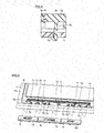
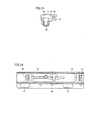
- key top portions 3a to 3c A construction of key top portions 3a to 3c will be described in further detail with reference to Figs. 10 to 14 .
- key top portion 3a of SELECT button 15i will be described.
- Partial surface S of each of key top portions 3a to 3c has a substantially rectangular shape.
- Engagement portion 31 is formed at each of opposing end portions along a longitudinal direction, at the lower surface of key top portion 3 a. Engagement portion 31 has a portion extending downward from the lower surface of key top portion 3a and a portion extending therefrom along a shorter side toward its one end. Namely, engagement portion 31 is bent. Falling-off prevention portion 32 is formed at each of the opposing end portions of the longitudinal direction, at the lower surface of key top portion 3a. Each falling-off prevention portion 32 has, at its tip end, a portion extending outward along the longitudinal direction of key top portion 3a.
- Key top portion 3b of START button 15k is also similar in construction to key top portion 3a of SELECT button 15i.
- key top portion 3b of HOME button 15j is different in having one engagement portion 31 in a central portion of the longitudinal direction as shown in Fig. 7 , it is otherwise similar in construction to key top portion 3a of SELECT button 15i.
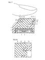
- key top portion 3b Since key top portion 3b is pressed in an oblique direction X2 because it is provided at the peripheral portion of housing portion 2, not only force F1 pressing down vertically but also force F2 pressing to the right in the horizontal direction are applied to key top portion 3b. Though key top portion 3b attempts to move in a right direction owing to this force F2 in the right direction, movement thereof is restricted by restriction member 11b. Then, side support portion 2b supports key top portion 3b from the side. Namely, side support portion 2b supports key top portion 3b from a direction X3 intersecting direction X1 of pressing key top portion 3b. Then, key top portion 3b is pressed down, with side support portion 2b serving as a fulcrum. Thus, key top portion 3b is tilted. Accordingly, a seesaw structure is implemented as side support portion 2b supports key top portion 3b from the side. Then, switch portion 4 is pressed by a lower end of key top portion 3b, with key rubber (biasing portion) 5 being
- key top portion 3b is tilted while being in contact with both of side support portion 2b and contact portion 2c.
- key top portion 3b is tilted while both of a position where key top portion 3b and side support portion 2b are in contact with each other and a position where key top portion 3b and contact portion 2c are in contact with each other are varied. More specifically, key top portion 3b is tilted while a position where key top portion 3b and side support portion 2b are in contact with each other moves upward along the side surface of key top portion 3b and a position where key top portion 3b and contact portion 2c are in contact with each other moves to the right along the lower surface of restriction member 11b.
- the switch mechanism may be constructed such that key top portion 3a returns to a position before being pressed, owing to elastic force of key rubber (biasing portion) 5 has been described above, limitation thereto is not intended.
- the switch mechanism may be constructed such that key top portion 3a returns to a position before being pressed, owing to elastic force of key top portion 3b.
- the switch mechanism may be constructed such that key top portion 3 a returns to a position before being pressed, owing to elastic force of switch portion 4.
- the switch mechanism is applied to a button provided at the end of housing portion 2. When such a button is pressed, force in the horizontal direction is applied to the button without operator's particular intention.
- side support portion 2b supports key top portion 3b from the side.
- key top portion 3b is obliquely pressed, and hence force pressing key top portion 3b acts not only in direction X1 of pressing key top portion 3b but also on the side of key top portion 3b. Therefore, with support of key top portion 3b from the side by side support portion 2b, key top portion 3b can be tilted while it is supported by side support portion 2b. Therefore, a switch mechanism of which key top portion 3b can be tilted with a simple mechanism without using a pin can be implemented.
- housing portion 2 is constructed such that key top portion 3b is tilted while a position where side support portion 2b and key top portion 3b are in contact with each other is varied when partial surface S of key top portion 3b is pressed. Therefore, when partial surface S of key top portion 3b is pressed, key top portion 3b can be tilted while a position where side support portion 2b and key top portion 3b are in contact with each other is varied. Thus, key top portion 3b can smoothly be tilted.
- housing portion 2 further includes contact portion 2c for supporting key top portion 3b from direction X1 of pressing key top portion 3b when partial surface S of key top portion 3b is pressed. Therefore, when partial surface S of key top portion 3b is pressed, contact portion 2c can support key top portion 3b from direction X1 of pressing key top portion 3b. Accordingly, displacement of the key top portion in direction X4 opposite to direction X1 of pressing can be suppressed by contact portion 2c. Thus, key top portion 3b can be tilted in a stable manner.
- housing portion 2 is constructed such that key top portion 3b is tilted while a position where contact portion 2c and key top portion 3b are in contact with each other is varied when partial surface S of key top portion 3b is pressed. Therefore, when partial surface S of key top portion 3b is pressed, key top portion 3b can be tilted while a position where contact portion 2c and key top portion 3b are in contact with each other is varied. Thus, key top portion 3b can smoothly be tilted.
- housing portion 2 further includes support portion 2a for supporting key top portion 3b from direction X4 opposite to direction X1 of pressing key top portion 3b when partial surface S of key top portion 3b is pressed. Therefore, when partial surface S of key top portion 3b is pressed, key top portion 3b can be supported by support portion 2a from direction X4 opposite to direction X1 of pressing key top portion 3b. Thus, key top portion 3b can smoothly be tilted.
- key top portion 3b further includes engagement portion 31 formed to protrude sideward from key top portion 3b and cover portion 33 forming a part of partial surface S of key top portion 3b.
- Key top portion 3b is constructed to be supported by side support portion 2b between engagement portion 31 and cover portion 33. Therefore, since side support portion 2b lies between engagement portion 31 and cover portion 33, falling off of key top portion 3b from housing portion 2 can be suppressed.
- cover portion 33 can cover side support portion 2b, exposure of side support portion 2b can be suppressed.
- switch portion 4 is arranged to be pressed by key top portion 3b as key top portion 3b is tilted while it is supported by both of side support portion 2b and contact portion 2c when partial surface S of key top portion 3b is pressed.
- switch portion 4 can be pressed in.
- key rubber (biasing portion) 5 which is arranged between key top portion 3b and switch portion 4 and capable of biasing key top portion 3b in direction X4 opposite to direction X1 of pressing is further provided. Key rubber (biasing portion) 5 can bias key top portion 3b in direction X4 opposite to direction X1 of pressing. Thus, key rubber (biasing portion) 5 can return key top portion 3b to a position before pressing.
- the switch mechanism further includes falling-off prevention portion 32 provided in key top portion 3b, and falling-off prevention portion 32 is locked to housing portion 2. Therefore, falling-off prevention portion 32 can prevent key top portion 3b from falling off from housing portion 2.
- Game device I includes the switch mechanism described above.
- game device 1 including the switch mechanism of which key top portions 3a to 3c can be tilted with a simple mechanism can be obtained.
- the switch mechanism is arranged in a part of the peripheral portion of housing portion 2. Therefore, at the peripheral portion of housing portion 2, key top portions 3a to 3c can be tilted outward of housing portion 2. Thus, operability of key top portions 3a to 3c can be improved.
- the exemplary embodiments can be applied, for example, also to the R button and the L button provided at the shoulder portions of the housing.
- the switch mechanism is applicable to various electronic devices.
- a mobile phone, a PDA (Personal Digital Assistant), a personal computer, and the like are exemplified as the electronic devices.
- a controller for the game device is also included in the electronic devices.
Landscapes
- Engineering & Computer Science (AREA)
- Computer Hardware Design (AREA)
- Theoretical Computer Science (AREA)
- Physics & Mathematics (AREA)
- Human Computer Interaction (AREA)
- General Engineering & Computer Science (AREA)
- General Physics & Mathematics (AREA)
- Mathematical Physics (AREA)
- Switches With Compound Operations (AREA)
- Mechanisms For Operating Contacts (AREA)
- Rotary Switch, Piano Key Switch, And Lever Switch (AREA)
Applications Claiming Priority (1)
| Application Number | Priority Date | Filing Date | Title |
|---|---|---|---|
| JP2012157432A JP2014022097A (ja) | 2012-07-13 | 2012-07-13 | スイッチ機構および電子装置 |
Publications (3)
| Publication Number | Publication Date |
|---|---|
| EP2685345A2 true EP2685345A2 (fr) | 2014-01-15 |
| EP2685345A3 EP2685345A3 (fr) | 2016-04-13 |
| EP2685345B1 EP2685345B1 (fr) | 2020-02-19 |
Family
ID=48782871
Family Applications (1)
| Application Number | Title | Priority Date | Filing Date |
|---|---|---|---|
| EP13173841.1A Active EP2685345B1 (fr) | 2012-07-13 | 2013-06-26 | Mécanisme de commutation et dispositif électronique |
Country Status (3)
| Country | Link |
|---|---|
| US (1) | US9087660B2 (fr) |
| EP (1) | EP2685345B1 (fr) |
| JP (1) | JP2014022097A (fr) |
Cited By (1)
| Publication number | Priority date | Publication date | Assignee | Title |
|---|---|---|---|---|
| IT201900016256A1 (it) * | 2019-09-13 | 2021-03-13 | Vimercati Spa | Interruttore a pulsante per pannelli porta di autoveicoli |
Families Citing this family (2)
| Publication number | Priority date | Publication date | Assignee | Title |
|---|---|---|---|---|
| JP6311587B2 (ja) * | 2014-12-04 | 2018-04-18 | 株式会社デンソー | 車両用表示操作デバイス |
| WO2025090863A1 (fr) * | 2023-10-27 | 2025-05-01 | Valve Corporation | Dispositif de commande résistant aux chutes |
Citations (1)
| Publication number | Priority date | Publication date | Assignee | Title |
|---|---|---|---|---|
| JPH0442029U (fr) | 1990-08-09 | 1992-04-09 |
Family Cites Families (9)
| Publication number | Priority date | Publication date | Assignee | Title |
|---|---|---|---|---|
| JPS58176341U (ja) * | 1982-05-20 | 1983-11-25 | エスエムケイ株式会社 | 押ボタンスイツチ |
| JPS60183335U (ja) * | 1984-05-10 | 1985-12-05 | 三菱電機株式会社 | 押釦装置 |
| JPH0442029A (ja) | 1990-06-06 | 1992-02-12 | Enplas Corp | 力覚センサー用自動検査装置 |
| JPH0492349U (fr) * | 1990-12-27 | 1992-08-11 | ||
| JP4298871B2 (ja) * | 1999-10-08 | 2009-07-22 | 矢崎総業株式会社 | 表示画面用スイッチ |
| US7625286B2 (en) | 2004-05-06 | 2009-12-01 | Sony Computer Entertainment Inc. | Electronic device and a game controller |
| JP2008269828A (ja) * | 2007-04-17 | 2008-11-06 | Matsushita Electric Ind Co Ltd | 多連型複合スイッチおよびその製造方法 |
| US8847890B2 (en) * | 2011-01-04 | 2014-09-30 | Synaptics Incorporated | Leveled touchsurface with planar translational responsiveness to vertical travel |
| US8309870B2 (en) * | 2011-01-04 | 2012-11-13 | Cody George Peterson | Leveled touchsurface with planar translational responsiveness to vertical travel |
-
2012
- 2012-07-13 JP JP2012157432A patent/JP2014022097A/ja active Pending
-
2013
- 2013-06-26 EP EP13173841.1A patent/EP2685345B1/fr active Active
- 2013-06-28 US US13/930,098 patent/US9087660B2/en active Active
Patent Citations (1)
| Publication number | Priority date | Publication date | Assignee | Title |
|---|---|---|---|---|
| JPH0442029U (fr) | 1990-08-09 | 1992-04-09 |
Cited By (1)
| Publication number | Priority date | Publication date | Assignee | Title |
|---|---|---|---|---|
| IT201900016256A1 (it) * | 2019-09-13 | 2021-03-13 | Vimercati Spa | Interruttore a pulsante per pannelli porta di autoveicoli |
Also Published As
| Publication number | Publication date |
|---|---|
| US9087660B2 (en) | 2015-07-21 |
| EP2685345B1 (fr) | 2020-02-19 |
| US20140014485A1 (en) | 2014-01-16 |
| EP2685345A3 (fr) | 2016-04-13 |
| JP2014022097A (ja) | 2014-02-03 |
Similar Documents
| Publication | Publication Date | Title |
|---|---|---|
| US8396521B2 (en) | Antenna cover and operating section for portable terminal device | |
| JP5218799B2 (ja) | カバー及び筐体 | |
| US20090264160A1 (en) | Electronic device with display and mobile phone | |
| JP5060990B2 (ja) | スタンド及び電子機器 | |
| CN1950132A (zh) | 电子装置及游戏控制器 | |
| US10354816B2 (en) | Operating device | |
| US7751555B2 (en) | Angle variable mechanism and desktop apparatus | |
| JP2016051309A (ja) | ドッキング装置 | |
| EP2685345B1 (fr) | Mécanisme de commutation et dispositif électronique | |
| US8767392B2 (en) | Portable electronic device | |
| US8035051B2 (en) | Electronic device | |
| US8570759B2 (en) | Controller and portable electronic apparatus | |
| US20080060929A1 (en) | Operating piece unit for switch and electronic apparatus | |
| US20030171137A1 (en) | Electronic device | |
| US20160087370A1 (en) | Electrical connection systems | |
| JP2015215822A (ja) | カバーおよびカバー付情報処理装置 | |
| KR101346572B1 (ko) | 휴대 기기용 케이스 | |
| JP4890586B2 (ja) | 操作装置及び携帯情報端末 | |
| JP4843575B2 (ja) | チルト構造および電子機器 | |
| CN212880991U (zh) | 一种用于游戏手柄按键的导轨组合结构 | |
| US20090261993A1 (en) | Keyboard | |
| KR101376610B1 (ko) | 휴대 단말기 | |
| JP3893095B2 (ja) | バッテリパックを具えた携帯電話機 | |
| CN222734466U (zh) | 可拆卸式鼠标模块及包括其的电子装置 | |
| JP7584695B1 (ja) | 携帯端末ケース |
Legal Events
| Date | Code | Title | Description |
|---|---|---|---|
| PUAI | Public reference made under article 153(3) epc to a published international application that has entered the european phase |
Free format text: ORIGINAL CODE: 0009012 |
|
| AK | Designated contracting states |
Kind code of ref document: A2 Designated state(s): AL AT BE BG CH CY CZ DE DK EE ES FI FR GB GR HR HU IE IS IT LI LT LU LV MC MK MT NL NO PL PT RO RS SE SI SK SM TR |
|
| AX | Request for extension of the european patent |
Extension state: BA ME |
|
| PUAL | Search report despatched |
Free format text: ORIGINAL CODE: 0009013 |
|
| AK | Designated contracting states |
Kind code of ref document: A3 Designated state(s): AL AT BE BG CH CY CZ DE DK EE ES FI FR GB GR HR HU IE IS IT LI LT LU LV MC MK MT NL NO PL PT RO RS SE SI SK SM TR |
|
| AX | Request for extension of the european patent |
Extension state: BA ME |
|
| RIC1 | Information provided on ipc code assigned before grant |
Ipc: G06F 1/16 20060101AFI20160310BHEP |
|
| 17P | Request for examination filed |
Effective date: 20160930 |
|
| RBV | Designated contracting states (corrected) |
Designated state(s): AL AT BE BG CH CY CZ DE DK EE ES FI FR GB GR HR HU IE IS IT LI LT LU LV MC MK MT NL NO PL PT RO RS SE SI SK SM TR |
|
| STAA | Information on the status of an ep patent application or granted ep patent |
Free format text: STATUS: EXAMINATION IS IN PROGRESS |
|
| 17Q | First examination report despatched |
Effective date: 20180503 |
|
| GRAP | Despatch of communication of intention to grant a patent |
Free format text: ORIGINAL CODE: EPIDOSNIGR1 |
|
| STAA | Information on the status of an ep patent application or granted ep patent |
Free format text: STATUS: GRANT OF PATENT IS INTENDED |
|
| INTG | Intention to grant announced |
Effective date: 20191107 |
|
| RAP1 | Party data changed (applicant data changed or rights of an application transferred) |
Owner name: NINTENDO CO., LTD. |
|
| GRAS | Grant fee paid |
Free format text: ORIGINAL CODE: EPIDOSNIGR3 |
|
| GRAA | (expected) grant |
Free format text: ORIGINAL CODE: 0009210 |
|
| STAA | Information on the status of an ep patent application or granted ep patent |
Free format text: STATUS: THE PATENT HAS BEEN GRANTED |
|
| AK | Designated contracting states |
Kind code of ref document: B1 Designated state(s): AL AT BE BG CH CY CZ DE DK EE ES FI FR GB GR HR HU IE IS IT LI LT LU LV MC MK MT NL NO PL PT RO RS SE SI SK SM TR |
|
| REG | Reference to a national code |
Ref country code: GB Ref legal event code: FG4D |
|
| REG | Reference to a national code |
Ref country code: CH Ref legal event code: EP |
|
| REG | Reference to a national code |
Ref country code: DE Ref legal event code: R096 Ref document number: 602013065910 Country of ref document: DE |
|
| REG | Reference to a national code |
Ref country code: AT Ref legal event code: REF Ref document number: 1235681 Country of ref document: AT Kind code of ref document: T Effective date: 20200315 |
|
| REG | Reference to a national code |
Ref country code: IE Ref legal event code: FG4D |
|
| REG | Reference to a national code |
Ref country code: NL Ref legal event code: MP Effective date: 20200219 |
|
| PG25 | Lapsed in a contracting state [announced via postgrant information from national office to epo] |
Ref country code: FI Free format text: LAPSE BECAUSE OF FAILURE TO SUBMIT A TRANSLATION OF THE DESCRIPTION OR TO PAY THE FEE WITHIN THE PRESCRIBED TIME-LIMIT Effective date: 20200219 Ref country code: RS Free format text: LAPSE BECAUSE OF FAILURE TO SUBMIT A TRANSLATION OF THE DESCRIPTION OR TO PAY THE FEE WITHIN THE PRESCRIBED TIME-LIMIT Effective date: 20200219 Ref country code: NO Free format text: LAPSE BECAUSE OF FAILURE TO SUBMIT A TRANSLATION OF THE DESCRIPTION OR TO PAY THE FEE WITHIN THE PRESCRIBED TIME-LIMIT Effective date: 20200519 |
|
| REG | Reference to a national code |
Ref country code: LT Ref legal event code: MG4D |
|
| PG25 | Lapsed in a contracting state [announced via postgrant information from national office to epo] |
Ref country code: HR Free format text: LAPSE BECAUSE OF FAILURE TO SUBMIT A TRANSLATION OF THE DESCRIPTION OR TO PAY THE FEE WITHIN THE PRESCRIBED TIME-LIMIT Effective date: 20200219 Ref country code: BG Free format text: LAPSE BECAUSE OF FAILURE TO SUBMIT A TRANSLATION OF THE DESCRIPTION OR TO PAY THE FEE WITHIN THE PRESCRIBED TIME-LIMIT Effective date: 20200519 Ref country code: GR Free format text: LAPSE BECAUSE OF FAILURE TO SUBMIT A TRANSLATION OF THE DESCRIPTION OR TO PAY THE FEE WITHIN THE PRESCRIBED TIME-LIMIT Effective date: 20200520 Ref country code: IS Free format text: LAPSE BECAUSE OF FAILURE TO SUBMIT A TRANSLATION OF THE DESCRIPTION OR TO PAY THE FEE WITHIN THE PRESCRIBED TIME-LIMIT Effective date: 20200619 Ref country code: SE Free format text: LAPSE BECAUSE OF FAILURE TO SUBMIT A TRANSLATION OF THE DESCRIPTION OR TO PAY THE FEE WITHIN THE PRESCRIBED TIME-LIMIT Effective date: 20200219 Ref country code: LV Free format text: LAPSE BECAUSE OF FAILURE TO SUBMIT A TRANSLATION OF THE DESCRIPTION OR TO PAY THE FEE WITHIN THE PRESCRIBED TIME-LIMIT Effective date: 20200219 |
|
| PG25 | Lapsed in a contracting state [announced via postgrant information from national office to epo] |
Ref country code: NL Free format text: LAPSE BECAUSE OF FAILURE TO SUBMIT A TRANSLATION OF THE DESCRIPTION OR TO PAY THE FEE WITHIN THE PRESCRIBED TIME-LIMIT Effective date: 20200219 |
|
| PG25 | Lapsed in a contracting state [announced via postgrant information from national office to epo] |
Ref country code: CZ Free format text: LAPSE BECAUSE OF FAILURE TO SUBMIT A TRANSLATION OF THE DESCRIPTION OR TO PAY THE FEE WITHIN THE PRESCRIBED TIME-LIMIT Effective date: 20200219 Ref country code: RO Free format text: LAPSE BECAUSE OF FAILURE TO SUBMIT A TRANSLATION OF THE DESCRIPTION OR TO PAY THE FEE WITHIN THE PRESCRIBED TIME-LIMIT Effective date: 20200219 Ref country code: SK Free format text: LAPSE BECAUSE OF FAILURE TO SUBMIT A TRANSLATION OF THE DESCRIPTION OR TO PAY THE FEE WITHIN THE PRESCRIBED TIME-LIMIT Effective date: 20200219 Ref country code: PT Free format text: LAPSE BECAUSE OF FAILURE TO SUBMIT A TRANSLATION OF THE DESCRIPTION OR TO PAY THE FEE WITHIN THE PRESCRIBED TIME-LIMIT Effective date: 20200712 Ref country code: SM Free format text: LAPSE BECAUSE OF FAILURE TO SUBMIT A TRANSLATION OF THE DESCRIPTION OR TO PAY THE FEE WITHIN THE PRESCRIBED TIME-LIMIT Effective date: 20200219 Ref country code: DK Free format text: LAPSE BECAUSE OF FAILURE TO SUBMIT A TRANSLATION OF THE DESCRIPTION OR TO PAY THE FEE WITHIN THE PRESCRIBED TIME-LIMIT Effective date: 20200219 Ref country code: LT Free format text: LAPSE BECAUSE OF FAILURE TO SUBMIT A TRANSLATION OF THE DESCRIPTION OR TO PAY THE FEE WITHIN THE PRESCRIBED TIME-LIMIT Effective date: 20200219 Ref country code: EE Free format text: LAPSE BECAUSE OF FAILURE TO SUBMIT A TRANSLATION OF THE DESCRIPTION OR TO PAY THE FEE WITHIN THE PRESCRIBED TIME-LIMIT Effective date: 20200219 Ref country code: ES Free format text: LAPSE BECAUSE OF FAILURE TO SUBMIT A TRANSLATION OF THE DESCRIPTION OR TO PAY THE FEE WITHIN THE PRESCRIBED TIME-LIMIT Effective date: 20200219 |
|
| REG | Reference to a national code |
Ref country code: AT Ref legal event code: MK05 Ref document number: 1235681 Country of ref document: AT Kind code of ref document: T Effective date: 20200219 |
|
| REG | Reference to a national code |
Ref country code: DE Ref legal event code: R097 Ref document number: 602013065910 Country of ref document: DE |
|
| PLBE | No opposition filed within time limit |
Free format text: ORIGINAL CODE: 0009261 |
|
| STAA | Information on the status of an ep patent application or granted ep patent |
Free format text: STATUS: NO OPPOSITION FILED WITHIN TIME LIMIT |
|
| 26N | No opposition filed |
Effective date: 20201120 |
|
| PG25 | Lapsed in a contracting state [announced via postgrant information from national office to epo] |
Ref country code: AT Free format text: LAPSE BECAUSE OF FAILURE TO SUBMIT A TRANSLATION OF THE DESCRIPTION OR TO PAY THE FEE WITHIN THE PRESCRIBED TIME-LIMIT Effective date: 20200219 Ref country code: IT Free format text: LAPSE BECAUSE OF FAILURE TO SUBMIT A TRANSLATION OF THE DESCRIPTION OR TO PAY THE FEE WITHIN THE PRESCRIBED TIME-LIMIT Effective date: 20200219 Ref country code: MC Free format text: LAPSE BECAUSE OF FAILURE TO SUBMIT A TRANSLATION OF THE DESCRIPTION OR TO PAY THE FEE WITHIN THE PRESCRIBED TIME-LIMIT Effective date: 20200219 |
|
| REG | Reference to a national code |
Ref country code: CH Ref legal event code: PL |
|
| PG25 | Lapsed in a contracting state [announced via postgrant information from national office to epo] |
Ref country code: PL Free format text: LAPSE BECAUSE OF FAILURE TO SUBMIT A TRANSLATION OF THE DESCRIPTION OR TO PAY THE FEE WITHIN THE PRESCRIBED TIME-LIMIT Effective date: 20200219 Ref country code: SI Free format text: LAPSE BECAUSE OF FAILURE TO SUBMIT A TRANSLATION OF THE DESCRIPTION OR TO PAY THE FEE WITHIN THE PRESCRIBED TIME-LIMIT Effective date: 20200219 |
|
| PG25 | Lapsed in a contracting state [announced via postgrant information from national office to epo] |
Ref country code: LU Free format text: LAPSE BECAUSE OF NON-PAYMENT OF DUE FEES Effective date: 20200626 |
|
| REG | Reference to a national code |
Ref country code: BE Ref legal event code: MM Effective date: 20200630 |
|
| PG25 | Lapsed in a contracting state [announced via postgrant information from national office to epo] |
Ref country code: CH Free format text: LAPSE BECAUSE OF NON-PAYMENT OF DUE FEES Effective date: 20200630 Ref country code: IE Free format text: LAPSE BECAUSE OF NON-PAYMENT OF DUE FEES Effective date: 20200626 Ref country code: LI Free format text: LAPSE BECAUSE OF NON-PAYMENT OF DUE FEES Effective date: 20200630 |
|
| PG25 | Lapsed in a contracting state [announced via postgrant information from national office to epo] |
Ref country code: BE Free format text: LAPSE BECAUSE OF NON-PAYMENT OF DUE FEES Effective date: 20200630 |
|
| PG25 | Lapsed in a contracting state [announced via postgrant information from national office to epo] |
Ref country code: TR Free format text: LAPSE BECAUSE OF FAILURE TO SUBMIT A TRANSLATION OF THE DESCRIPTION OR TO PAY THE FEE WITHIN THE PRESCRIBED TIME-LIMIT Effective date: 20200219 Ref country code: MT Free format text: LAPSE BECAUSE OF FAILURE TO SUBMIT A TRANSLATION OF THE DESCRIPTION OR TO PAY THE FEE WITHIN THE PRESCRIBED TIME-LIMIT Effective date: 20200219 Ref country code: CY Free format text: LAPSE BECAUSE OF FAILURE TO SUBMIT A TRANSLATION OF THE DESCRIPTION OR TO PAY THE FEE WITHIN THE PRESCRIBED TIME-LIMIT Effective date: 20200219 |
|
| PG25 | Lapsed in a contracting state [announced via postgrant information from national office to epo] |
Ref country code: MK Free format text: LAPSE BECAUSE OF FAILURE TO SUBMIT A TRANSLATION OF THE DESCRIPTION OR TO PAY THE FEE WITHIN THE PRESCRIBED TIME-LIMIT Effective date: 20200219 Ref country code: AL Free format text: LAPSE BECAUSE OF FAILURE TO SUBMIT A TRANSLATION OF THE DESCRIPTION OR TO PAY THE FEE WITHIN THE PRESCRIBED TIME-LIMIT Effective date: 20200219 |
|
| P01 | Opt-out of the competence of the unified patent court (upc) registered |
Effective date: 20230428 |
|
| PGFP | Annual fee paid to national office [announced via postgrant information from national office to epo] |
Ref country code: DE Payment date: 20250429 Year of fee payment: 13 |
|
| PGFP | Annual fee paid to national office [announced via postgrant information from national office to epo] |
Ref country code: GB Payment date: 20250508 Year of fee payment: 13 |
|
| PGFP | Annual fee paid to national office [announced via postgrant information from national office to epo] |
Ref country code: FR Payment date: 20250508 Year of fee payment: 13 |