EP2685541A1 - Vorrichtungen, Systeme und Verfahren zur Batteriezellenfehlererkennung - Google Patents
Vorrichtungen, Systeme und Verfahren zur Batteriezellenfehlererkennung Download PDFInfo
- Publication number
- EP2685541A1 EP2685541A1 EP13176291.6A EP13176291A EP2685541A1 EP 2685541 A1 EP2685541 A1 EP 2685541A1 EP 13176291 A EP13176291 A EP 13176291A EP 2685541 A1 EP2685541 A1 EP 2685541A1
- Authority
- EP
- European Patent Office
- Prior art keywords
- battery cell
- battery
- voltage
- circuitry
- conductive foil
- Prior art date
- Legal status (The legal status is an assumption and is not a legal conclusion. Google has not performed a legal analysis and makes no representation as to the accuracy of the status listed.)
- Granted
Links
- 238000000034 method Methods 0.000 title claims description 12
- 238000001514 detection method Methods 0.000 title description 4
- 239000011888 foil Substances 0.000 claims abstract description 54
- 238000005259 measurement Methods 0.000 claims abstract description 20
- 238000012544 monitoring process Methods 0.000 claims abstract description 14
- 230000000712 assembly Effects 0.000 claims description 31
- 238000000429 assembly Methods 0.000 claims description 31
- 238000007599 discharging Methods 0.000 claims description 5
- 229920000642 polymer Polymers 0.000 claims description 5
- WHXSMMKQMYFTQS-UHFFFAOYSA-N Lithium Chemical compound [Li] WHXSMMKQMYFTQS-UHFFFAOYSA-N 0.000 claims description 4
- 229910052744 lithium Inorganic materials 0.000 claims description 4
- 239000012636 effector Substances 0.000 description 14
- 238000012545 processing Methods 0.000 description 13
- 230000033001 locomotion Effects 0.000 description 4
- 238000004891 communication Methods 0.000 description 3
- 230000008878 coupling Effects 0.000 description 3
- 238000010168 coupling process Methods 0.000 description 3
- 238000005859 coupling reaction Methods 0.000 description 3
- 238000010586 diagram Methods 0.000 description 3
- 239000003792 electrolyte Substances 0.000 description 3
- 230000004044 response Effects 0.000 description 3
- 230000009471 action Effects 0.000 description 2
- 230000004913 activation Effects 0.000 description 2
- 230000006870 function Effects 0.000 description 2
- 230000004888 barrier function Effects 0.000 description 1
- 230000002146 bilateral effect Effects 0.000 description 1
- 230000005540 biological transmission Effects 0.000 description 1
- 239000004020 conductor Substances 0.000 description 1
- 229910052751 metal Inorganic materials 0.000 description 1
- 239000002184 metal Substances 0.000 description 1
- 238000012986 modification Methods 0.000 description 1
- 230000004048 modification Effects 0.000 description 1
- 230000000149 penetrating effect Effects 0.000 description 1
- 230000001681 protective effect Effects 0.000 description 1
- 230000001105 regulatory effect Effects 0.000 description 1
Images



Classifications
-
- H—ELECTRICITY
- H01—ELECTRIC ELEMENTS
- H01M—PROCESSES OR MEANS, e.g. BATTERIES, FOR THE DIRECT CONVERSION OF CHEMICAL ENERGY INTO ELECTRICAL ENERGY
- H01M10/00—Secondary cells; Manufacture thereof
- H01M10/42—Methods or arrangements for servicing or maintenance of secondary cells or secondary half-cells
- H01M10/4228—Leak testing of cells or batteries
-
- G—PHYSICS
- G01—MEASURING; TESTING
- G01R—MEASURING ELECTRIC VARIABLES; MEASURING MAGNETIC VARIABLES
- G01R31/00—Arrangements for testing electric properties; Arrangements for locating electric faults; Arrangements for electrical testing characterised by what is being tested not provided for elsewhere
- G01R31/36—Arrangements for testing, measuring or monitoring the electrical condition of accumulators or electric batteries, e.g. capacity or state of charge [SoC]
- G01R31/382—Arrangements for monitoring battery or accumulator variables, e.g. SoC
- G01R31/3835—Arrangements for monitoring battery or accumulator variables, e.g. SoC involving only voltage measurements
-
- H—ELECTRICITY
- H01—ELECTRIC ELEMENTS
- H01M—PROCESSES OR MEANS, e.g. BATTERIES, FOR THE DIRECT CONVERSION OF CHEMICAL ENERGY INTO ELECTRICAL ENERGY
- H01M10/00—Secondary cells; Manufacture thereof
- H01M10/42—Methods or arrangements for servicing or maintenance of secondary cells or secondary half-cells
- H01M10/48—Accumulators combined with arrangements for measuring, testing or indicating the condition of cells, e.g. the level or density of the electrolyte
-
- H—ELECTRICITY
- H01—ELECTRIC ELEMENTS
- H01M—PROCESSES OR MEANS, e.g. BATTERIES, FOR THE DIRECT CONVERSION OF CHEMICAL ENERGY INTO ELECTRICAL ENERGY
- H01M10/00—Secondary cells; Manufacture thereof
- H01M10/42—Methods or arrangements for servicing or maintenance of secondary cells or secondary half-cells
- H01M10/48—Accumulators combined with arrangements for measuring, testing or indicating the condition of cells, e.g. the level or density of the electrolyte
- H01M10/482—Accumulators combined with arrangements for measuring, testing or indicating the condition of cells, e.g. the level or density of the electrolyte for several batteries or cells simultaneously or sequentially
-
- H—ELECTRICITY
- H01—ELECTRIC ELEMENTS
- H01M—PROCESSES OR MEANS, e.g. BATTERIES, FOR THE DIRECT CONVERSION OF CHEMICAL ENERGY INTO ELECTRICAL ENERGY
- H01M50/00—Constructional details or processes of manufacture of the non-active parts of electrochemical cells other than fuel cells, e.g. hybrid cells
- H01M50/10—Primary casings; Jackets or wrappings
- H01M50/116—Primary casings; Jackets or wrappings characterised by the material
- H01M50/124—Primary casings; Jackets or wrappings characterised by the material having a layered structure
- H01M50/126—Primary casings; Jackets or wrappings characterised by the material having a layered structure comprising three or more layers
-
- H—ELECTRICITY
- H01—ELECTRIC ELEMENTS
- H01M—PROCESSES OR MEANS, e.g. BATTERIES, FOR THE DIRECT CONVERSION OF CHEMICAL ENERGY INTO ELECTRICAL ENERGY
- H01M10/00—Secondary cells; Manufacture thereof
- H01M10/42—Methods or arrangements for servicing or maintenance of secondary cells or secondary half-cells
- H01M10/425—Structural combination with electronic components, e.g. electronic circuits integrated to the outside of the casing
- H01M2010/4271—Battery management systems including electronic circuits, e.g. control of current or voltage to keep battery in healthy state, cell balancing
-
- Y—GENERAL TAGGING OF NEW TECHNOLOGICAL DEVELOPMENTS; GENERAL TAGGING OF CROSS-SECTIONAL TECHNOLOGIES SPANNING OVER SEVERAL SECTIONS OF THE IPC; TECHNICAL SUBJECTS COVERED BY FORMER USPC CROSS-REFERENCE ART COLLECTIONS [XRACs] AND DIGESTS
- Y02—TECHNOLOGIES OR APPLICATIONS FOR MITIGATION OR ADAPTATION AGAINST CLIMATE CHANGE
- Y02E—REDUCTION OF GREENHOUSE GAS [GHG] EMISSIONS, RELATED TO ENERGY GENERATION, TRANSMISSION OR DISTRIBUTION
- Y02E60/00—Enabling technologies; Technologies with a potential or indirect contribution to GHG emissions mitigation
- Y02E60/10—Energy storage using batteries
Definitions
- the present disclosure relates to battery cell monitoring and, more particularly, to devices, systems, and methods for detecting fault conditions at the battery cell level.
- Battery-powered devices are advantageous in that they obviate the need for cables coupling the device to an electrical outlet or external power source.
- a typical battery pack for a battery-powered device includes one or more battery cells coupled to one another via a powering circuit that provides electrical power to the device.
- Battery packs have been developed that include control and safety circuitry configured to monitor various characteristics of the battery cells, both collectively and individually, e.g., individual battery cell voltage, battery pack voltage, temperature, and/or current, such that conditions that may cause failure or damage to the individual battery cells, the battery pack, and/or the device, e.g., as a result of overvoltage, under-voltage, over-temperature, or over-current, may be averted.
- control and safety circuitry configured to monitor various characteristics of the battery cells, both collectively and individually, e.g., individual battery cell voltage, battery pack voltage, temperature, and/or current, such that conditions that may cause failure or damage to the individual battery cells, the battery pack, and/or the device, e.g., as a result of overvoltage, under-voltage, over-temperature, or over-current, may be averted.
- Control and safety circuitry is also utilized to detect battery cell failure, for example, by detecting excessive internal self-discharge, atypical impedance, or state of charge curve anomalies. However, in some instances, the control and safety circuitry may be unable to detect battery cell fault conditions at an early stage, e.g., before failure occurs.
- the systems and methods according to aspects of the present disclosure provide early detection of pre-failure fault conditions at the battery cell level so that battery cell failure and battery pack failure can be averted.
- a battery assembly generally including a battery cell, a pouch, and a conductive lead.
- the pouch encloses the battery cell and includes an inner insulative jacket, an outer insulative jacket, and a conductive foil disposed between the inner and outer insulative jackets.
- the conductive lead extends through the outer insulative jacket and is electrically coupled to the conductive foil.
- the conductive lead is configured to electrically couple to battery circuitry for monitoring a voltage on the conductive foil to determine a fault condition.
- the battery circuitry includes an analog to digital converter that is electrically coupled to the conductive lead and is configured to convert an analog voltage on the conductive lead into a digital voltage value.
- the battery circuit may further include a microcontroller, which preferably provides the analog to digital converter, having a central processing unit configured to evaluate the digital value for determining the fault condition.
- the battery circuit may include logic circuitry configured to determine whether a fault condition exists based on the voltage of the conductive lead.
- the logic circuitry may include a comparator that is configured to receive a voltage corresponding with the voltage of the conductive lead.
- the voltage may be the output from an analog to digital converter or may be analog values fed directly from the conductive lead.
- the comparator compares the voltage with a predetermined reference voltage value which may be zero or non-zero.
- the battery cell is a lithium polymer battery cell.
- the battery assembly further includes a pair of electrode terminals coupled to the battery cell and extending from the pouch.
- the battery circuitry is coupled to the electrode terminals and is configured to monitor characteristics of the battery cell and to regulate charging and discharging of the battery cell based on the monitored characteristics of the battery cell.
- the battery circuitry includes measurement circuitry configured to measure the voltage on the conductive foil and logic circuitry configured to determine whether the fault condition exits by comparing the voltage on the conductive foil to a predetermined voltage value.
- the predetermined voltage value may correspond to a zero voltage.
- the predetermined voltage value may correspond to a non-zero voltage threshold.
- the pouch is heat sealed about the battery cell.
- a method of monitoring fault conditions in a battery cell assembly is also provided in accordance with aspects the present disclosure.
- the battery assembly includes a battery cell and a pouch surrounding the battery cell.
- the pouch includes an inner insulative jacket, an outer insulative jacket, and a conductive foil disposed between the inner and outer insulative jackets.
- the method includes determining a voltage on the conductive foil, comparing the voltage on the conductive foil to a predetermined voltage value and, if the voltage on the conductive foil exceeds the predetermined voltage value, indicating a fault condition.
- the method further includes converting the voltage on the conductive foil to a digital voltage value corresponding to the voltage on the conductive foil.
- the predetermined voltage value may correspond to zero volts. Alternatively, the predetermined voltage value may correspond to a non-zero voltage.
- a battery assembly provided in accordance with aspects of the present disclosure includes a battery pack having a plurality of battery cells assemblies.
- Each battery cell assembly includes a battery cell and a pouch enclosing the battery cell.
- the pouch includes an inner insulative jacket, an outer insulative jacket, and a conductive foil disposed between the inner and outer insulative jackets.
- a conductive lead extends through the outer insulative jacket and is electrically coupled to the conductive foil.
- the battery assembly further includes battery circuitry including measurement circuitry electrically coupled to the conductive lead of each of the plurality of battery cell assemblies to measure a voltage of the conductive foil, and logic circuitry coupled to the measurement circuitry and configured to determine whether a fault condition exits based on the measured voltage of the conductive foil of each of the plurality of battery cell assemblies.
- the logic circuitry determined whether a fault condition exists by comparing the measured voltage of each of the plurality of battery cell assemblies to a predetermined voltage.
- the battery circuitry is coupled to electrode terminals of each of the battery cell assemblies.
- the battery circuitry is configured to monitor characteristics of the respective battery cells and to regulate charging and discharging of the battery cells based on the monitored characteristics.
- the battery cell of one or more of the battery cell assemblies is a lithium polymer battery cell.
- the predetermined voltage value may correspond to zero volts or may correspond to a non-zero voltage threshold.
- a plurality of analog to digital converters are provided.
- Each analog to digital converter is electrically coupled to one of the conductive leads and is configured to convert an analog voltage value from the conductive lead into a digital voltage value for output to the logic circuitry.
- a multiplexer is coupled to each of the conductive leads and is configured to alternatingly provide an analog voltage of each of the conductive leads.
- An analog to digital converter is configured to alternatingly receive the analog voltage of each battery cell assembly from the multiplexer and to convert the analog voltage into a digital voltage value for output to the logic circuitry.
- a battery assembly provided in accordance with aspects of the present disclosure includes a plurality of battery cell assemblies, each battery cell assembly comprising a battery cell, a pouch enclosing the battery cell that comprises an inner insulative jacket and an outer insulative jacket, a conductive foil disposed between the inner and outer insulative jackets and a conductive lead electronically coupled to the conductive foil and extending through the outer insulative jacket.
- the conductive lead of each battery cell assembly is configured to electronically couple with battery circuitry for monitoring the voltage on each conductive lead to determine a fault condition.
- the battery circuitry includes a microcontroller that provides one or more analog to digital converters and a central processing unit.
- Each conductive lead of each battery cell assembly may be coupled to an analog to digital converter for outputting digital values corresponding to the analog voltages to the central processing unit.
- each conductive lead of each battery cell assembly may be coupled to a multiplexer that is coupled to an analog to digital converter for outputting digital values corresponding to the analog voltages to the central processing unit.
- the central processing unit is configured to evaluate the digital voltage values to determine whether or not a fault condition exists in any of the battery cell assemblies.
- a surgical instrument provided in accordance with aspects of the present disclosure includes an electrosurgical instrument having a housing configured to engage with a battery assembly in accordance with the aforementioned aspects.
- the engagement is releasable.
- a shaft may be coupled to the housing at a proximal end thereof.
- An end effector including jaw members may be disposed at a distal end of the shaft.
- a generator may be provided that is preferably releasably engageable with a body portion of the housing and is preferably selectively removable from the body portion either in connection with the removal of the battery assembly or independently.
- the generator is disposed in operable communication with the battery assembly to provide electrosurgical energy to the end effector for electrosurgically treating tissue.
- one of the jaw members serves as an active or oscillating ultrasonic blade that is selectively activatable to ultrasonically treat tissue grasped between the jaw members.
- the generator may convert electrical energy provided by the battery assembly into a high voltage AC waveform that drives a transducer configured to convert electrical energy into mechanical energy that produces motion at the blade.
- the battery circuitry may be configured to disconnect faulted battery cell(s) and/or surrounding battery cell(s) from the remainder of the system and/or may be configured to disconnect all battery cell(s).
- Fig. 1 is a side, perspective view of a portable, battery-powered surgical instrument configured for use in accordance with some embodiments of the present disclosure
- Fig. 2 is a side, perspective view of another portable, battery-powered surgical instrument configured for use in accordance with other embodiments of the present disclosure
- Fig. 3 is a side, perspective view of a battery assembly provided in accordance with the present disclosure and configured for use with the instruments of Figs. 1 and 2 ;
- Fig. 4 is an exploded, perspective view of the battery assembly of Fig. 3 ;
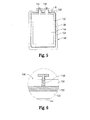
- Fig. 5 is a front, cross-sectional view of one of the battery cells of the battery assembly of Fig. 3 ;
- Fig. 6 is an enlarged view of the area of detail indicated as "6" in Fig. 5 ;
- Fig. 7 is a cross-sectional view of opposed ends of adjacent battery cells of the battery assembly of Fig. 3 ;
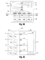
- Fig. 8A is a schematic diagram showing one configuration for monitoring the battery cells of the battery assembly of Fig. 3 ;
- Fig. 8B is a schematic diagram showing another configuration for monitoring the battery cells of the battery assembly of Fig. 3 ;
- Fig. 8C is a schematic diagram showing another configuration for monitoring the battery cells of the battery assembly of Fig. 3 .
- Fig. 1 depicts a portable, battery-powered electrosurgical instrument 2
- Fig. 2 depicts a portable, battery-powered ultrasonic surgical instrument 102.
- an electrosurgical instrument e.g., instrument 2
- an ultrasonic instrument e.g., instrument 102
- any other suitable battery-powered device e.g., a surgical instrument, handheld tool, electronic device, or the like.
- electrosurgical instrument 2 and ultrasonic instrument 102 are generally described.
- electrosurgical instrument 2 shown as an electrosurgical forceps, generally includes a housing 4, a battery assembly 18, an electrosurgical generator 28, a handle assembly 6, a rotating assembly 7, a shaft 8, a trigger assembly 10, a drive assembly (not shown), and an end effector assembly 12.
- End effector assembly 12 operatively connects to handle assembly 6 via the drive assembly (not shown) for imparting movement of one or both of jaw members 14, 16 of end effector assembly 12 between a spaced-apart position and an approximated position for grasping tissue therebetween.
- shaft 8 is coupled to housing 4 at proximal end 20 thereof and extends distally from housing 4 to define a longitudinal axis "A-A.”
- End effector assembly 12 including jaw members 14 and 16, is disposed at a distal end 22 of shaft 8.
- End effector assembly 12 is shown configured as a unilateral assembly wherein jaw member 16 is fixed relative to shaft 8 and jaw member 14 is pivotable relative to jaw member 16 and shaft 8 between the spaced-apart and approximated positions. However, this configuration may be reversed, e.g., wherein jaw member 14 is fixed relative to shaft 8 and jaw member 16 is pivotable relative to jaw member 14 and shaft 8.
- end effector assembly 12 may be configured as a bilateral assembly, e.g., wherein both jaw members 14, 16 are pivotable relative to one another and shaft 8 between the spaced-apart and approximated positions.
- Electrosurgical instrument 2 may be configured as a bipolar instrument. That is, each of the jaw members 14, 16 may include a respective seal plate 15, 17 that is configured to function as an active (or activatable) and/or return electrode. Each seal plate 15, 17 is electrically coupled to generator 28 via one or more electrical leads (not shown) that extend from generator 28, through shaft 8, and eventually coupling to one or both of seal plates 15, 17 for conducting energy through tissue grasped therebetween.
- forceps 2 may alternatively be configured as a monopolar instrument.
- Handle assembly 6 includes a moveable handle 40 that is movable relative to fixed handle portion 42 for moving jaw members 14, 16 of end effector assembly 12 between the spaced-apart and approximated positions.
- Rotating assembly 7 is rotatable in either direction about longitudinal axis "A-A" to rotate shaft 8 and, thus, end effector assembly 12 about longitudinal axis "A-A.”
- Trigger assembly 10 is in operable communication with a knife assembly (not shown) including a knife blade (not shown) that is selectively translatable between jaw members 14, 16 to cut tissue grasped therebetween, e.g., upon actuation of trigger 11 of trigger assembly 10.
- housing 4 is configured to releasably engage electrosurgical generator 28 and battery assembly 18.
- Generator 28 is releasably engagable with body portion 44 of housing 4, while battery assembly 18 is releasably engagable with fixed handle portion 42 of housing 4. More specifically, battery assembly 18 is configured to engage fixed handle portion 42 of housing 4 such that battery assembly 18 functions as the stationary handle of housing 4 to facilitate grasping of the forceps 2.
- Generator 28 releasably engages body portion 44 of housing 4 and may be selectively removable from body portion 44 either in connection with the removal of battery assembly 18 or independently.
- generator 28 When forceps 2 is assembled, generator 28 is disposed in operable communication with battery assembly 18 to provide electrosurgical energy to end effector 12 for electrosurgically treating tissue, e.g., to seal tissue, although forceps 2 may alternatively be configured to deliver any other suitable form of energy to tissue, e.g., thermal energy, microwave energy, light energy, etc.
- generator 28 may include suitable electronics that convert the electrical energy from battery assembly 18 into an RF energy waveform to energize one or both of jaw members 14, 16. That is, generator 28 may be configured to transmit RF energy to seal plate 15 of jaw member 14 and/or seal plate 17 of jaw member 16 to conduct energy therebetween for treating tissue.
- Activation switch 1 disposed on housing 4 is activatable for selectively enabling generator 28 to generate and subsequently transmit RF energy to seal plate 15 and/or seal plate 17 of jaw members 14, 16, respectively, for treating tissue grasped therebetween.
- ultrasonic instrument 102 includes components similar to that of forceps 2 shown in Fig. 1 , namely, a housing 104, a battery assembly 118, a generator 128, a handle assembly 106, a shaft 108, and an end effector assembly 112. Accordingly, only the difference between ultrasonic instrument 102 and forceps 2 ( Fig. 1 ) will be described below.
- Housing 104 is configured to releasably engage ultrasonic generator 128 and battery assembly 118.
- Shaft 108 extends distally from housing 104 to define longitudinal axis "B-B" and includes end effector assembly 112 disposed at distal end 122 thereof.
- One or both of jaw members 114 and 116 of end effector assembly 112 are movable relative to one another, e.g., upon actuation of moveable handle 124, between an open position and a clamping position for grasping tissue therebetween.
- one of the jaw members e.g., jaw member 116, serves as an active or oscillating ultrasonic blade that is selectively activatable to ultrasonically treat tissue grasped between jaw members 114, 116.
- Generator 128 includes a transducer (not shown) configured to convert electrical energy provided by battery assembly 118 into mechanical energy that produces motion at the end of a waveguide, e.g., at blade 116. More specifically, the electronics (not explicitly shown) of the generator 128 convert the electrical energy provided by battery assembly 118 into a high voltage AC waveform that drives the transducer (not shown). When the transducer (not shown) and the waveguide are driven at their resonant frequency, mechanical, e.g., ultrasonic, motion is produced at the active jaw member 116 for treating tissue grasped between jaw members 114, 116. Further, an activation button 110 disposed on housing 104 is selectively activatable to operate instrument 102 in two modes of operation: a low-power mode of operation and a high-power mode of operation.
- exemplary battery assembly 118 which is shown and described for purposes of simplicity and consistency as being configured for use with ultrasonic instrument 102 ( Fig. 2 ).
- the features and aspects of the present disclosure are equally applicable for use with battery assembly 18 ( Fig. 1 ) of forceps 2 ( Fig. 1 ), or any other suitable battery assembly configured for use with a battery-powered device.
- battery assembly 118 generally includes an outer housing 130, a battery pack 140, battery circuitry 159, and a contact cap 180.
- Battery circuitry 159 includes measurement circuitry 164 and a microcontroller 160 having a central processing unit 161 and memory 167, e.g., ROM, RAM, or other suitable memory.
- Outer housing 130 is formed from first and second housing parts 132, 134 that cooperate to house battery pack 140 and battery circuitry 159. Housing parts 132, 134 define cut-outs 133, 135, respectively, that cooperate to form a window configured to retain contact cap 180.
- Contact cap 180 is electrically coupled to battery circuitry 159, which, in turn, is electrically coupled to battery pack 140.
- Contact cap 180 includes a plurality of contacts 182 configured to provide an electrical interface between battery assembly 118, e.g., battery pack 140 and battery circuitry 159, and the battery-powered device, e.g., ultrasonic instrument 102 ( Fig. 2 ), for transmitting power and/or control signals therebetween.
- battery pack 140 includes a plurality of battery cell assemblies 142a, 142b, 142c, 142d (collectively battery cell assemblies 142), e.g., four (4) battery cell assemblies 142, although greater or fewer battery cell assemblies 142 are also contemplated.
- Each battery cell assembly 142 includes a battery cell 144, e.g., a lithium polymer battery cell or other suitable battery cell, a pouch 146 surrounding the battery cell 144 and configured to seal the battery cell 144 within the pouch 146, and a pair of electrode terminals 147, 149, e.g., a positive electrode terminal 147 and a negative electrode terminal 149, extending from the battery cell 144 through the pouch 146 to facilitate charging and discharging of the battery cell 144.
- a battery cell 144 e.g., a lithium polymer battery cell or other suitable battery cell
- a pouch 146 surrounding the battery cell 144 and configured to seal the battery cell 144 within the pouch 146
- a pair of electrode terminals 147, 149 e.g., a positive electrode terminal 147 and a negative electrode terminal 149
- electrode terminals 147, 149 are coupled to battery circuitry 159 such that battery circuitry 159 can monitor each battery cell 144 and/or the battery pack 140 as a whole, e.g., such that microcontroller 160 can monitor individual battery cell voltage, battery pack voltage, temperature, current, charge and discharge rates, impedance, etc., and are ultimately coupled to one or more of contacts 182 for providing power to ultrasonic instrument 102 ( Fig. 2 ) and/or receiving power from a battery charging device (not shown).
- pouch 146 may be configured as a metalized plastic polymer pouch that is heat sealed about the battery cell 144, although other suitable configurations are also contemplated. More specifically, pouch 146 includes an inner insulative jacket 152, an outer insulative jacket 154, and a conductive or metal foil 156 sandwiched between the inner and outer insulative jackets 152, 154, respectively, and electrically insulated from battery cell 144. Foil 156 provides a protective barrier that inhibits electrolyte leakage from the battery cell 144 through pouch 146.
- a conductive lead 158 extends through outer insulative jacket 154 and is electrically coupled, e.g., soldered, to foil 156 without penetrating inner insulative jacket 152.
- the free end of conductive lead 158 is electrically coupled to measurement circuitry 164 which, in turn, is coupled to microcontroller 160 (see Fig. 8A ).
- microcontroller 160 see Fig. 8A .
- the conductive lead 158 may be any suitable electrical conductor, e.g., a wire, of any suitable physical shape or size for electrically coupling conductive foil 156 to measurement circuitry 164.
- battery cell assemblies 142a, 142b, 142c, 142d are positioned in a side-by-side abutting relation relative to one another.
- adjacent battery cell assemblies 142a, 142b are positioned such that the outer insulative jackets 154a, 154b of battery cell assemblies 142a, 142b, respectively, abut one another. This configuration protects and insulates each battery cell assembly 142a, 142b from the other.
- the conductive leads 158 of each battery cell assembly 142, the measurement circuitry 164 of battery circuitry 159, and the microcontroller 160 of battery circuitry 159 cooperate to provide for the monitoring of the foil 156 of each battery cell assembly 142 to determine whether there is a predetermined voltage on the foil 156, thus indicating the presence of a fault condition, e.g., electrolyte leakage, before the fault condition escalates into a failure resulting in a short circuit between adjacent battery cell assemblies 142 or other undesired condition.
- a fault condition e.g., electrolyte leakage
- each battery cell assembly 142a, 142b, 142c, 142d are coupled to microcontroller 160 for regulating charge and discharge and of the battery cells 144 and monitoring characteristics of the battery cells 144, both individually and collectively.
- each battery cell assembly 142a, 142b, 142c, 142d includes a conductive lead 158 that is electrically coupled to the foil 156 of the respective battery cell assembly 142a, 142b, 142c, 142d.
- the conductive lead 158 of each battery cell assembly 142a, 142b, 142c, 142d is electrically coupled at its other end to measurement circuitry 164 of battery circuitry 159 and, ultimately, microcontroller 160 of battery circuitry 159 for monitoring the presence of a voltage on the respective foil 156.
- Exemplary configurations of such battery circuitry 159 configured for monitoring the presence of a voltage on foil 156 are described below with reference to Figs. 8A-8C , although other configurations are also contemplated.
- the conductive lead 158 of each battery cell assembly 142a, 142b, 142c, 142d in the battery pack 140 of the battery assembly 118 is coupled to measurement circuitry 164. More specifically, the conductive lead 158 of each battery cell assembly 142a, 142b, 142c, 142d is coupled to a respective sensor 164a, 164b, 164c, 164d of measurement circuitry 164. Sensors 164a, 164b, 164c, 164d may include voltage dividers, or any other suitable sensors for sensing a voltage on foils 156. Alternatively or additionally, sensors 164a, 164b, 164c, 164d may be configured to sense current and/or any other electrical characteristic of conductive foils 156.
- Each sensor 164a, 164b, 164c, 164d is coupled to an A/D converter 162a, 162b, 162c, 162d, respectively, of microcontroller 160.
- the voltage on the foil 156 of each battery cell assembly 142a, 142b, 142c, 142d is input into and sensed by the respective sensor 164a, 164b, 164c, 164d of the measurement circuitry 164 and the sensed voltage is output to the respective A/D converter 162a, 162b, 162c, 162d.
- a digital voltage value corresponding to the sensed analog voltage provided by sensors 164a, 164b, 164c, 164d and input to the respective A/D converter 162a, 162b, 162c, 162d is output to central processing unit 161 of microcontroller 160 (or other suitable logic circuitry), which is configured to evaluate the digital voltage value to determine whether or not a fault condition exists in any of the battery cell assemblies 142a, 142b, 142c, 142d. Any suitable logic circuitry associated with or separate from central processing unit 161 or microcontroller 160 may be provided for determining the presence of this fault condition.
- Central processing unit 161 may ultimately relay the determination of whether or not a fault condition is present on any or all of the battery cell assemblies 142a, 142b, 142c, 142d to a user interface (not shown) or may otherwise be configured to indicate the presence of a fault condition.
- battery assembly 118' includes a battery pack 140' and battery circuitry 159' having measurement circuitry 164' and a microcontroller 160' having a central processing unit 161' and a memory 167', e.g., ROM, RAM, or other suitable memory.
- Each of the battery cell assemblies 142a', 142b', 142c', 142d' of the battery pack 140' is coupled to a sensor 164a', 164b', 164c', 164d' of measurement circuitry 164'.
- Sensors 164a', 164b', 164c', 164d' are coupled to a 4-to-1 multiplexer, or MUX 166' (although MUXs having a greater or smaller number of channels may be used, depending on the number of battery cells in the battery pack).
- MUX 166' is coupled to an A/D converter 162' associated with microcontroller 160'.
- MUX 166' alternatingly relays the analog voltages read from the sensors 164a', 164b', 164c', 164d' that corresponds to the voltage on the foil 156 of respective battery cell assemblies 142a', 142b', 142c', 142d' to A/D converter 162', which outputs a digital voltage value corresponding to the sensed analog voltage to the central processing unit 161' of the microcontroller 160' (or other suitable logic circuitry). That is, rather than providing separate A/D converters 162a, 162b, 162c, 162d ( Fig.
- the MUX 166' allows for transmission sensed analog voltages from each sensor 164a', 164b', 164c', 164d' of the respective battery cell assemblies 142a', 142b', 142c', 142d' to a single A/D converter 162'.
- the central processing unit 161' determines whether or not a fault condition exists and may indicate the presence of a fault condition in any suitable fashion.
- Battery assembly 118' may otherwise be configured similarly to battery assembly 118 ( Fig. 8A ).
- battery circuitry 159" includes a comparator bank 163", a microcontroller 160” having a central processing unit 161 ", and a memory 167", e.g., ROM, RAM, or other suitable memory.
- Comparator bank 163" includes comparators 172", 174", 176", 178" that are configured to receive respective voltage values V 1 , V 2 , V 3 , V 4 corresponding to the voltage on the foil 156 ( Figs. 5-7 ) of the respective battery cell assembly 142a, 142b, 142c, 142d ( Fig. 4 ) output from the measurement circuitry, e.g., such as the measurement circuitry 164 of battery circuitry 159 ( Fig.
- the voltage values V 1 , V 2 , V 3 , V 4 may be produced from respective A/D converters, e.g., A/D converters 162a, 162b, 162c, 162d ( Fig. 8A ), or may be analog values fed directly from the respective conductive lead 158 ( Figs. 5-6 ).
- A/D converters 162a, 162b, 162c, 162d Fig. 8A
- any other suitable logic circuitry may be provided.
- other suitable circuitry e.g., differential amplifiers, etc., may replace comparator bank 163".
- Each comparator 172", 174", 176", 178" compares the voltage value V 1 , V 2 , V 3 , and V 4 to a predetermined reference voltage value V REF .
- the predetermined reference voltage value V REF may correspond to a zero voltage or may correspond to a non-zero voltage threshold. In either configuration, the comparators 172", 174", 176", 178" determine whether the voltage values V 1 , V 2 , V 3 , V 4 corresponding to the voltage on the foils 156 ( Fig. 5-6 ) of the respective battery cell assemblies 142a, 142b, 142c, 142d ( Fig.
- the microcontroller 160, 160', 160" or component thereof in response to detection of a fault condition, may be configured to activate an audible and/or visible alarm, e.g., activate a speaker (not shown) or one or more LEDs (not shown).
- the microcontroller 160, 160', 160" may additionally or alternatively be configured to disconnect the faulted battery cell(s) and/or surrounding battery cell(s) from the remainder of the system or may be configured to disconnect the entire battery pack, or otherwise render the system partially or wholly inoperable.
- Other suitable actions in response to detection of a fault condition are also contemplated.
- the particular action taken in response to determining the presence of a fault condition may depend on the particular battery pack used, the particular device used in conjunction with the battery pack, user preference, the severity of the fault, e.g., the voltage value detected, whether there is a single or multiple faults, etc., or other factors.
Landscapes
- Chemical & Material Sciences (AREA)
- Chemical Kinetics & Catalysis (AREA)
- Electrochemistry (AREA)
- General Chemical & Material Sciences (AREA)
- Engineering & Computer Science (AREA)
- Manufacturing & Machinery (AREA)
- Physics & Mathematics (AREA)
- General Physics & Mathematics (AREA)
- Secondary Cells (AREA)
Applications Claiming Priority (2)
| Application Number | Priority Date | Filing Date | Title |
|---|---|---|---|
| US201261670723P | 2012-07-12 | 2012-07-12 | |
| US13/928,963 US20140015535A1 (en) | 2012-07-12 | 2013-06-27 | Devices, systems, and methods for battery cell fault detection |
Publications (2)
| Publication Number | Publication Date |
|---|---|
| EP2685541A1 true EP2685541A1 (de) | 2014-01-15 |
| EP2685541B1 EP2685541B1 (de) | 2016-06-08 |
Family
ID=48790237
Family Applications (1)
| Application Number | Title | Priority Date | Filing Date |
|---|---|---|---|
| EP13176291.6A Not-in-force EP2685541B1 (de) | 2012-07-12 | 2013-07-12 | Vorrichtungen, Systeme und Verfahren zur Batteriezellenfehlererkennung |
Country Status (2)
| Country | Link |
|---|---|
| US (1) | US20140015535A1 (de) |
| EP (1) | EP2685541B1 (de) |
Cited By (5)
| Publication number | Priority date | Publication date | Assignee | Title |
|---|---|---|---|---|
| DE102014019004A1 (de) * | 2014-12-18 | 2016-06-23 | Daimler Ag | Kraftfahrzeugbatterie |
| CN111751727A (zh) * | 2020-05-25 | 2020-10-09 | 高嘉工业股份有限公司 | 电池导电开关 |
| EP3988951A1 (de) * | 2020-10-15 | 2022-04-27 | Siemens Mobility GmbH | Anordnung mit einem spannungsmodul |
| USD1054980S1 (en) | 2022-07-22 | 2024-12-24 | Covidien Lp | Medical charging cabinet |
| US12347892B2 (en) * | 2022-09-20 | 2025-07-01 | Hyundai Motor Company | Battery module having a cell-unit monitoring structure and monitoring system thereof |
Families Citing this family (20)
| Publication number | Priority date | Publication date | Assignee | Title |
|---|---|---|---|---|
| US9456862B2 (en) | 2013-02-19 | 2016-10-04 | Covidien Lp | Electrosurgical generator and system |
| US9895186B2 (en) | 2013-03-11 | 2018-02-20 | Covidien | Systems and methods for detecting abnormalities within a circuit of an electrosurgical generator |
| US9519021B2 (en) | 2013-03-11 | 2016-12-13 | Covidien Lp | Systems and methods for detecting abnormalities within a circuit of an electrosurgical generator |
| US9498276B2 (en) | 2013-03-15 | 2016-11-22 | Covidien Lp | Systems and methods for narrowband real impedance control in electrosurgery |
| US9283028B2 (en) | 2013-03-15 | 2016-03-15 | Covidien Lp | Crest-factor control of phase-shifted inverter |
| US10729484B2 (en) | 2013-07-16 | 2020-08-04 | Covidien Lp | Electrosurgical generator with continuously and arbitrarily variable crest factor |
| US10610285B2 (en) | 2013-07-19 | 2020-04-07 | Covidien Lp | Electrosurgical generators |
| US9872719B2 (en) | 2013-07-24 | 2018-01-23 | Covidien Lp | Systems and methods for generating electrosurgical energy using a multistage power converter |
| US9636165B2 (en) | 2013-07-29 | 2017-05-02 | Covidien Lp | Systems and methods for measuring tissue impedance through an electrosurgical cable |
| US9770283B2 (en) | 2013-09-24 | 2017-09-26 | Covidien Lp | Systems and methods for improving efficiency of electrosurgical generators |
| US9839469B2 (en) | 2013-09-24 | 2017-12-12 | Covidien Lp | Systems and methods for improving efficiency of electrosurgical generators |
| DE102014221392A1 (de) | 2014-10-21 | 2016-04-21 | Fraunhofer-Gesellschaft zur Förderung der angewandten Forschung e.V. | Vorrichtung, Messanordnung und Verfahren zur Überprüfung des Funktionszustandes einer elektrisch isolierenden Schutzhülle von einer Batterie |
| US10278764B2 (en) | 2014-12-02 | 2019-05-07 | Covidien Lp | Electrosurgical generators and sensors |
| US10292753B2 (en) | 2014-12-02 | 2019-05-21 | Covidien Lp | Electrosurgical generators and sensors |
| US10281496B2 (en) | 2014-12-02 | 2019-05-07 | Covidien Lp | Electrosurgical generators and sensors |
| US10189118B2 (en) * | 2016-06-06 | 2019-01-29 | GM Global Technology Operations LLC | Method and apparatus for evaluating an ultrasonic weld junction |
| US10481215B2 (en) * | 2017-08-31 | 2019-11-19 | GM Global Technology Operations LLC | Method and apparatus for evaluating a battery cell |
| EP3736873A1 (de) | 2019-05-10 | 2020-11-11 | Andreas Stihl AG & Co. KG | Akkupack, bearbeitungssystem und verfahren zur herstellung eines akkupacks |
| US12226143B2 (en) | 2020-06-22 | 2025-02-18 | Covidien Lp | Universal surgical footswitch toggling |
| CN118914862B (zh) * | 2024-08-30 | 2026-02-03 | 南方电网科学研究院有限责任公司 | 一种基于阻抗谱定位电池组缺陷电池位置的方法和相关装置 |
Citations (4)
| Publication number | Priority date | Publication date | Assignee | Title |
|---|---|---|---|---|
| KR20050036633A (ko) * | 2003-10-16 | 2005-04-20 | 삼성에스디아이 주식회사 | 파우치형 리튬 이차 전지 |
| WO2011040446A1 (ja) * | 2009-09-30 | 2011-04-07 | 大日本印刷株式会社 | 絶縁性不良検査装置、及びそれを用いた絶縁性不良検査方法、電気化学セルの製造方法 |
| US20120148888A1 (en) * | 2010-12-14 | 2012-06-14 | Samsung Sdi Co., Ltd. | Secondary battery |
| US20120299555A1 (en) * | 2011-05-27 | 2012-11-29 | Apple Inc. | Battery cell with an integrated pouch metal foil terminal |
Family Cites Families (1)
| Publication number | Priority date | Publication date | Assignee | Title |
|---|---|---|---|---|
| US7749652B2 (en) * | 2004-09-30 | 2010-07-06 | Sumitomo Electric Industries, Ltd. | Lead and nonaqueous electrolyte battery including same |
-
2013
- 2013-06-27 US US13/928,963 patent/US20140015535A1/en not_active Abandoned
- 2013-07-12 EP EP13176291.6A patent/EP2685541B1/de not_active Not-in-force
Patent Citations (5)
| Publication number | Priority date | Publication date | Assignee | Title |
|---|---|---|---|---|
| KR20050036633A (ko) * | 2003-10-16 | 2005-04-20 | 삼성에스디아이 주식회사 | 파우치형 리튬 이차 전지 |
| WO2011040446A1 (ja) * | 2009-09-30 | 2011-04-07 | 大日本印刷株式会社 | 絶縁性不良検査装置、及びそれを用いた絶縁性不良検査方法、電気化学セルの製造方法 |
| EP2485313A1 (de) * | 2009-09-30 | 2012-08-08 | Dai Nippon Printing Co., Ltd. | Vorrichtung zur überprüfung von isolationsausfällen, verfahren zur überprüfung von isolationsausfällen damit sowie verfahren zur herstellung einer elektrochemischen zelle |
| US20120148888A1 (en) * | 2010-12-14 | 2012-06-14 | Samsung Sdi Co., Ltd. | Secondary battery |
| US20120299555A1 (en) * | 2011-05-27 | 2012-11-29 | Apple Inc. | Battery cell with an integrated pouch metal foil terminal |
Cited By (5)
| Publication number | Priority date | Publication date | Assignee | Title |
|---|---|---|---|---|
| DE102014019004A1 (de) * | 2014-12-18 | 2016-06-23 | Daimler Ag | Kraftfahrzeugbatterie |
| CN111751727A (zh) * | 2020-05-25 | 2020-10-09 | 高嘉工业股份有限公司 | 电池导电开关 |
| EP3988951A1 (de) * | 2020-10-15 | 2022-04-27 | Siemens Mobility GmbH | Anordnung mit einem spannungsmodul |
| USD1054980S1 (en) | 2022-07-22 | 2024-12-24 | Covidien Lp | Medical charging cabinet |
| US12347892B2 (en) * | 2022-09-20 | 2025-07-01 | Hyundai Motor Company | Battery module having a cell-unit monitoring structure and monitoring system thereof |
Also Published As
| Publication number | Publication date |
|---|---|
| EP2685541B1 (de) | 2016-06-08 |
| US20140015535A1 (en) | 2014-01-16 |
Similar Documents
| Publication | Publication Date | Title |
|---|---|---|
| EP2685541B1 (de) | Vorrichtungen, Systeme und Verfahren zur Batteriezellenfehlererkennung | |
| US9872723B2 (en) | Surgical instruments, systems, and methods incorporating wireless bi-directional communication | |
| US9375262B2 (en) | Limited use medical devices | |
| US11950834B2 (en) | Systems and methods for detecting opening of the jaws of a vessel sealer mid-seal | |
| US12496088B2 (en) | Ultrasonic scalpel, energy instrument for surgery, and power adjustment method therefor | |
| US9439717B2 (en) | Surgical forceps including thermal spread control | |
| US8653994B2 (en) | System and method for detection of ADC errors | |
| US20090248021A1 (en) | End Effector Assembly for Electrosurgical Devices and System for Using the Same | |
| CN116531083B (zh) | 脉冲消融系统 | |
| RU2006121544A (ru) | Портативный автономный электросиловой инструмент | |
| AU2012300446A1 (en) | System and method for DC tissue impedance sensing | |
| EP2779355A1 (de) | Ladungsanordnungen zur Erhaltung der Sterilität der Batterien chirurgischer Instrumente beim Laden | |
| US20240032987A1 (en) | Surgical instruments, systems, and methods incorporating ultrasonic and electrosurgical functionality | |
| EP2482413A1 (de) | Batterie-Arretiersystem und zugehöriges Verfahren | |
| US20220133390A1 (en) | Breach detection in bipolar electrosurgical instrument sheath | |
| CN115243628A (zh) | 用于操作外科手术装置的系统和方法 | |
| CN221960267U (zh) | 自检电路及高频手术设备 | |
| CN218870459U (zh) | 一种带外壳电阻测试的高压脉冲发生器 | |
| CN120227138B (zh) | 一种脉冲消融系统及脉冲消融系统的控制方法 | |
| CN216413964U (zh) | 一种变电流机器人充电桩 | |
| JP2010216995A (ja) | 電池特性判断方法及び電池特性判断装置 | |
| HK40108580A (en) | Ultrasonic scalpel, energy instrument for surgery, and power adjustment method therefor | |
| KR20140095147A (ko) | Ptc 스위칭 소자가 포함된 배터리 팩 시스템 |
Legal Events
| Date | Code | Title | Description |
|---|---|---|---|
| PUAI | Public reference made under article 153(3) epc to a published international application that has entered the european phase |
Free format text: ORIGINAL CODE: 0009012 |
|
| AK | Designated contracting states |
Kind code of ref document: A1 Designated state(s): AL AT BE BG CH CY CZ DE DK EE ES FI FR GB GR HR HU IE IS IT LI LT LU LV MC MK MT NL NO PL PT RO RS SE SI SK SM TR |
|
| AX | Request for extension of the european patent |
Extension state: BA ME |
|
| 17P | Request for examination filed |
Effective date: 20140325 |
|
| RBV | Designated contracting states (corrected) |
Designated state(s): AL AT BE BG CH CY CZ DE DK EE ES FI FR GB GR HR HU IE IS IT LI LT LU LV MC MK MT NL NO PL PT RO RS SE SI SK SM TR |
|
| 17Q | First examination report despatched |
Effective date: 20150730 |
|
| RIC1 | Information provided on ipc code assigned before grant |
Ipc: H02J 7/00 20060101ALI20151130BHEP Ipc: H01M 10/48 20060101ALI20151130BHEP Ipc: G01R 31/36 20060101ALI20151130BHEP Ipc: H01M 10/42 20060101AFI20151130BHEP Ipc: H01M 2/02 20060101ALI20151130BHEP |
|
| GRAP | Despatch of communication of intention to grant a patent |
Free format text: ORIGINAL CODE: EPIDOSNIGR1 |
|
| INTG | Intention to grant announced |
Effective date: 20160108 |
|
| GRAS | Grant fee paid |
Free format text: ORIGINAL CODE: EPIDOSNIGR3 |
|
| GRAA | (expected) grant |
Free format text: ORIGINAL CODE: 0009210 |
|
| AK | Designated contracting states |
Kind code of ref document: B1 Designated state(s): AL AT BE BG CH CY CZ DE DK EE ES FI FR GB GR HR HU IE IS IT LI LT LU LV MC MK MT NL NO PL PT RO RS SE SI SK SM TR |
|
| REG | Reference to a national code |
Ref country code: GB Ref legal event code: FG4D |
|
| REG | Reference to a national code |
Ref country code: CH Ref legal event code: EP |
|
| REG | Reference to a national code |
Ref country code: IE Ref legal event code: FG4D Ref country code: FR Ref legal event code: PLFP Year of fee payment: 4 |
|
| REG | Reference to a national code |
Ref country code: AT Ref legal event code: REF Ref document number: 805800 Country of ref document: AT Kind code of ref document: T Effective date: 20160715 |
|
| REG | Reference to a national code |
Ref country code: DE Ref legal event code: R096 Ref document number: 602013008328 Country of ref document: DE |
|
| REG | Reference to a national code |
Ref country code: LT Ref legal event code: MG4D |
|
| REG | Reference to a national code |
Ref country code: NL Ref legal event code: MP Effective date: 20160608 |
|
| PG25 | Lapsed in a contracting state [announced via postgrant information from national office to epo] |
Ref country code: LT Free format text: LAPSE BECAUSE OF FAILURE TO SUBMIT A TRANSLATION OF THE DESCRIPTION OR TO PAY THE FEE WITHIN THE PRESCRIBED TIME-LIMIT Effective date: 20160608 Ref country code: NO Free format text: LAPSE BECAUSE OF FAILURE TO SUBMIT A TRANSLATION OF THE DESCRIPTION OR TO PAY THE FEE WITHIN THE PRESCRIBED TIME-LIMIT Effective date: 20160908 Ref country code: FI Free format text: LAPSE BECAUSE OF FAILURE TO SUBMIT A TRANSLATION OF THE DESCRIPTION OR TO PAY THE FEE WITHIN THE PRESCRIBED TIME-LIMIT Effective date: 20160608 |
|
| REG | Reference to a national code |
Ref country code: AT Ref legal event code: MK05 Ref document number: 805800 Country of ref document: AT Kind code of ref document: T Effective date: 20160608 |
|
| PG25 | Lapsed in a contracting state [announced via postgrant information from national office to epo] |
Ref country code: RS Free format text: LAPSE BECAUSE OF FAILURE TO SUBMIT A TRANSLATION OF THE DESCRIPTION OR TO PAY THE FEE WITHIN THE PRESCRIBED TIME-LIMIT Effective date: 20160608 Ref country code: HR Free format text: LAPSE BECAUSE OF FAILURE TO SUBMIT A TRANSLATION OF THE DESCRIPTION OR TO PAY THE FEE WITHIN THE PRESCRIBED TIME-LIMIT Effective date: 20160608 Ref country code: NL Free format text: LAPSE BECAUSE OF FAILURE TO SUBMIT A TRANSLATION OF THE DESCRIPTION OR TO PAY THE FEE WITHIN THE PRESCRIBED TIME-LIMIT Effective date: 20160608 Ref country code: GR Free format text: LAPSE BECAUSE OF FAILURE TO SUBMIT A TRANSLATION OF THE DESCRIPTION OR TO PAY THE FEE WITHIN THE PRESCRIBED TIME-LIMIT Effective date: 20160909 Ref country code: ES Free format text: LAPSE BECAUSE OF FAILURE TO SUBMIT A TRANSLATION OF THE DESCRIPTION OR TO PAY THE FEE WITHIN THE PRESCRIBED TIME-LIMIT Effective date: 20160608 Ref country code: LV Free format text: LAPSE BECAUSE OF FAILURE TO SUBMIT A TRANSLATION OF THE DESCRIPTION OR TO PAY THE FEE WITHIN THE PRESCRIBED TIME-LIMIT Effective date: 20160608 Ref country code: SE Free format text: LAPSE BECAUSE OF FAILURE TO SUBMIT A TRANSLATION OF THE DESCRIPTION OR TO PAY THE FEE WITHIN THE PRESCRIBED TIME-LIMIT Effective date: 20160608 |
|
| PG25 | Lapsed in a contracting state [announced via postgrant information from national office to epo] |
Ref country code: BE Free format text: LAPSE BECAUSE OF NON-PAYMENT OF DUE FEES Effective date: 20160731 |
|
| PG25 | Lapsed in a contracting state [announced via postgrant information from national office to epo] |
Ref country code: EE Free format text: LAPSE BECAUSE OF FAILURE TO SUBMIT A TRANSLATION OF THE DESCRIPTION OR TO PAY THE FEE WITHIN THE PRESCRIBED TIME-LIMIT Effective date: 20160608 Ref country code: SK Free format text: LAPSE BECAUSE OF FAILURE TO SUBMIT A TRANSLATION OF THE DESCRIPTION OR TO PAY THE FEE WITHIN THE PRESCRIBED TIME-LIMIT Effective date: 20160608 Ref country code: IT Free format text: LAPSE BECAUSE OF FAILURE TO SUBMIT A TRANSLATION OF THE DESCRIPTION OR TO PAY THE FEE WITHIN THE PRESCRIBED TIME-LIMIT Effective date: 20160608 Ref country code: RO Free format text: LAPSE BECAUSE OF FAILURE TO SUBMIT A TRANSLATION OF THE DESCRIPTION OR TO PAY THE FEE WITHIN THE PRESCRIBED TIME-LIMIT Effective date: 20160608 Ref country code: IS Free format text: LAPSE BECAUSE OF FAILURE TO SUBMIT A TRANSLATION OF THE DESCRIPTION OR TO PAY THE FEE WITHIN THE PRESCRIBED TIME-LIMIT Effective date: 20161008 Ref country code: CZ Free format text: LAPSE BECAUSE OF FAILURE TO SUBMIT A TRANSLATION OF THE DESCRIPTION OR TO PAY THE FEE WITHIN THE PRESCRIBED TIME-LIMIT Effective date: 20160608 |
|
| PG25 | Lapsed in a contracting state [announced via postgrant information from national office to epo] |
Ref country code: BE Free format text: LAPSE BECAUSE OF FAILURE TO SUBMIT A TRANSLATION OF THE DESCRIPTION OR TO PAY THE FEE WITHIN THE PRESCRIBED TIME-LIMIT Effective date: 20160608 Ref country code: AT Free format text: LAPSE BECAUSE OF FAILURE TO SUBMIT A TRANSLATION OF THE DESCRIPTION OR TO PAY THE FEE WITHIN THE PRESCRIBED TIME-LIMIT Effective date: 20160608 Ref country code: PT Free format text: LAPSE BECAUSE OF FAILURE TO SUBMIT A TRANSLATION OF THE DESCRIPTION OR TO PAY THE FEE WITHIN THE PRESCRIBED TIME-LIMIT Effective date: 20161010 Ref country code: SM Free format text: LAPSE BECAUSE OF FAILURE TO SUBMIT A TRANSLATION OF THE DESCRIPTION OR TO PAY THE FEE WITHIN THE PRESCRIBED TIME-LIMIT Effective date: 20160608 Ref country code: PL Free format text: LAPSE BECAUSE OF FAILURE TO SUBMIT A TRANSLATION OF THE DESCRIPTION OR TO PAY THE FEE WITHIN THE PRESCRIBED TIME-LIMIT Effective date: 20160608 |
|
| REG | Reference to a national code |
Ref country code: CH Ref legal event code: PL |
|
| REG | Reference to a national code |
Ref country code: DE Ref legal event code: R097 Ref document number: 602013008328 Country of ref document: DE |
|
| PG25 | Lapsed in a contracting state [announced via postgrant information from national office to epo] |
Ref country code: MC Free format text: LAPSE BECAUSE OF FAILURE TO SUBMIT A TRANSLATION OF THE DESCRIPTION OR TO PAY THE FEE WITHIN THE PRESCRIBED TIME-LIMIT Effective date: 20160608 |
|
| PLBE | No opposition filed within time limit |
Free format text: ORIGINAL CODE: 0009261 |
|
| STAA | Information on the status of an ep patent application or granted ep patent |
Free format text: STATUS: NO OPPOSITION FILED WITHIN TIME LIMIT |
|
| PG25 | Lapsed in a contracting state [announced via postgrant information from national office to epo] |
Ref country code: CH Free format text: LAPSE BECAUSE OF NON-PAYMENT OF DUE FEES Effective date: 20160731 Ref country code: LI Free format text: LAPSE BECAUSE OF NON-PAYMENT OF DUE FEES Effective date: 20160731 |
|
| 26N | No opposition filed |
Effective date: 20170309 |
|
| PG25 | Lapsed in a contracting state [announced via postgrant information from national office to epo] |
Ref country code: DK Free format text: LAPSE BECAUSE OF FAILURE TO SUBMIT A TRANSLATION OF THE DESCRIPTION OR TO PAY THE FEE WITHIN THE PRESCRIBED TIME-LIMIT Effective date: 20160608 Ref country code: SI Free format text: LAPSE BECAUSE OF FAILURE TO SUBMIT A TRANSLATION OF THE DESCRIPTION OR TO PAY THE FEE WITHIN THE PRESCRIBED TIME-LIMIT Effective date: 20160608 |
|
| REG | Reference to a national code |
Ref country code: FR Ref legal event code: PLFP Year of fee payment: 5 |
|
| PG25 | Lapsed in a contracting state [announced via postgrant information from national office to epo] |
Ref country code: LU Free format text: LAPSE BECAUSE OF NON-PAYMENT OF DUE FEES Effective date: 20160712 |
|
| PG25 | Lapsed in a contracting state [announced via postgrant information from national office to epo] |
Ref country code: HU Free format text: LAPSE BECAUSE OF FAILURE TO SUBMIT A TRANSLATION OF THE DESCRIPTION OR TO PAY THE FEE WITHIN THE PRESCRIBED TIME-LIMIT; INVALID AB INITIO Effective date: 20130712 Ref country code: CY Free format text: LAPSE BECAUSE OF FAILURE TO SUBMIT A TRANSLATION OF THE DESCRIPTION OR TO PAY THE FEE WITHIN THE PRESCRIBED TIME-LIMIT Effective date: 20160608 |
|
| REG | Reference to a national code |
Ref country code: FR Ref legal event code: PLFP Year of fee payment: 6 |
|
| PG25 | Lapsed in a contracting state [announced via postgrant information from national office to epo] |
Ref country code: MK Free format text: LAPSE BECAUSE OF FAILURE TO SUBMIT A TRANSLATION OF THE DESCRIPTION OR TO PAY THE FEE WITHIN THE PRESCRIBED TIME-LIMIT Effective date: 20160608 Ref country code: MT Free format text: LAPSE BECAUSE OF NON-PAYMENT OF DUE FEES Effective date: 20160731 Ref country code: TR Free format text: LAPSE BECAUSE OF FAILURE TO SUBMIT A TRANSLATION OF THE DESCRIPTION OR TO PAY THE FEE WITHIN THE PRESCRIBED TIME-LIMIT Effective date: 20160608 |
|
| PG25 | Lapsed in a contracting state [announced via postgrant information from national office to epo] |
Ref country code: BG Free format text: LAPSE BECAUSE OF FAILURE TO SUBMIT A TRANSLATION OF THE DESCRIPTION OR TO PAY THE FEE WITHIN THE PRESCRIBED TIME-LIMIT Effective date: 20160608 |
|
| PG25 | Lapsed in a contracting state [announced via postgrant information from national office to epo] |
Ref country code: AL Free format text: LAPSE BECAUSE OF FAILURE TO SUBMIT A TRANSLATION OF THE DESCRIPTION OR TO PAY THE FEE WITHIN THE PRESCRIBED TIME-LIMIT Effective date: 20160608 |
|
| PGFP | Annual fee paid to national office [announced via postgrant information from national office to epo] |
Ref country code: FR Payment date: 20210623 Year of fee payment: 9 |
|
| PGFP | Annual fee paid to national office [announced via postgrant information from national office to epo] |
Ref country code: IE Payment date: 20210624 Year of fee payment: 9 Ref country code: GB Payment date: 20210623 Year of fee payment: 9 |
|
| PGFP | Annual fee paid to national office [announced via postgrant information from national office to epo] |
Ref country code: DE Payment date: 20210622 Year of fee payment: 9 |
|
| REG | Reference to a national code |
Ref country code: DE Ref legal event code: R119 Ref document number: 602013008328 Country of ref document: DE |
|
| GBPC | Gb: european patent ceased through non-payment of renewal fee |
Effective date: 20220712 |
|
| PG25 | Lapsed in a contracting state [announced via postgrant information from national office to epo] |
Ref country code: FR Free format text: LAPSE BECAUSE OF NON-PAYMENT OF DUE FEES Effective date: 20220731 |
|
| PG25 | Lapsed in a contracting state [announced via postgrant information from national office to epo] |
Ref country code: GB Free format text: LAPSE BECAUSE OF NON-PAYMENT OF DUE FEES Effective date: 20220712 Ref country code: DE Free format text: LAPSE BECAUSE OF NON-PAYMENT OF DUE FEES Effective date: 20230201 |
|
| PG25 | Lapsed in a contracting state [announced via postgrant information from national office to epo] |
Ref country code: IE Free format text: LAPSE BECAUSE OF NON-PAYMENT OF DUE FEES Effective date: 20220712 |