EP2685563B1 - Élément de retenue et de verrouillage pour connecteur électrique - Google Patents
Élément de retenue et de verrouillage pour connecteur électrique Download PDFInfo
- Publication number
- EP2685563B1 EP2685563B1 EP13176192.6A EP13176192A EP2685563B1 EP 2685563 B1 EP2685563 B1 EP 2685563B1 EP 13176192 A EP13176192 A EP 13176192A EP 2685563 B1 EP2685563 B1 EP 2685563B1
- Authority
- EP
- European Patent Office
- Prior art keywords
- receptacle
- tubular extension
- bore
- connector
- tube
- Prior art date
- Legal status (The legal status is an assumption and is not a legal conclusion. Google has not performed a legal analysis and makes no representation as to the accuracy of the status listed.)
- Active
Links
Images




Classifications
-
- H—ELECTRICITY
- H01—ELECTRIC ELEMENTS
- H01R—ELECTRICALLY-CONDUCTIVE CONNECTIONS; STRUCTURAL ASSOCIATIONS OF A PLURALITY OF MUTUALLY-INSULATED ELECTRICAL CONNECTING ELEMENTS; COUPLING DEVICES; CURRENT COLLECTORS
- H01R13/00—Details of coupling devices of the kinds covered by groups H01R12/70 or H01R24/00 - H01R33/00
- H01R13/64—Means for preventing incorrect coupling
-
- H—ELECTRICITY
- H01—ELECTRIC ELEMENTS
- H01R—ELECTRICALLY-CONDUCTIVE CONNECTIONS; STRUCTURAL ASSOCIATIONS OF A PLURALITY OF MUTUALLY-INSULATED ELECTRICAL CONNECTING ELEMENTS; COUPLING DEVICES; CURRENT COLLECTORS
- H01R4/00—Electrically-conductive connections between two or more conductive members in direct contact, i.e. touching one another; Means for effecting or maintaining such contact; Electrically-conductive connections having two or more spaced connecting locations for conductors and using contact members penetrating insulation
- H01R4/70—Insulation of connections
-
- H—ELECTRICITY
- H01—ELECTRIC ELEMENTS
- H01R—ELECTRICALLY-CONDUCTIVE CONNECTIONS; STRUCTURAL ASSOCIATIONS OF A PLURALITY OF MUTUALLY-INSULATED ELECTRICAL CONNECTING ELEMENTS; COUPLING DEVICES; CURRENT COLLECTORS
- H01R31/00—Coupling parts supported only by co-operation with counterpart
- H01R31/02—Intermediate parts for distributing energy to two or more circuits in parallel, e.g. splitter
-
- H—ELECTRICITY
- H01—ELECTRIC ELEMENTS
- H01R—ELECTRICALLY-CONDUCTIVE CONNECTIONS; STRUCTURAL ASSOCIATIONS OF A PLURALITY OF MUTUALLY-INSULATED ELECTRICAL CONNECTING ELEMENTS; COUPLING DEVICES; CURRENT COLLECTORS
- H01R4/00—Electrically-conductive connections between two or more conductive members in direct contact, i.e. touching one another; Means for effecting or maintaining such contact; Electrically-conductive connections having two or more spaced connecting locations for conductors and using contact members penetrating insulation
- H01R4/28—Clamped connections, spring connections
- H01R4/30—Clamped connections, spring connections utilising a screw or nut clamping member
- H01R4/34—Conductive members located under head of screw
-
- H—ELECTRICITY
- H01—ELECTRIC ELEMENTS
- H01R—ELECTRICALLY-CONDUCTIVE CONNECTIONS; STRUCTURAL ASSOCIATIONS OF A PLURALITY OF MUTUALLY-INSULATED ELECTRICAL CONNECTING ELEMENTS; COUPLING DEVICES; CURRENT COLLECTORS
- H01R4/00—Electrically-conductive connections between two or more conductive members in direct contact, i.e. touching one another; Means for effecting or maintaining such contact; Electrically-conductive connections having two or more spaced connecting locations for conductors and using contact members penetrating insulation
- H01R4/56—Electrically-conductive connections between two or more conductive members in direct contact, i.e. touching one another; Means for effecting or maintaining such contact; Electrically-conductive connections having two or more spaced connecting locations for conductors and using contact members penetrating insulation one conductor screwing into another
-
- H—ELECTRICITY
- H01—ELECTRIC ELEMENTS
- H01R—ELECTRICALLY-CONDUCTIVE CONNECTIONS; STRUCTURAL ASSOCIATIONS OF A PLURALITY OF MUTUALLY-INSULATED ELECTRICAL CONNECTING ELEMENTS; COUPLING DEVICES; CURRENT COLLECTORS
- H01R43/00—Apparatus or processes specially adapted for manufacturing, assembling, maintaining, or repairing of line connectors or current collectors or for joining electric conductors
- H01R43/005—Apparatus or processes specially adapted for manufacturing, assembling, maintaining, or repairing of line connectors or current collectors or for joining electric conductors for making dustproof, splashproof, drip-proof, waterproof, or flameproof connection, coupling, or casing
-
- H—ELECTRICITY
- H01—ELECTRIC ELEMENTS
- H01R—ELECTRICALLY-CONDUCTIVE CONNECTIONS; STRUCTURAL ASSOCIATIONS OF A PLURALITY OF MUTUALLY-INSULATED ELECTRICAL CONNECTING ELEMENTS; COUPLING DEVICES; CURRENT COLLECTORS
- H01R43/00—Apparatus or processes specially adapted for manufacturing, assembling, maintaining, or repairing of line connectors or current collectors or for joining electric conductors
- H01R43/26—Apparatus or processes specially adapted for manufacturing, assembling, maintaining, or repairing of line connectors or current collectors or for joining electric conductors for engaging or disengaging the two parts of a coupling device
-
- Y—GENERAL TAGGING OF NEW TECHNOLOGICAL DEVELOPMENTS; GENERAL TAGGING OF CROSS-SECTIONAL TECHNOLOGIES SPANNING OVER SEVERAL SECTIONS OF THE IPC; TECHNICAL SUBJECTS COVERED BY FORMER USPC CROSS-REFERENCE ART COLLECTIONS [XRACs] AND DIGESTS
- Y10—TECHNICAL SUBJECTS COVERED BY FORMER USPC
- Y10T—TECHNICAL SUBJECTS COVERED BY FORMER US CLASSIFICATION
- Y10T29/00—Metal working
- Y10T29/49—Method of mechanical manufacture
- Y10T29/49002—Electrical device making
- Y10T29/49117—Conductor or circuit manufacturing
- Y10T29/49204—Contact or terminal manufacturing
- Y10T29/49208—Contact or terminal manufacturing by assembling plural parts
Definitions
- the present invention relates to electrical cable connectors, such as connectors for joining two or more electrical cables, loadbreak connectors, and deadbreak connectors. More particularly, but not exclusively, aspects described herein relate to an electrical cable connector that reduces misalignment and/or slippage of connected components.
- a connector according to claim 1 and a method for connecting a first member to a second member according to claim 14.
- the tubular extension may include a distal end with an opening to receive the portion of the second member.
- the tubular extension may include an inside diameter configured to receive the portion of the second member without interference.
- the tubular extension may be rigidly fastened to another portion of the first member.
- the tubular extension may be welded to the other portion of the first member, or the tubular extension and the other portion of the first member may be connected via a threaded connection.
- the tubular extension may further comprise a retention ring on an outside diameter of the tubular extension, wherein the receptacle further comprises a latching ring on an inside diameter of the receptacle, and wherein the retention ring and the latching ring are configured to interlock to retain the receptacle in position to maintain the weather-resistant barrier.
- the retention ring may be formed from a turned out portion at the distal end of the tubular extension.
- the retention ring may be formed by machining an outside diameter of the tubular extension.
- the tubular extension may include an aluminum material.
- the first member may be a first electrical device and second member may be a second electrical device, and wherein the tubular member is configured to prevent bending of the second member, relative to the first member, during a high current surge.
- the first member may comprise a first spade portion of a high voltage power cable yoke and the second member may comprise a second spade portion of a high voltage power cable.
- the tubular extension may further comprise:
- the invention further provides a method for connecting a first electrical component to a second electrical component, comprising:
- Sliding the receptacle over the tube-like structure may further comprise sliding a latching ring on an inside diameter of the receptacle over a retention ring on an outside diameter of the tube-like structure.
- Fig. 1 is a schematic cross-sectional diagram illustrating an exemplary power cable splicing assembly 100 consistent with implementations described herein.
- power cable splicing connector 100 may include a three-way (e.g., a "Y") yoke 102 for enabling connection of power cables assemblies 104-1, 104-2, and 104-3 (collectively "power cable assemblies 104," and generically "power cable assembly 104").
- power cable assembly 104-1 may include a supply cable and power cable assemblies 104-2 and 104-3 may include load cables.
- yoke 102 other types of power cable connectors may be configured in accordance with implementations described herein, such as four-way yoke connectors, two-way connectors, etc.
- yoke 102 of power cable splicing connector 100 may include a central conductor 106 (also referred to as bus bar 106) and number of taps 108-1 to 108-3 (collectively “taps 108," and generically “tap 108").
- Central conductor 106 may be formed of a suitably conductive material, such as copper, aluminum, or other conductive alloy. Further, as shown in Fig. 1 , central conductor 106 may include bus extensions 110-1 to 110-3 (collectively “bus extensions 110,” and generically “bus extension 110") that project from respective taps 108 in yoke 102.
- bus extensions 110-1 to 110-3 collectively "bus extensions 110," and generically “bus extension 110" that project from respective taps 108 in yoke 102.
- central conductor 106 may connect each of power cable assemblies 104 to each other power cable assembly 104, such that power applied to one cable is transferred to each other cable.
- Bus extensions 110 may be configured to receive connector portions of power cables 104 in the manner consistent with embodiments described herein.
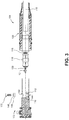
- each bus extension 110 may include a spade portion 112 (also referred to as "yoke spade portion 112") having a threaded bore 114 (shown in Fig. 2 ) extending therethrough.
- Each power cable assembly 104 may be prepared by connecting a power cable 115 to a crimp connector 116.
- Crimp connector 116 may include a substantially cylindrical assembly configured to receive a cable conductor 118 of power cable 115 therein.
- a portion of crimp connector 116 may be physically deformed (e.g., crimped) to fasten crimp connector 116 to cable conductor 118.
- Crimp connector 116 may include a forward spade portion 120 (shown in Fig. 3 ) (also referred to as “crimp connector spade portion 120") configured to be securely fastened to a spade portion 112 of bus extension 110 of central conductor 106.
- forward spade portions 120 of each crimp connector 116 may include an opening 121 therein (shown in Fig. 3 ) configured to align with threaded bore 114 in yoke spade portion 112.
- a threaded fastener 122 may be inserted through forward spade portion 120 and into threaded bore 114 of yoke spade portion 112 to secure crimp connector 116 to central conductor 106.
- each of the prepared power cable assemblies 104 may further include an adapter 124 disposed rearwardly relative to crimp connector 116.
- Adapter 124 may be affixed to power cable 115 and may provide a frictional engagement with a rearward portion of a respective cable receptacle 126-1 to 126-3 (collectively "cable receptacles 126," and generically “cable receptacle 126").
- adapter 124 may be formed of an insulative material, such as rubber, a thermoplastic, or epoxy.
- each tap 108 includes a cable receptacle interface 127 that includes a substantially cylindrical flange or cuff portion configured to frictionally engage cable receptacle 126.
- a substantially cylindrical flange or cuff portion configured to frictionally engage cable receptacle 126.
- an inside diameter of a forward end of cable receptacle 126 may be sized to frictionally engage the cuff portion of interface 127.
- Each cable receptacle 126 may be substantially cylindrical and may be configured to surround and protect an interface between power cable assembly 104 and bus extensions 110.
- cable receptacle 126 may provide a weather-resistant barrier for the interface between power cable assembly 104 and bus extensions 110.
- Yoke 102 may include a semi-conductive outer shield 128 formed from, for example, a peroxide-cured synthetic rubber, commonly referred to as EPDM (ethylenepropylene-dienemonomer). Within shield 128, yoke 102 may include an insulative inner housing 130, typically molded from an insulative rubber or epoxy material. Central conductor 106 may be enclosed within insulative inner housing 130.
- EPDM ethylenepropylene-dienemonomer
- each cable receptacle 126 may include an EPDM outer shield 132 and an insulative inner housing 133, typically molded from an insulative rubber or epoxy material. Cable receptacle 126 may further include a conductive or semi-conductive insert 134 having a longitudinal bore therethrough. Upon assembly, cable receptacle 126 surrounds the interface between power cable assembly 104 and bus extension 110. In one implementation, forward ends of insert 134 and outer shield 132 may be configured to frictionally engage a portion of yoke inner housing 130 at each tap 108 upon assembly of splicing connector 100, thereby ensuring the electrical integrity of splicing connector 100.
- tubular extensions 140-1 to 140-3 may extend from a respective bus extension 110-1 to 110-3.
- tubular extension 140 may be configured to fit within the inside diameter of insert 134 of cable receptacle 126 and over yoke spade portion 112 and crimp connector 116 without interference.
- tubular extension 140 may have different wall thickness depending on the particular size and available clearances at the interface of crimp connector 116 and insert 134.
- Tubular extension 140 may include a metallic material, such as aluminum, or a plastic material, such as reinforced fiberglass.
- tubular extension 140 may be made from the same material as central conductor 106.
- Tubular extension 140 may generally include a cylindrical shape or another tube-like cross-section (e.g., octagonal, hexagonal, etc.) to match the shape of bus extension 110.
- Tubular extension 140 may be secured to bus extension 110 by welding, by a threaded connection, or by another type of connection.
- tubular extension 140 supports cable receptacle 126 to prevent misalignment of power cable assembly 104 with yoke 102 and/or to prevent movement of power cable assembly 104 (e.g., rotation or bending relative to yoke 102) due to temporary high current.
- tubular extension 140 may include an access hole 142 and an exit hole 144. Tubular extension 140 may be affixed to bus extension 110 so that access hole 142 and exit hole 144 may align with bore 114 (e.g., to permit insertion of threaded fastener 120 into bore 114).
- Access hole 142 may be sized to permit fastener 122, a disc spring 146, and a washer 148 to pass through with sufficient clearance to enable assembly of threaded fastener 122 through forward spade portion 120 and yoke spade portion 112. More particularly, when assembled, access hole 142, exit hole 144, and bore114 may align with opening 121 to permit threaded fastener 122 to be inserted and engage corresponding threads in bore 114. Exit hole 144 may be provided to clear threaded fastener 122 after assembly (e.g., to allow fastener 122 to extend past the end of bore 114).
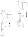
- FIGS. 4A, 4B , and 4C are top views of a portion of the three-way yoke 102 according to different implementation described herein.
- Figs. 4A and 4C illustrate a hook-shaped retention ring 150 on a distal end of tubular extension 140
- Fig. 4B illustrates a flared retention ring 152 on the distal end of tubular extension 140.
- hook-shaped retention ring 150 or flared retention ring 152 may be used in a latching arrangement with receptacle 126 to restrain outer shield 132 of receptacle 126 from sliding back from shield 128 of yoke 102.
- hook-shaped retention ring 150 may be formed, for example, by machining away a portion of an outer surface of tubular extension 140 such that a ring-shaped lip 154 extends beyond the machined surface 156.
- flared retention ring 152 maybe formed, for example, by turning out the circumference of the distal end of tubular extension 140.
- retention ring 152 may form an interference surface 158 that may be used, for example, in a latching arrangement described further herein.
- hook-shaped retention ring 150 may be formed by machining away a smaller portion (relative to that of Fig. 4A ) of the outer surface of tubular extension 140 such that a ring-shaped lip 154 extends beyond the machined surface 156 and a larger diameter outer surface 157 extends to the proximal end of tubular extension 140.
- Fig. 5 is a schematic cross-sectional diagram illustrating power cable assembly 104 according to another implementation described herein.
- cable receptacle 126 is slid back from crimp connector 116 (e.g., prior to connection of power cable assembly 104 and bus extension 110).
- insert 134 of cable receptacle 126 may include a latching ring 160.
- Latching ring 160 may extend radially along the inner circumference of insert 134.
- latching ring 160 may be an integrally molded piece with insert 134.
- latching ring 160 may be affixed to, or otherwise formed on, an inner surface of insert 134.
- Latching ring 160 may include a forward sloped surface 162 and a rear engagement surface 164.
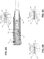
- Figs. 6A, 6B, and 6C are schematic, cross-sectional diagrams illustrating the interface between receptacle insert 134 with latching ring 160 and tubular extension 140.
- cable receptacle 126 is slid over crimp connector 116 and tubular extension 140 (e.g., after connection of power cable assembly 104 and bus extension 110).
- Figs. 6A and 6C show the interface between retention ring 150 and latching ring 160
- Fig. 6B shows the interface between retention ring 152 and latching ring 160.
- latching ring 160 may be positioned along cable receptacle 126/insert 134 to engage retention ring 150 or retention ring 152 when cable receptacle 126 is fully closed over crimp connector 116.
- Retention rings 150 or 152 and latching ring 160 may be generally configured to interlock to retain cable receptacle 126 in a position to maintain a weather-resistant barrier for the interface between power cable assembly 104 and bus extension 110.
- Latching ring 160, insert 134, and/or cable receptacle 126 may have elastic properties to both allow for sealing of the interface between power cable assembly 104 and yoke 102 and to permit latching ring 160 to be forced over retention ring 150 and/or retention ring 152.
- latching ring 160 may slide over retention ring 150.
- Forward sloped surface 162 may act as an inclined plane to translate axial forces applied to cable receptacle 126 and force latching ring over retention ring 150.
- retention ring 150 may include a corresponding slope to guide forward sloped surface 162 over retention ring 150.
- latching ring 160 may slide over retention ring 152.
- Forward sloped surface 162 may act as an inclined plane to translate axial forces applied to cable receptacle 126 and force latching ring over retention ring 152.
- latching ring 160 will pass over retention ring 152 so that rear engagement surface 164 will contact interference surface 158 if cable receptacle 126 is forced away from yoke 102.
- cable receptacle 126 is slid over tubular extension 140 (e.g., toward yoke 102) and latching ring 160 may slide over retention ring 150 similar to that described above with respect to Fig. 6A .
- latching ring 160 will pass over retention ring 150 so that rear engagement surface 164 will contact lip 154 if cable receptacle 126 is forced away from yoke 102.
- the larger diameter outer surface 157 may provide a smaller clearance between tubular extension 140 and insert 134 of receptacle 126.
- the interface of retention ring 150 and/or retention ring 152 and latching yoke 160 may removeably lock cable receptacle 126 in place.
- Elastic properties of latching ring 160, insert 134, and/or cable receptacle 126 may permit removal of cable receptacle 126 from tubular extension 140 using, for example, a removal tool.
- a yoke for a power cable connector may include a spade assembly that includes a bore therethrough and an electrical interface for a receptacle of a power cable.
- a tube-like structure may be affixed to the yoke and configured to encircle at least a portion of the spade assembly.
- the tube-like structure may include an entry hole through the tube-like structure to permit insertion of a fastener transversely through the tube-like structure and through the bore to securing the spade assembly to a portion of a second electrical component, such as a spade assembly of a power cable.
- the tube-like structure may have an outside diameter configured to engage an inside diameter of the receptacle and support the receptacle when the receptacle is connected to the electrical interface.
- the above-described power cable yoke with tubular extension provides an effective and repeatable means for preventing misalignment and/or relative movement of a yoke and an installed power cable assembly. Misalignment and/or movement may occur, for example, from bending forces caused by a high current momentary surge. This misalignment and/or movement may compromise the weather-resistant barrier provided by the cable receptacle. For example, water may reach the interface between cable receptacle and the taps of the yoke and eventually cause the connecting parts to electrically fail.
Landscapes
- Engineering & Computer Science (AREA)
- Manufacturing & Machinery (AREA)
- Details Of Connecting Devices For Male And Female Coupling (AREA)
- Connector Housings Or Holding Contact Members (AREA)
- Cable Accessories (AREA)
Claims (14)
- Connecteur, comprenant :un premier élément (110) ayant un premier alésage (114) traversant ;un second élément (116) ayant un second alésage (121) traversant configuré pour s'aligner avec le premier alésage dans le premier élément ;un élément de fixation (122) pour fixer le premier élément au second élément à travers le premier alésage et le second alésage ; etun réceptacle (126) ;le connecteur étant caractérisé en ce que :une extension tubulaire (140) est fixée, au niveau d'une extrémité proximale, au premier élément et configurée pour encercler au moins une partie du premier élément, une partie du second élément et l'élément de fixation, dans lequel l'extension tubulaire comprend un trou d'accès (142) pour permettre l'insertion de l'élément de fixation à travers le premier alésage et le second alésage ; etle réceptacle (126) étant configuré pour glisser sur au moins une partie du premier élément, une partie du second élément, l'élément de fixation et l'extension tubulaire pour former une barrière résistante aux intempéries pour le connecteur et dans lequel l'extension tubulaire est configurée pour maintenir le réceptacle et pour verrouiller le réceptacle en place lorsque le réceptacle est entièrement inséré au-dessus de l'extension tubulaire.
- Connecteur selon la revendication 1, dans lequel l'extension tubulaire comprend une extrémité distale avec une ouverture pour recevoir la partie du second élément.
- Connecteur selon la revendication 2, dans lequel l'extension tubulaire comprend un diamètre intérieur configuré pour recevoir sans interférence la partie du second élément.
- Connecteur selon la revendication 1, dans lequel l'extension tubulaire est fixée de façon rigide à une autre partie du premier élément.
- Connecteur selon la revendication 4, dans lequel l'extension tubulaire est soudée à l'autre partie du premier élément.
- Connecteur selon la revendication 4, dans lequel l'extension tubulaire et l'autre partie du premier élément sont reliées via une connexion filetée.
- Connecteur selon la revendication 1, dans lequel :l'extension tubulaire comprend en outre une bague de retenue (150, 152) sur un diamètre extérieur de l'extension tubulaire ;le réceptacle comprend en outre une bague de blocage (160) sur un diamètre intérieur du réceptacle ; etla bague de retenue et la bague de blocage sont configurées pour s'interverrouiller pour retenir le réceptacle en position en vue de maintenir la barrière résistante aux intempéries.
- Connecteur selon la revendication 7, dans lequel la bague de retenue est formée à partir d'une partie écartée au niveau de l'extrémité distale de l'extension tubulaire.
- Connecteur selon la revendication 7, dans lequel la bague de retenue est formée en usinant un diamètre extérieur de l'extension tubulaire.
- Connecteur selon la revendication 1, dans lequel l'extension tubulaire comprend un matériau en aluminium.
- Connecteur selon la revendication 1, dans lequel :le premier élément est un premier dispositif électrique et le second élément est un second dispositif électrique ; etl'élément tubulaire empêche la flexion du second élément par rapport au premier élément en cas de surtension de haute tension.
- Connecteur selon la revendication 11, dans lequel le premier élément comprend une première partie en forme de bêche (112) d'un collier de câble d'alimentation de haute tension et le second élément comprend une seconde partie en forme de bêche (120) d'un câble d'alimentation de haute tension.
- Connecteur électrique selon la revendication 1, dans lequel l'extension tubulaire comprend en outre :un trou de sortie (144), opposé au trou d'accès, pour permettre le passage de l'extension de l'élément de fixation à travers le premier alésage ou le second alésage.
- Procédé de connexion d'un premier composant électrique à un second composant électrique, comprenant :la mise à disposition d'un premier élément (110) ayant une première partie en forme de bêche (112) avec un premier alésage (114) traversant et une structure tubulaire (140) encerclant la première partie en forme de bêche, dans lequel la structure tubulaire comprend une bague de retenue (150, 152) disposée le long d'un diamètre extérieur de la structure tubulaire ;la mise à disposition d'un second élément (116) ayant une seconde partie en forme de bêche (120) avec un second alésage (121) traversant et un réceptacle (126) relié de façon coulissante au second élément, dans lequel le réceptacle comprend une bague de blocage (160) disposée sur un diamètre intérieur du réceptacle ;le positionnement de la seconde partie en forme de bêche à l'intérieur de la structure tubulaire et l'alignement du second alésage avec le premier alésage dans le premier élément ;l'insertion d'un élément de fixation (122) à travers un trou d'accès (142) dans la structure tubulaire jusque dans le premier alésage et le second alésage ; etle coulissement du réceptacle au-dessus de la structure tubulaire jusqu'à ce que la bague de blocage entre en prise avec la bague de retenue pour verrouiller le réceptacle en place et pour fournir une barrière résistante aux intempéries au-dessus de la structure tubulaire.
Applications Claiming Priority (2)
| Application Number | Priority Date | Filing Date | Title |
|---|---|---|---|
| US201261670828P | 2012-07-12 | 2012-07-12 | |
| US13/903,049 US8986034B2 (en) | 2012-07-12 | 2013-05-28 | Restraint and lock for electrical connector |
Publications (3)
| Publication Number | Publication Date |
|---|---|
| EP2685563A2 EP2685563A2 (fr) | 2014-01-15 |
| EP2685563A3 EP2685563A3 (fr) | 2015-02-18 |
| EP2685563B1 true EP2685563B1 (fr) | 2016-12-28 |
Family
ID=48771342
Family Applications (1)
| Application Number | Title | Priority Date | Filing Date |
|---|---|---|---|
| EP13176192.6A Active EP2685563B1 (fr) | 2012-07-12 | 2013-07-11 | Élément de retenue et de verrouillage pour connecteur électrique |
Country Status (5)
| Country | Link |
|---|---|
| US (1) | US8986034B2 (fr) |
| EP (1) | EP2685563B1 (fr) |
| CA (1) | CA2818427C (fr) |
| ES (1) | ES2616580T3 (fr) |
| MX (1) | MX2013008125A (fr) |
Cited By (1)
| Publication number | Priority date | Publication date | Assignee | Title |
|---|---|---|---|---|
| EP4391263A1 (fr) * | 2022-12-23 | 2024-06-26 | Nexans | Nouvelle conception de connecteur en t pour connexions haute tension robustes et polyvalents |
Families Citing this family (1)
| Publication number | Priority date | Publication date | Assignee | Title |
|---|---|---|---|---|
| US10419567B2 (en) * | 2017-03-21 | 2019-09-17 | Elite Silicon Technology Inc. | Client terminal of audio device redirection system and audio device redirection method |
Family Cites Families (26)
| Publication number | Priority date | Publication date | Assignee | Title |
|---|---|---|---|---|
| US3689866A (en) | 1970-09-11 | 1972-09-05 | William Kelly | Heavy duty cable connector |
| US5277605A (en) | 1992-09-10 | 1994-01-11 | Cooper Power Systems, Inc. | Electrical connector |
| US5433622A (en) | 1994-07-07 | 1995-07-18 | Galambos; Louis G. | High voltage connector |
| EP0767523A3 (fr) | 1995-10-02 | 1997-07-23 | Minnesota Mining & Mfg | Dispositif de recouvrement amélioré |
| US5685730A (en) | 1996-03-15 | 1997-11-11 | Litton Precision Products International, Inc. | Power connector set with secondary lock |
| GB9615747D0 (en) | 1996-07-26 | 1996-09-04 | Raychem Gmbh | Electric connection |
| JP3272263B2 (ja) | 1997-04-18 | 2002-04-08 | タイコエレクトロニクスアンプ株式会社 | 端子振れ防止機構を備えたコネクタ |
| US6332785B1 (en) | 1997-06-30 | 2001-12-25 | Cooper Industries, Inc. | High voltage electrical connector with access cavity and inserts for use therewith |
| JP3227138B2 (ja) | 1999-03-01 | 2001-11-12 | 日本圧着端子製造株式会社 | 高電圧用コネクタ |
| US6152770A (en) | 1999-03-26 | 2000-11-28 | Wang; Lien-Sheng | Water-proof socket adapter design |
| US6309231B1 (en) | 1999-09-02 | 2001-10-30 | Litton Precision Products International, Inc. | High current male and female power connector assembly |
| US6485326B1 (en) | 2000-10-19 | 2002-11-26 | France/Scott Fetzer Company | High-voltage connection enclosure and method |
| US6729903B1 (en) | 2002-12-04 | 2004-05-04 | Maytag Corporation | Quick connect/disconnect electrical connector having an extended insulating tab |
| US6884124B1 (en) | 2003-11-05 | 2005-04-26 | Richards Manufacturing Company | Barrier head bolt for use with disconnectable joints and methods of using the same |
| US7491075B2 (en) | 2005-07-28 | 2009-02-17 | Cooper Technologies Company | Electrical connector |
| US7695300B2 (en) | 2007-03-22 | 2010-04-13 | Eaton Corporation | Electrically insulated conductor connection assemblies and associated method |
| US7695333B2 (en) | 2007-12-13 | 2010-04-13 | Cooper Technologies Company | Single pole cable connector |
| US7530843B1 (en) | 2008-03-19 | 2009-05-12 | Yazaki North America, Inc. | Sealed electrical terminal |
| US7892047B2 (en) | 2008-04-30 | 2011-02-22 | Cooper Technologies Company | Single pole cable connector with tamper resistant locking mechanism |
| US7726998B2 (en) * | 2008-07-17 | 2010-06-01 | Thomas & Betts International, Inc. | Locking pin |
| US8172624B2 (en) | 2008-12-05 | 2012-05-08 | Hubbell Incorporated | Wiring device assembly with contact stabilizing structure |
| CA2680582C (fr) | 2009-09-16 | 2017-08-22 | Richards Manufacturing Company, A New Jersey Limited Partnership | Indicateur de retenue et d'appariement d'epissures |
| FR2953071B1 (fr) | 2009-11-23 | 2012-04-20 | Tyco Electronics France Sas | Boitier de connecteur electrique |
| US8616908B2 (en) * | 2010-03-03 | 2013-12-31 | Thomas & Betts International, Inc. | Electrical connector with a cap with a sacrificial conductor |
| CA2752903C (fr) | 2010-10-07 | 2015-07-14 | Thomas & Betts International, Inc. | Bride de serrage a came pour connecteur electrique |
| US8882548B2 (en) * | 2010-10-07 | 2014-11-11 | Thomas & Betts International Llc | Cam clamp for electrical connector |
-
2013
- 2013-05-28 US US13/903,049 patent/US8986034B2/en active Active
- 2013-06-14 CA CA2818427A patent/CA2818427C/fr not_active Expired - Fee Related
- 2013-07-11 EP EP13176192.6A patent/EP2685563B1/fr active Active
- 2013-07-11 ES ES13176192.6T patent/ES2616580T3/es active Active
- 2013-07-11 MX MX2013008125A patent/MX2013008125A/es active IP Right Grant
Non-Patent Citations (1)
| Title |
|---|
| None * |
Cited By (1)
| Publication number | Priority date | Publication date | Assignee | Title |
|---|---|---|---|---|
| EP4391263A1 (fr) * | 2022-12-23 | 2024-06-26 | Nexans | Nouvelle conception de connecteur en t pour connexions haute tension robustes et polyvalents |
Also Published As
| Publication number | Publication date |
|---|---|
| US20140017923A1 (en) | 2014-01-16 |
| CA2818427C (fr) | 2016-07-05 |
| US8986034B2 (en) | 2015-03-24 |
| MX2013008125A (es) | 2014-01-17 |
| EP2685563A2 (fr) | 2014-01-15 |
| CA2818427A1 (fr) | 2014-01-12 |
| ES2616580T3 (es) | 2017-06-13 |
| EP2685563A3 (fr) | 2015-02-18 |
Similar Documents
| Publication | Publication Date | Title |
|---|---|---|
| EP3021424B1 (fr) | Ensemble de connecteur électrique comprenant une liaison de mise à la terre et procédé correspondant de connexion | |
| EP2688153B1 (fr) | Connecteur électrique comportant un mécanisme de mise à la terre | |
| US8172596B2 (en) | Electrical connector with sacrificial appendage | |
| EP3032654B1 (fr) | Ensemble connecteur électrique et agencement de connexion | |
| EP2854240B1 (fr) | Point de mise à la terre permanent pour épisser des connecteurs | |
| EP3062399B1 (fr) | Chemise en plusieurs parties pour connecteurs séparables | |
| US8616908B2 (en) | Electrical connector with a cap with a sacrificial conductor | |
| EP2685563B1 (fr) | Élément de retenue et de verrouillage pour connecteur électrique | |
| US9124015B2 (en) | Electrical connector with sacrificial appendage and a grounding element | |
| EP3048670A1 (fr) | Connecteur électrique comportant un mécanisme de mise à la terre | |
| CA2846946C (fr) | Connecteur electrique a appendice jetable | |
| CA2733112C (fr) | Connecteur electrique a appendice jetable | |
| HK1223456B (en) | Electrical connector assembly comprising a grounding link and corresponding method of connection | |
| CA2776706C (fr) | Connecteur electrique avec appendice sacrificiel | |
| HK1226870B (en) | Multi-piece jacket for separable connectors | |
| HK1226870A1 (en) | Multi-piece jacket for separable connectors |
Legal Events
| Date | Code | Title | Description |
|---|---|---|---|
| PUAI | Public reference made under article 153(3) epc to a published international application that has entered the european phase |
Free format text: ORIGINAL CODE: 0009012 |
|
| AK | Designated contracting states |
Kind code of ref document: A2 Designated state(s): AL AT BE BG CH CY CZ DE DK EE ES FI FR GB GR HR HU IE IS IT LI LT LU LV MC MK MT NL NO PL PT RO RS SE SI SK SM TR |
|
| AX | Request for extension of the european patent |
Extension state: BA ME |
|
| PUAL | Search report despatched |
Free format text: ORIGINAL CODE: 0009013 |
|
| AK | Designated contracting states |
Kind code of ref document: A3 Designated state(s): AL AT BE BG CH CY CZ DE DK EE ES FI FR GB GR HR HU IE IS IT LI LT LU LV MC MK MT NL NO PL PT RO RS SE SI SK SM TR |
|
| AX | Request for extension of the european patent |
Extension state: BA ME |
|
| RIC1 | Information provided on ipc code assigned before grant |
Ipc: H01R 4/34 20060101ALI20150114BHEP Ipc: H01R 4/56 20060101ALI20150114BHEP Ipc: H01R 31/02 20060101ALI20150114BHEP Ipc: H01R 43/00 20060101ALI20150114BHEP Ipc: H01R 43/26 20060101ALN20150114BHEP Ipc: H01R 4/70 20060101AFI20150114BHEP |
|
| 17P | Request for examination filed |
Effective date: 20150818 |
|
| RBV | Designated contracting states (corrected) |
Designated state(s): AL AT BE BG CH CY CZ DE DK EE ES FI FR GB GR HR HU IE IS IT LI LT LU LV MC MK MT NL NO PL PT RO RS SE SI SK SM TR |
|
| GRAP | Despatch of communication of intention to grant a patent |
Free format text: ORIGINAL CODE: EPIDOSNIGR1 |
|
| RIC1 | Information provided on ipc code assigned before grant |
Ipc: H01R 4/56 20060101ALI20160616BHEP Ipc: H01R 43/26 20060101ALN20160616BHEP Ipc: H01R 4/70 20060101AFI20160616BHEP Ipc: H01R 31/02 20060101ALI20160616BHEP Ipc: H01R 43/00 20060101ALI20160616BHEP Ipc: H01R 4/34 20060101ALI20160616BHEP |
|
| INTG | Intention to grant announced |
Effective date: 20160706 |
|
| GRAS | Grant fee paid |
Free format text: ORIGINAL CODE: EPIDOSNIGR3 |
|
| GRAA | (expected) grant |
Free format text: ORIGINAL CODE: 0009210 |
|
| RAP1 | Party data changed (applicant data changed or rights of an application transferred) |
Owner name: THOMAS & BETTS INTERNATIONAL LLC |
|
| AK | Designated contracting states |
Kind code of ref document: B1 Designated state(s): AL AT BE BG CH CY CZ DE DK EE ES FI FR GB GR HR HU IE IS IT LI LT LU LV MC MK MT NL NO PL PT RO RS SE SI SK SM TR |
|
| REG | Reference to a national code |
Ref country code: GB Ref legal event code: FG4D |
|
| REG | Reference to a national code |
Ref country code: CH Ref legal event code: EP |
|
| REG | Reference to a national code |
Ref country code: AT Ref legal event code: REF Ref document number: 858003 Country of ref document: AT Kind code of ref document: T Effective date: 20170115 |
|
| REG | Reference to a national code |
Ref country code: IE Ref legal event code: FG4D |
|
| REG | Reference to a national code |
Ref country code: DE Ref legal event code: R096 Ref document number: 602013015812 Country of ref document: DE |
|
| REG | Reference to a national code |
Ref country code: SE Ref legal event code: TRGR |
|
| PG25 | Lapsed in a contracting state [announced via postgrant information from national office to epo] |
Ref country code: LV Free format text: LAPSE BECAUSE OF FAILURE TO SUBMIT A TRANSLATION OF THE DESCRIPTION OR TO PAY THE FEE WITHIN THE PRESCRIBED TIME-LIMIT Effective date: 20161228 |
|
| REG | Reference to a national code |
Ref country code: NL Ref legal event code: FP |
|
| REG | Reference to a national code |
Ref country code: LT Ref legal event code: MG4D |
|
| PG25 | Lapsed in a contracting state [announced via postgrant information from national office to epo] |
Ref country code: GR Free format text: LAPSE BECAUSE OF FAILURE TO SUBMIT A TRANSLATION OF THE DESCRIPTION OR TO PAY THE FEE WITHIN THE PRESCRIBED TIME-LIMIT Effective date: 20170329 Ref country code: LT Free format text: LAPSE BECAUSE OF FAILURE TO SUBMIT A TRANSLATION OF THE DESCRIPTION OR TO PAY THE FEE WITHIN THE PRESCRIBED TIME-LIMIT Effective date: 20161228 Ref country code: NO Free format text: LAPSE BECAUSE OF FAILURE TO SUBMIT A TRANSLATION OF THE DESCRIPTION OR TO PAY THE FEE WITHIN THE PRESCRIBED TIME-LIMIT Effective date: 20170328 |
|
| REG | Reference to a national code |
Ref country code: AT Ref legal event code: MK05 Ref document number: 858003 Country of ref document: AT Kind code of ref document: T Effective date: 20161228 |
|
| PG25 | Lapsed in a contracting state [announced via postgrant information from national office to epo] |
Ref country code: FI Free format text: LAPSE BECAUSE OF FAILURE TO SUBMIT A TRANSLATION OF THE DESCRIPTION OR TO PAY THE FEE WITHIN THE PRESCRIBED TIME-LIMIT Effective date: 20161228 Ref country code: HR Free format text: LAPSE BECAUSE OF FAILURE TO SUBMIT A TRANSLATION OF THE DESCRIPTION OR TO PAY THE FEE WITHIN THE PRESCRIBED TIME-LIMIT Effective date: 20161228 Ref country code: RS Free format text: LAPSE BECAUSE OF FAILURE TO SUBMIT A TRANSLATION OF THE DESCRIPTION OR TO PAY THE FEE WITHIN THE PRESCRIBED TIME-LIMIT Effective date: 20161228 |
|
| REG | Reference to a national code |
Ref country code: FR Ref legal event code: PLFP Year of fee payment: 5 Ref country code: ES Ref legal event code: FG2A Ref document number: 2616580 Country of ref document: ES Kind code of ref document: T3 Effective date: 20170613 |
|
| PG25 | Lapsed in a contracting state [announced via postgrant information from national office to epo] |
Ref country code: RO Free format text: LAPSE BECAUSE OF FAILURE TO SUBMIT A TRANSLATION OF THE DESCRIPTION OR TO PAY THE FEE WITHIN THE PRESCRIBED TIME-LIMIT Effective date: 20161228 Ref country code: EE Free format text: LAPSE BECAUSE OF FAILURE TO SUBMIT A TRANSLATION OF THE DESCRIPTION OR TO PAY THE FEE WITHIN THE PRESCRIBED TIME-LIMIT Effective date: 20161228 Ref country code: IS Free format text: LAPSE BECAUSE OF FAILURE TO SUBMIT A TRANSLATION OF THE DESCRIPTION OR TO PAY THE FEE WITHIN THE PRESCRIBED TIME-LIMIT Effective date: 20170428 Ref country code: SK Free format text: LAPSE BECAUSE OF FAILURE TO SUBMIT A TRANSLATION OF THE DESCRIPTION OR TO PAY THE FEE WITHIN THE PRESCRIBED TIME-LIMIT Effective date: 20161228 Ref country code: CZ Free format text: LAPSE BECAUSE OF FAILURE TO SUBMIT A TRANSLATION OF THE DESCRIPTION OR TO PAY THE FEE WITHIN THE PRESCRIBED TIME-LIMIT Effective date: 20161228 |
|
| PG25 | Lapsed in a contracting state [announced via postgrant information from national office to epo] |
Ref country code: PT Free format text: LAPSE BECAUSE OF FAILURE TO SUBMIT A TRANSLATION OF THE DESCRIPTION OR TO PAY THE FEE WITHIN THE PRESCRIBED TIME-LIMIT Effective date: 20170428 Ref country code: SM Free format text: LAPSE BECAUSE OF FAILURE TO SUBMIT A TRANSLATION OF THE DESCRIPTION OR TO PAY THE FEE WITHIN THE PRESCRIBED TIME-LIMIT Effective date: 20161228 Ref country code: AT Free format text: LAPSE BECAUSE OF FAILURE TO SUBMIT A TRANSLATION OF THE DESCRIPTION OR TO PAY THE FEE WITHIN THE PRESCRIBED TIME-LIMIT Effective date: 20161228 Ref country code: BG Free format text: LAPSE BECAUSE OF FAILURE TO SUBMIT A TRANSLATION OF THE DESCRIPTION OR TO PAY THE FEE WITHIN THE PRESCRIBED TIME-LIMIT Effective date: 20170328 Ref country code: PL Free format text: LAPSE BECAUSE OF FAILURE TO SUBMIT A TRANSLATION OF THE DESCRIPTION OR TO PAY THE FEE WITHIN THE PRESCRIBED TIME-LIMIT Effective date: 20161228 |
|
| REG | Reference to a national code |
Ref country code: DE Ref legal event code: R097 Ref document number: 602013015812 Country of ref document: DE |
|
| PLBE | No opposition filed within time limit |
Free format text: ORIGINAL CODE: 0009261 |
|
| STAA | Information on the status of an ep patent application or granted ep patent |
Free format text: STATUS: NO OPPOSITION FILED WITHIN TIME LIMIT |
|
| PG25 | Lapsed in a contracting state [announced via postgrant information from national office to epo] |
Ref country code: DK Free format text: LAPSE BECAUSE OF FAILURE TO SUBMIT A TRANSLATION OF THE DESCRIPTION OR TO PAY THE FEE WITHIN THE PRESCRIBED TIME-LIMIT Effective date: 20161228 |
|
| 26N | No opposition filed |
Effective date: 20170929 |
|
| PG25 | Lapsed in a contracting state [announced via postgrant information from national office to epo] |
Ref country code: SI Free format text: LAPSE BECAUSE OF FAILURE TO SUBMIT A TRANSLATION OF THE DESCRIPTION OR TO PAY THE FEE WITHIN THE PRESCRIBED TIME-LIMIT Effective date: 20161228 |
|
| REG | Reference to a national code |
Ref country code: CH Ref legal event code: PL |
|
| PG25 | Lapsed in a contracting state [announced via postgrant information from national office to epo] |
Ref country code: CH Free format text: LAPSE BECAUSE OF NON-PAYMENT OF DUE FEES Effective date: 20170731 Ref country code: LI Free format text: LAPSE BECAUSE OF NON-PAYMENT OF DUE FEES Effective date: 20170731 |
|
| REG | Reference to a national code |
Ref country code: FR Ref legal event code: PLFP Year of fee payment: 6 |
|
| PG25 | Lapsed in a contracting state [announced via postgrant information from national office to epo] |
Ref country code: LU Free format text: LAPSE BECAUSE OF NON-PAYMENT OF DUE FEES Effective date: 20170711 |
|
| PG25 | Lapsed in a contracting state [announced via postgrant information from national office to epo] |
Ref country code: MT Free format text: LAPSE BECAUSE OF NON-PAYMENT OF DUE FEES Effective date: 20170711 |
|
| PG25 | Lapsed in a contracting state [announced via postgrant information from national office to epo] |
Ref country code: HU Free format text: LAPSE BECAUSE OF FAILURE TO SUBMIT A TRANSLATION OF THE DESCRIPTION OR TO PAY THE FEE WITHIN THE PRESCRIBED TIME-LIMIT; INVALID AB INITIO Effective date: 20130711 Ref country code: MC Free format text: LAPSE BECAUSE OF FAILURE TO SUBMIT A TRANSLATION OF THE DESCRIPTION OR TO PAY THE FEE WITHIN THE PRESCRIBED TIME-LIMIT Effective date: 20161228 |
|
| PG25 | Lapsed in a contracting state [announced via postgrant information from national office to epo] |
Ref country code: CY Free format text: LAPSE BECAUSE OF NON-PAYMENT OF DUE FEES Effective date: 20161228 |
|
| PG25 | Lapsed in a contracting state [announced via postgrant information from national office to epo] |
Ref country code: MK Free format text: LAPSE BECAUSE OF FAILURE TO SUBMIT A TRANSLATION OF THE DESCRIPTION OR TO PAY THE FEE WITHIN THE PRESCRIBED TIME-LIMIT Effective date: 20161228 |
|
| PG25 | Lapsed in a contracting state [announced via postgrant information from national office to epo] |
Ref country code: TR Free format text: LAPSE BECAUSE OF FAILURE TO SUBMIT A TRANSLATION OF THE DESCRIPTION OR TO PAY THE FEE WITHIN THE PRESCRIBED TIME-LIMIT Effective date: 20161228 |
|
| PG25 | Lapsed in a contracting state [announced via postgrant information from national office to epo] |
Ref country code: AL Free format text: LAPSE BECAUSE OF FAILURE TO SUBMIT A TRANSLATION OF THE DESCRIPTION OR TO PAY THE FEE WITHIN THE PRESCRIBED TIME-LIMIT Effective date: 20161228 |
|
| PGFP | Annual fee paid to national office [announced via postgrant information from national office to epo] |
Ref country code: NL Payment date: 20250721 Year of fee payment: 13 |
|
| PGFP | Annual fee paid to national office [announced via postgrant information from national office to epo] |
Ref country code: ES Payment date: 20250826 Year of fee payment: 13 |
|
| PGFP | Annual fee paid to national office [announced via postgrant information from national office to epo] |
Ref country code: DE Payment date: 20250722 Year of fee payment: 13 |
|
| PGFP | Annual fee paid to national office [announced via postgrant information from national office to epo] |
Ref country code: IT Payment date: 20250724 Year of fee payment: 13 |
|
| PGFP | Annual fee paid to national office [announced via postgrant information from national office to epo] |
Ref country code: BE Payment date: 20250721 Year of fee payment: 13 Ref country code: GB Payment date: 20250722 Year of fee payment: 13 |
|
| PGFP | Annual fee paid to national office [announced via postgrant information from national office to epo] |
Ref country code: FR Payment date: 20250725 Year of fee payment: 13 |
|
| PGFP | Annual fee paid to national office [announced via postgrant information from national office to epo] |
Ref country code: SE Payment date: 20250722 Year of fee payment: 13 |
|
| PGFP | Annual fee paid to national office [announced via postgrant information from national office to epo] |
Ref country code: IE Payment date: 20250723 Year of fee payment: 13 |