EP2685579A2 - Procédé de détection d'état de déconnexion de câble d'alimentation dans un système d'inverseur - Google Patents
Procédé de détection d'état de déconnexion de câble d'alimentation dans un système d'inverseur Download PDFInfo
- Publication number
- EP2685579A2 EP2685579A2 EP13165936.9A EP13165936A EP2685579A2 EP 2685579 A2 EP2685579 A2 EP 2685579A2 EP 13165936 A EP13165936 A EP 13165936A EP 2685579 A2 EP2685579 A2 EP 2685579A2
- Authority
- EP
- European Patent Office
- Prior art keywords
- power cable
- motor
- detecting
- inverter
- power
- Prior art date
- Legal status (The legal status is an assumption and is not a legal conclusion. Google has not performed a legal analysis and makes no representation as to the accuracy of the status listed.)
- Granted
Links
Images


Classifications
-
- G—PHYSICS
- G01—MEASURING; TESTING
- G01R—MEASURING ELECTRIC VARIABLES; MEASURING MAGNETIC VARIABLES
- G01R31/00—Arrangements for testing electric properties; Arrangements for locating electric faults; Arrangements for electrical testing characterised by what is being tested not provided for elsewhere
- G01R31/50—Testing of electric apparatus, lines, cables or components for short-circuits, continuity, leakage current or incorrect line connections
- G01R31/58—Testing of lines, cables or conductors
-
- G—PHYSICS
- G01—MEASURING; TESTING
- G01R—MEASURING ELECTRIC VARIABLES; MEASURING MAGNETIC VARIABLES
- G01R19/00—Arrangements for measuring currents or voltages or for indicating presence or sign thereof
- G01R19/10—Measuring sum, difference or ratio
-
- G—PHYSICS
- G01—MEASURING; TESTING
- G01R—MEASURING ELECTRIC VARIABLES; MEASURING MAGNETIC VARIABLES
- G01R31/00—Arrangements for testing electric properties; Arrangements for locating electric faults; Arrangements for electrical testing characterised by what is being tested not provided for elsewhere
- G01R31/08—Locating faults in cables, transmission lines, or networks
-
- G—PHYSICS
- G01—MEASURING; TESTING
- G01R—MEASURING ELECTRIC VARIABLES; MEASURING MAGNETIC VARIABLES
- G01R31/00—Arrangements for testing electric properties; Arrangements for locating electric faults; Arrangements for electrical testing characterised by what is being tested not provided for elsewhere
- G01R31/40—Testing power supplies
- G01R31/42—AC power supplies
-
- H—ELECTRICITY
- H02—GENERATION; CONVERSION OR DISTRIBUTION OF ELECTRIC POWER
- H02H—EMERGENCY PROTECTIVE CIRCUIT ARRANGEMENTS
- H02H5/00—Emergency protective circuit arrangements for automatic disconnection directly responsive to an undesired change from normal non-electric working conditions with or without subsequent reconnection
- H02H5/10—Emergency protective circuit arrangements for automatic disconnection directly responsive to an undesired change from normal non-electric working conditions with or without subsequent reconnection responsive to mechanical injury, e.g. rupture of line, breakage of earth connection
-
- H—ELECTRICITY
- H02—GENERATION; CONVERSION OR DISTRIBUTION OF ELECTRIC POWER
- H02H—EMERGENCY PROTECTIVE CIRCUIT ARRANGEMENTS
- H02H7/00—Emergency protective circuit arrangements specially adapted for specific types of electric machines or apparatus or for sectionalised protection of cable or line systems, and effecting automatic switching in the event of an undesired change from normal working conditions
- H02H7/10—Emergency protective circuit arrangements specially adapted for specific types of electric machines or apparatus or for sectionalised protection of cable or line systems, and effecting automatic switching in the event of an undesired change from normal working conditions for converters; for rectifiers
- H02H7/12—Emergency protective circuit arrangements specially adapted for specific types of electric machines or apparatus or for sectionalised protection of cable or line systems, and effecting automatic switching in the event of an undesired change from normal working conditions for converters; for rectifiers for static converters or rectifiers
- H02H7/122—Emergency protective circuit arrangements specially adapted for specific types of electric machines or apparatus or for sectionalised protection of cable or line systems, and effecting automatic switching in the event of an undesired change from normal working conditions for converters; for rectifiers for static converters or rectifiers for inverters, i.e. DC/AC converters
-
- H—ELECTRICITY
- H02—GENERATION; CONVERSION OR DISTRIBUTION OF ELECTRIC POWER
- H02P—CONTROL OR REGULATION OF ELECTRIC MOTORS, ELECTRIC GENERATORS OR DYNAMO-ELECTRIC CONVERTERS; CONTROLLING TRANSFORMERS, REACTORS OR CHOKE COILS
- H02P3/00—Arrangements for stopping or slowing electric motors, generators, or dynamo-electric converters
- H02P3/02—Details of stopping control
-
- G—PHYSICS
- G01—MEASURING; TESTING
- G01R—MEASURING ELECTRIC VARIABLES; MEASURING MAGNETIC VARIABLES
- G01R31/00—Arrangements for testing electric properties; Arrangements for locating electric faults; Arrangements for electrical testing characterised by what is being tested not provided for elsewhere
- G01R31/50—Testing of electric apparatus, lines, cables or components for short-circuits, continuity, leakage current or incorrect line connections
- G01R31/54—Testing for continuity
-
- H—ELECTRICITY
- H02—GENERATION; CONVERSION OR DISTRIBUTION OF ELECTRIC POWER
- H02J—ELECTRIC POWER NETWORKS; CIRCUIT ARRANGEMENTS OR SYSTEMS FOR SUPPLYING OR DISTRIBUTING ELECTRIC POWER; SYSTEMS FOR STORING ELECTRIC ENERGY
- H02J7/00—Circuit arrangements for charging or discharging batteries or for supplying loads from batteries
- H02J7/60—Circuit arrangements for charging or discharging batteries or for supplying loads from batteries including safety or protection arrangements
- H02J7/685—Circuit arrangements for charging or discharging batteries or for supplying loads from batteries including safety or protection arrangements using connection detecting circuits
Definitions
- the embodiment relates to an inverter.
- the embodiment relates to a method of detecting a non-connection state of a high-voltage cable constituting an inverter.
- An inverter system serving as a motor controller employed in an eco-friendly vehicle is an electric/electronic substrate assembly (ESA) to convert high-voltage DC power into AC power or DC power for the purpose of controlling a motor.
- ESA electric/electronic substrate assembly
- the inverter system is a main component constituting an electric motor of a vehicle.
- the above-described eco-friendly vehicle employs a permanent magnet motor as a driving unit.
- the motor applied to the eco-friendly vehicle while serving as the driving unit is driven by phase current transferred from the inverter, which converts DC voltage into 3-phase voltage, through the first high-voltage power cable according to a pulse width modulation (PWM) signal of a controller.
- PWM pulse width modulation
- the inverter converts DC-link voltage, which is transferred through the second high-voltage power cable according to the switching operation of a main relay, into 3-phase voltage.
- FIG. 1 is a view showing a device of detecting the disconnection state of a power cable in an inverter system according to the related art.
- a device of detecting the disconnection state of the power cable includes a power cable 10 and a disconnection detecting unit 20 connected with the power cable 10 to transmit a signal based on the disconnection state of the power cable 10 to the controller.
- the disconnection detecting unit 20 is connected to the power cable 10 to transmit a digital signal based on the connection state of the power cable 10 to the controller.
- a disconnection detecting unit for checking the disconnection state of the power cable 10 is installed on the power cable 10 in the form of a hardware separately provided from the power able 10, and the disconnection state of the power cable 10 is checked in real time by using a digital signal output from the disconnection detecting unit.
- the disconnection detecting unit for the power cable 10 detects the disconnection state of the power cable 10 in the form of a hardware, the above disconnection detection unit has limitations in terms of space as well as a price.
- the above disconnection detecting unit of the power cable 10 may be erroneously operated due to external causes.
- the embodiment provides a method of detecting a disconnection state of a power cable in an inverter system, capable of detecting the disconnection state (non-connection state) of the power cable through software implementation without additional hardware equipment.
- the embodiment provides a method of detecting the disconnection state of a power cable, capable of verifying the normal operating state of hardware equipment in a system having the hardware equipment that can detect the disconnection state of the power cable.
- a method of detecting a disconnection state of a power cable in an inverter system includes detecting a disconnection state of a first power cable by using a difference value between a battery voltage and a DC-link voltage, detecting a disconnection state of a second power cable by using a driving speed, a phase current instruction value, and an actual phase current value of a motor, and stopping driving of the motor if one of the first and second power cables is detected as being disconnected.
- the detecting of the disconnection state of the first power cable includes detecting the battery voltage, detecting the DC-link voltage, calculating the difference value between the detected battery voltage and the detected DC-link voltage, comparing the calculated difference value with a preset reference value, detecting the first power cable as being disconnected if the difference value is greater than the reference value, and detecting the first power cable as being normally connected if the difference value is less than the preset reference value.
- the first power cable is a DC-link power cable to supply DC power, which is charged in a battery, to an inverter.
- the method further includes determining a state of a main relay to control the DC power supplied to the inverter.
- the detecting of the disconnection state of the first power cable is performed when the state of the main relay is determined as an on-state.
- the stopping of the driving of the motor includes changing the state of the main relay to an off-state, and forcibly-discharging a capacitor included in the inverter.
- the forcibly-discharging of the capacitor included in the inverter includes setting a q-axis current serving as a torque component current to 0, and applying a d-axis current serving as a magnetic flux component current in the motor.
- the detecting of the disconnection state of the second power cable includes checking a driving speed of the motor, determining if the checked driving speed of the motor exceeds a reference speed, determining if a phase current instruction value to drive the motor is greater than a first reference value if the driving speed of the motor exceeds the reference speed, determining if an actual phase current applied to the motor is less than a second reference value if the phase current instruction value is greater than the first reference value, and detecting the second power cable as being disconnected if the actual phase current is less than the second reference value.
- the actual phase current is a current flowing through a 3-phase power cable to transfer a 3-phase AC power converted through an inverter to the motor.
- the stopping of the driving of the motor includes determining the 3-phase power cable as being disconnected if the actual phase current is less than the second reference value, and stopping the driving of the motor as the 3-phase power cable is disconnected.
- the method further includes determining the 3-phase power cable as being normally connected if the actual phase current is greater than the second reference value such that a driving power is continuously supplied to the motor.
- the stopping of the driving of the motor includes setting a q-axis current serving as a torque component current to 0, and applying a d-axis current serving as a magnetic flux component current in the motor such that a capacitor included in the inverter is forcibly discharged.
- the non-connection state of the power cable can be diagnosed through software implementation instead of a scheme of detecting the non-connection state of the power cable by installing hardware equipment on a power cable, which has been mainly used according to the related art, advantages can be made in terms of cost, and an erroneous operation, which may occur due to external causes, can be previously prevented.
- FIG. 1 is a view showing a device of detecting the disconnection state of a power cable in an inverter system according to the related art.
- FIG. 2 is a circuit diagram showing the structure of an inverter system according to the embodiment.
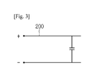
- FIG. 3 is a circuit diagram showing the first power cable according to the embodiment.
- FIG. 4 is a circuit diagram showing the second power cable according to the embodiment.
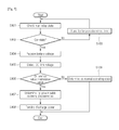
- FIG. 5 is a flowchart showing the method of detecting the disconnection state of the first power cable according to the embodiment.
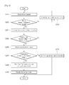
- FIG. 6 is a flowchart showing the method of detecting the disconnection state of the second power cable step by step according to the embodiment.
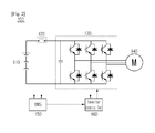
- FIG. 2 is a circuit diagram showing the structure of an inverter system 100 according to the embodiment.
- the inverter system 100 includes a battery 110, a main relay 120, an inverter 130, a motor 140, a battery management system (BMS) and an inverter controller 160.
- BMS battery management system
- the battery 110 supplies driving voltage to an electric vehicle (not shown).
- the battery 110 supplies DC power to a capacitor C provided in the inverter 130 included in the inverter system 100.
- the battery 110 is a high-voltage battery, and may include a plurality of unit cells.
- the unit cells may be managed by the BMS 150 in order to maintain predetermined voltage.
- the battery 110 may discharge predetermined voltage under the control of the BMS 150.
- the BMS 150 detects the voltage of the battery 110 and transmits the detected voltage to the inverter controller 160.
- the inverter controller 160 may supply to DC voltage, which is stored in capacitors provided in the electric vehicle, to the battery 110.
- the inverter controller 160 may supply the DC voltage, which is stored in the battery 110, to the capacitors of the electric vehicle.
- the battery 110 includes a rechargeable battery which may transit from a charging state to a discharging state according to the operating state thereof.
- the main relay 120 is connected to a predetermined power line connected to the battery 100 to control the DC voltage output through the battery 110.
- the main relay may include a first main relay connected to a positive terminal to control the DC voltage and a second main relay connected to a negative terminal to control the DC voltage.
- the inverter 130 receives DC voltage from the battery 110 according to the switching state of the main relay 120.
- the inverter 130 converts the DC voltage received therein from the battery 110 into AC voltage to be supplied to the motor 140.
- the AC voltage converted by the inverter 130 is preferably a 3-phase AC voltage.
- the inverter 130 includes an insulated gate bipolar transistor (IGBT) to perform a PWM (pulse width modulation) switching operation according to the control signal applied from the inverter controller 160, which is described later, thereby phase-transforming the voltage supplied from the battery 110 to drive the motor 140.
- IGBT insulated gate bipolar transistor
- the motor 140 includes a stator (not shown), which is in a stationary state without rotation, and a rotor (not shown) rotating.
- the motor 140 receives AC voltage that is supplied through the inverter 130.
- the motor 140 may include a 3-phase motor.
- voltage variable/frequency variable AC power is applied to a coil of a stator in each phase, the rotation speed of a rotor varies depending on the applied frequency.
- the motor 140 may include various types of an induction motor, a blushless DC (BLDC) motor, and a reluctance motor.
- BLDC blushless DC
- the motor 140 may be provided at one side thereof with a driving gear (not shown).
- the driving gear converts the rotational energy of the motor 140 according to a gear ratio.
- the rotational energy of the driving gear is transferred to a front wheel and/or a rear wheel so that the electric vehicle moves.
- the electric vehicle may further include an electronic controller to control whole electronic devices of the electric vehicle.
- the electronic controller (not shown) controls the operation and the displaying of each device.
- the electronic controller (not shown) may control the BMS 150.
- the electronic controller may generate a driving instruction value according to various operation modes (driving mode, rearward mode, neutral mode, and parking mode) based on detection signals transferred from an inclination angle detector (not shown) to detect the inclination angle of the electric vehicle, a speed detector (not shown) to detect the speed of the electric vehicle, a brake detector (not shown) according to the operation of a brake pedal, or an acceleration detector according to the operation of an acceleration pedal.
- the driving instruction value may include a torque instruction value or a speed instruction value.
- the electric vehicle may include a pure electric vehicle employing a battery and a motor, and a hybrid electric vehicle employing a battery and a motor together with an engine.
- the hybrid electric vehicle may include a switching unit to select at least one of the battery and the engine, and a transmission. Meanwhile, the hybrid electric vehicle is classified into a series hybrid electric vehicle, which converts mechanical energy output from an engine into electrical energy to drive the motor, and a parallel hybrid electric vehicle which uses both of the mechanical energy output from the engine and the electrical energy output from the battery.
- the BMS 150 allows the unit cells to maintain predetermined voltage.
- the BMS 150 discharges the voltage charged in the battery 110 to the inverter 130 through the main relay 120.
- the inverter controller 160 controls the operation of the inverter 130.
- the inverter controller 160 calculates a driving value used to drive the motor 140 by using current (3-phase current) supplied to the motor 140, and generates a switching signal (PWM signal) used to control the inverter 130 based on the calculated driving value.
- PWM signal a switching signal
- the inverter 130 is selectively turned on or turned off according to the switching signal generated through the inverter controller 160 to convert the DC power into AC power.
- the inverter controller 160 controls power supplied to the motor 140 by determining the state of a power cable through which the DC power or the AC power is supplied.
- the power cable includes a first power cable through which the DC power is supplied, and a second power cable through which the AC power is supplied.
- FIG. 3 is a circuit diagram showing the first power cable according to the embodiment
- FIG. 4 is a circuit diagram showing the second power cable according to the embodiment.
- the inverter system 100 includes a first power cable 200 used to receive DC power (DC-link voltage) from the battery 110 and supply the DC power to the inverter 130.
- DC power DC-link voltage
- the first power cable 200 are connected to positive (+) and negative (-) terminals of the battery 110, respectively, so that the DC power supplied through the battery 110 is supplied to the inverter 130.
- the inverter 130 does not receive normal DC power. Accordingly, problems may occur when driving the motor 140.
- the inverter controller 160 detects a disconnection state of the first power cable 200. If the first power cable 200 is detected as being separated, the inverter controller 160 cuts off power to be supplied to the inverter 130 and the motor 140
- a method of detecting the disconnection state of the first power cable 200 to cut off power will be described in more detail below.
- the inverter system 100 includes a second power cable 300 used to supply AC power converted through the inverter 130 to the motor 140.
- the inverter 130 supplies 3-phase AC power converted through the second power cable 300 (i.e., 3-phase cable) to the motor 140.
- the second power cable 300 may be divided into three individual cables. Alternately, three cables may be provided in one cable.
- the inverter controller 160 detects the disconnection state of the second power cable 300. If the second power cable 300 is detected as being disconnected, the inverter controller 160 cuts off power to be supplied to the motor 140.
- FIG. 5 is a flowchart showing the method of detecting the separation state of the first power cable 200 according to the embodiment.
- the BMS 150 detects the state of the main relay 120 (step S101).
- the BMS 150 determines whether the electric vehicle is currently driven so that the DC power stored in the battery 110 is supplied to the inverter 130, or the driving of the electric vehicle is stopped, so that the DC power is not supplied to the inverter 130.
- the BMS 150 determines if the main relay 120 is turned on (step S102).
- the BMS 150 checks the voltage of the battery 110 (step S104).
- the BMS 150 checks the voltage (e.g., the rated voltage of the battery 110 or the output voltage of the battery 110) output from the battery 110 if the main relay 120 is turned on.
- the voltage e.g., the rated voltage of the battery 110 or the output voltage of the battery 110
- the BMS 150 detects voltage (DC-link voltage) supplied to the inverter 130 through the first power cable 200 (step S105).
- the BMS 150 transfers the detected battery voltage and the DC-link voltage to the inverter controller 160.
- the inverter controller 160 detects the difference between the battery voltage and the DC-link voltage, which are received therein from the BMS 150, and determines if the detected difference is greater than a preset reference value (step S106).
- the battery voltage must be equal to the DC-link voltage.
- the first power cable 200 has an abnormal connection state (breaking, non-connection, or disconnection), the difference is made between the battery voltage and the DC-link voltage.
- a detection error may occur in the process of detecting the DC-link voltage, so that the DC-link voltage actually flowing through the first power cable 200 may differ from the detected DC-link voltage.
- the error margin based on the detection error is set to the reference value, and, thus, a determination is made regarding if the difference between the battery voltage and the DC-link voltage is greater than the reference voltage.
- the inverter controller 160 determines the first power cable 200 as being abnormally connected currently (step S107).
- the inverter controller 160 recognizes the difference between the battery voltage and the DC-link voltage as being made due to the detection error occurring in the process of detecting the DC-link voltage.
- the inverter controller 160 recognizes that the difference is made due to the abnormal connection of the first power cable 200 instead of the detection error.
- the inverter controller 160 forcibly discharges power (step S108).
- the forcibly discharging refers to that the inverter controller 160 forcibly discharges power stored in the capacitor (DC capacitor) included in the inverter 130.
- the inverter controller 160 turns off the main relay 120. In other words, the inverter controller 160 prevents the power of the battery 110 from being supplied to the inverter 130 as the first power cable 200 is disconnected.
- the inverter controller 160 forcibly discharges the power previously charged in the capacitor by the power supplied to the battery 110.
- the inverter controller 160 discharges voltage remaining in the capacitor by controlling the motor 140 so that q-axis current serving as torque component current is set to 0, and only d-axis current serving as magnetic flux component current is applied in the motor 140.
- the inverter controller 160 activates the process of detecting the disconnection state of the first power cable 200.
- the inverter controller 160 compares the battery voltage with the DC-link voltage. If the error margin is greater than or equal to the preset reference value according to the comparison result, the inverter controller 160 determines the first power cable 200 as being disconnected so that the forcibly discharging is performed as described above.
- the inverter controller 160 determines the first power cable 200 as being normally connected currently.
- FIG. 6 is a flowchart showing the method of detecting the disconnection state of the second power cable 300 step by step according to the embodiment.
- the inverter controller 160 checks the speed of the motor 140 (step S201).
- the speed of the motor 140 is determined depending on frequencies. If the frequency of the motor 140 approximates zero, current in one phase of 3-phase current applied to the motor 140 fluctuates within the range approximating zero.
- the inverter controller 160 detects the disconnection state of the second power cable 300 only if the speed of the motor 140 is greater than or equal to a predetermined speed.
- the inverter controller 160 determines if the checked speed of the motor 140 exceeds a reference speed serving as a condition for detecting the disconnection state of the second power cable 300 (step S202).
- step S202 If the speed of the motor 140 is equal to or less than the reference speed according to the determination result (step S202), the inverter controller 160 is in a standby state for a predetermined time (step S203) and then returns to step S201.
- step S204 an instruction value for phase current to be applied to the motor 140 is checked (step S204).
- the inverter controller 160 compares the checked phase current instruction value with a preset first reference value (step S205).
- the first reference value refers to a theoretical current instruction value corresponding to the torque instruction. Actually, the first reference value may be 50% of the theoretical current instruction value.
- step S205 If the phase current instruction value is equal to or less than the first reference value according to the comparison result (step S205), the inverter controller 160 returns to the step S203 to be in the standby state until a time point at which the phase current instruction value is equal to or greater than the first reference value.
- step S205 if the phase current instruction value is equal to or greater than the first reference value according to the comparison result (step S205), the inverter controller 160 detects actual phase current flowing through the second power cable 300 (step S206).
- the inverter controller 160 determines if the detected actual phase current is equal to or less than the second reference value (step S207).
- the second reference value may approximate zero.
- the second reference value may be a value greater than zero by the error margin.
- the actual phase current becomes zero.
- the actual phase current is slightly greater than zero due to residual current remaining in the second power cable 300.
- the inverter controller 160 allows the error margin so that the second reference value is set to a value greater than zero while approximating zero.
- the inverter controller 160 determines the second power cable 300 as being abnormally connected currently (step S208).
- the inverter controller 160 performs the forcibly-discharging operation.
- the forcibly-discharging operation refers to that the power stored in the capacitor (DC-capacitor) included in the inverter 130 is forcibly discharged.
- the inverter controller 160 turns off the main relay 120. In other words, the inverter controller 160 prevents the power from being supplied from the battery 110 to the inverter 130 as the second power cable 300 is disconnected.
- the inverter controller 160 forcibly discharges power which is previously charged in the capacitor by the power supplied to the battery 110.
- the inverter controller 160 discharges voltage remaining in the capacitor by controlling the motor 140 so that q-axis current serving as torque component current is set to 0, and only d-axis current serving as magnetic flux component current is applied in the motor 140.
- the inverter controller 160 determines the second power cable 300 as being in a normal operation state that the second power cable 300 is normally connected (step S210).
- the non-connection state of the power cable can be diagnosed through software implementation instead of a scheme of detecting the non-connection state of the power cable by installing hardware equipment on a power cable, which has been mainly used according to the related art. Accordingly, advantages can be made in terms of cost, and an erroneous operation, which may occur due to external causes, can be previously prevented.
- the above image processing method according to the embodiment may be prepared as a program for executing the method in the computer to be stored in the computer-readable recording medium and examples of the computer-readable recording medium include a ROM, a RAM, a CD-ROM, a magnetic tape, a floppy disk, an optical data storage, and the like and in addition, include a type of a carrier wave (e.g., transmission through the Internet).
- a carrier wave e.g., transmission through the Internet.
- the computer-readable recording media are distributed on computer systems connected through the network, and thus the computer-readable recording media may be stored and executed as the computer-readable code by a distribution scheme.
- functional programs, codes, and code segments for implementing the method can be easily deduced by programmer skilled in the art.
Landscapes
- Engineering & Computer Science (AREA)
- Power Engineering (AREA)
- Physics & Mathematics (AREA)
- General Physics & Mathematics (AREA)
- Electric Propulsion And Braking For Vehicles (AREA)
- Inverter Devices (AREA)
- Control Of Ac Motors In General (AREA)
- Testing Of Short-Circuits, Discontinuities, Leakage, Or Incorrect Line Connections (AREA)
Applications Claiming Priority (1)
| Application Number | Priority Date | Filing Date | Title |
|---|---|---|---|
| KR1020120076683A KR101354792B1 (ko) | 2012-07-13 | 2012-07-13 | 인버터 시스템에서 전력 케이블의 분리 검출 방법 |
Publications (3)
| Publication Number | Publication Date |
|---|---|
| EP2685579A2 true EP2685579A2 (fr) | 2014-01-15 |
| EP2685579A3 EP2685579A3 (fr) | 2018-01-24 |
| EP2685579B1 EP2685579B1 (fr) | 2019-04-17 |
Family
ID=48227009
Family Applications (1)
| Application Number | Title | Priority Date | Filing Date |
|---|---|---|---|
| EP13165936.9A Active EP2685579B1 (fr) | 2012-07-13 | 2013-04-30 | Procédé de détection d'état de déconnexion de câble d'alimentation dans un système d'inverseur |
Country Status (6)
| Country | Link |
|---|---|
| US (1) | US9112437B2 (fr) |
| EP (1) | EP2685579B1 (fr) |
| JP (1) | JP5731571B2 (fr) |
| KR (1) | KR101354792B1 (fr) |
| CN (1) | CN103543373B (fr) |
| ES (1) | ES2732436T3 (fr) |
Cited By (1)
| Publication number | Priority date | Publication date | Assignee | Title |
|---|---|---|---|---|
| CN105467265A (zh) * | 2014-12-26 | 2016-04-06 | 北京润科通用技术有限公司 | 伺服电机绕组开路故障诊断方法、装置及系统 |
Families Citing this family (7)
| Publication number | Priority date | Publication date | Assignee | Title |
|---|---|---|---|---|
| US9335361B2 (en) * | 2013-06-04 | 2016-05-10 | GM Global Technology Operations LLC | Method and apparatus for monitoring a multi-phase electrical system on a vehicle |
| KR101500141B1 (ko) * | 2013-09-12 | 2015-03-09 | 현대자동차주식회사 | 3상 케이블 단선 진단 방법 및 장치 |
| KR102024286B1 (ko) * | 2015-06-02 | 2019-09-23 | 엘에스산전 주식회사 | 인버터용 제어 전원 공급 장치 |
| JP6696470B2 (ja) * | 2017-03-24 | 2020-05-20 | 株式会社豊田自動織機 | 電動圧縮機 |
| KR102818549B1 (ko) * | 2019-02-25 | 2025-06-10 | 스냅 인코포레이티드 | 충전 상태 표시가 있는 충전 케이블 |
| CN109946599B (zh) * | 2019-03-28 | 2021-08-27 | 爱士惟新能源技术(江苏)有限公司 | 光伏三相逆变器并网前继电器检测方法及装置、存储介质 |
| CN115871490B (zh) * | 2021-09-29 | 2024-10-11 | 比亚迪股份有限公司 | 车载充电机和电动汽车 |
Family Cites Families (13)
| Publication number | Priority date | Publication date | Assignee | Title |
|---|---|---|---|---|
| JPH02198371A (ja) * | 1989-01-27 | 1990-08-06 | Asahi Eng Co Ltd | ケーブル外傷検知方法 |
| JP2002175750A (ja) | 2000-12-08 | 2002-06-21 | Toyota Motor Corp | リレーの溶着検出装置 |
| KR100383481B1 (ko) * | 2001-01-17 | 2003-05-12 | 현대중공업 주식회사 | 전기 자동차의 전해 콘덴서 방전방법 |
| JP3801471B2 (ja) * | 2001-08-31 | 2006-07-26 | 株式会社ジェイテクト | ブラシレスdcモータの電力供給線の断線検出方法、それを用いたブラシレスdcモータの制御装置、電気式動力舵取装置およびコンピュータプログラム |
| JP2004357412A (ja) * | 2003-05-29 | 2004-12-16 | Nissan Motor Co Ltd | インバーターの直流電源装置 |
| JP4565963B2 (ja) * | 2004-10-27 | 2010-10-20 | ダイハツ工業株式会社 | 故障検出処理装置 |
| JP4378708B2 (ja) | 2006-01-27 | 2009-12-09 | 株式会社デンソー | 電圧変換回路の制御装置 |
| JP5233178B2 (ja) * | 2007-06-14 | 2013-07-10 | 株式会社ジェイテクト | モータ制御装置及び電動パワーステアリング装置 |
| CN101078747A (zh) * | 2007-06-29 | 2007-11-28 | 南京航空航天大学 | 双凸极电机驱动器功率管故障诊断方法 |
| KR100968350B1 (ko) | 2007-08-08 | 2010-07-08 | 주식회사 엘지화학 | 배터리의 누설전류 감지 장치 및 방법 |
| KR100962855B1 (ko) * | 2008-04-15 | 2010-06-09 | 현대자동차주식회사 | 배터리-인버터 케이블 및 커넥터 오류 검출 장치 및 방법 |
| KR101114375B1 (ko) | 2010-09-17 | 2012-02-14 | 기아자동차주식회사 | 모터의 전력 케이블 단선 검출방법 |
| KR101452634B1 (ko) * | 2013-05-20 | 2014-10-22 | 엘에스산전 주식회사 | 인버터 시스템에서 전력 케이블의 상태 검출 방법 |
-
2012
- 2012-07-13 KR KR1020120076683A patent/KR101354792B1/ko active Active
-
2013
- 2013-04-23 US US13/868,940 patent/US9112437B2/en active Active
- 2013-04-30 EP EP13165936.9A patent/EP2685579B1/fr active Active
- 2013-04-30 ES ES13165936T patent/ES2732436T3/es active Active
- 2013-05-15 JP JP2013102835A patent/JP5731571B2/ja active Active
- 2013-07-03 CN CN201310277292.9A patent/CN103543373B/zh active Active
Cited By (2)
| Publication number | Priority date | Publication date | Assignee | Title |
|---|---|---|---|---|
| CN105467265A (zh) * | 2014-12-26 | 2016-04-06 | 北京润科通用技术有限公司 | 伺服电机绕组开路故障诊断方法、装置及系统 |
| CN105467265B (zh) * | 2014-12-26 | 2019-11-19 | 北京润科通用技术有限公司 | 伺服电机绕组开路故障诊断方法、装置及系统 |
Also Published As
| Publication number | Publication date |
|---|---|
| EP2685579B1 (fr) | 2019-04-17 |
| JP5731571B2 (ja) | 2015-06-10 |
| EP2685579A3 (fr) | 2018-01-24 |
| KR101354792B1 (ko) | 2014-01-23 |
| US9112437B2 (en) | 2015-08-18 |
| US20140015462A1 (en) | 2014-01-16 |
| ES2732436T3 (es) | 2019-11-22 |
| CN103543373A (zh) | 2014-01-29 |
| CN103543373B (zh) | 2016-10-05 |
| JP2014023423A (ja) | 2014-02-03 |
Similar Documents
| Publication | Publication Date | Title |
|---|---|---|
| US9112437B2 (en) | Method of detecting disconnection state of power cable in inverter system | |
| US9052364B2 (en) | Apparatus for diagnosing relay contact of electric vehicle and method thereof | |
| KR101452634B1 (ko) | 인버터 시스템에서 전력 케이블의 상태 검출 방법 | |
| US9130489B2 (en) | Vehicle and control method of vehicle | |
| US9059652B2 (en) | Motor drive system | |
| US7279862B1 (en) | Fault handling of inverter driven PM motor drives | |
| EP2921337A2 (fr) | Appareil de commande d'un moteur d'un véhicule électrique et procédé de prévention de la surchauffe d'un moteur de traction | |
| EP2675060A1 (fr) | Appareil de conversion d'énergie | |
| EP3033288B1 (fr) | Freinage d'ascenseur dans un système d'ascenseur alimenté par une batterie | |
| CN113261199B (zh) | 马达控制装置 | |
| CN104422850B (zh) | 检测逆变器系统内电力电缆的状态的方法 | |
| US11207983B2 (en) | Converter, electrical drive system, and method for charging an electrical energy store | |
| KR101365276B1 (ko) | 인버터 시스템에서 전력 케이블의 분리 검출 방법 | |
| EP2829886B1 (fr) | Système d'onduleur et procédé de détection d'état de câble de puissance dudit système | |
| US12113465B2 (en) | Motor drive system | |
| EP4369596A1 (fr) | Dispositif de commande de moteur, dispositif de direction assistée électrique et procédé de commande de moteur | |
| KR20250143268A (ko) | 단선진단장치 | |
| CN115980579A (zh) | 电机检测方法、设备和存储介质 |
Legal Events
| Date | Code | Title | Description |
|---|---|---|---|
| PUAI | Public reference made under article 153(3) epc to a published international application that has entered the european phase |
Free format text: ORIGINAL CODE: 0009012 |
|
| AK | Designated contracting states |
Kind code of ref document: A2 Designated state(s): AL AT BE BG CH CY CZ DE DK EE ES FI FR GB GR HR HU IE IS IT LI LT LU LV MC MK MT NL NO PL PT RO RS SE SI SK SM TR |
|
| AX | Request for extension of the european patent |
Extension state: BA ME |
|
| PUAL | Search report despatched |
Free format text: ORIGINAL CODE: 0009013 |
|
| AK | Designated contracting states |
Kind code of ref document: A3 Designated state(s): AL AT BE BG CH CY CZ DE DK EE ES FI FR GB GR HR HU IE IS IT LI LT LU LV MC MK MT NL NO PL PT RO RS SE SI SK SM TR |
|
| AX | Request for extension of the european patent |
Extension state: BA ME |
|
| RIC1 | Information provided on ipc code assigned before grant |
Ipc: G01R 31/04 20060101ALN20171219BHEP Ipc: H02H 5/10 20060101AFI20171219BHEP Ipc: H02P 3/02 20060101ALI20171219BHEP Ipc: H02H 7/122 20060101ALI20171219BHEP Ipc: H02J 7/00 20060101ALI20171219BHEP |
|
| STAA | Information on the status of an ep patent application or granted ep patent |
Free format text: STATUS: REQUEST FOR EXAMINATION WAS MADE |
|
| 17P | Request for examination filed |
Effective date: 20180724 |
|
| RBV | Designated contracting states (corrected) |
Designated state(s): AL AT BE BG CH CY CZ DE DK EE ES FI FR GB GR HR HU IE IS IT LI LT LU LV MC MK MT NL NO PL PT RO RS SE SI SK SM TR |
|
| GRAP | Despatch of communication of intention to grant a patent |
Free format text: ORIGINAL CODE: EPIDOSNIGR1 |
|
| STAA | Information on the status of an ep patent application or granted ep patent |
Free format text: STATUS: GRANT OF PATENT IS INTENDED |
|
| RIC1 | Information provided on ipc code assigned before grant |
Ipc: H02J 7/00 20060101ALI20181108BHEP Ipc: H02H 5/10 20060101AFI20181108BHEP Ipc: H02H 7/122 20060101ALI20181108BHEP Ipc: G01R 31/04 20060101ALN20181108BHEP Ipc: H02P 3/02 20060101ALI20181108BHEP Ipc: G01R 31/02 20060101ALN20181108BHEP |
|
| INTG | Intention to grant announced |
Effective date: 20181123 |
|
| GRAS | Grant fee paid |
Free format text: ORIGINAL CODE: EPIDOSNIGR3 |
|
| GRAA | (expected) grant |
Free format text: ORIGINAL CODE: 0009210 |
|
| STAA | Information on the status of an ep patent application or granted ep patent |
Free format text: STATUS: THE PATENT HAS BEEN GRANTED |
|
| AK | Designated contracting states |
Kind code of ref document: B1 Designated state(s): AL AT BE BG CH CY CZ DE DK EE ES FI FR GB GR HR HU IE IS IT LI LT LU LV MC MK MT NL NO PL PT RO RS SE SI SK SM TR |
|
| REG | Reference to a national code |
Ref country code: GB Ref legal event code: FG4D |
|
| REG | Reference to a national code |
Ref country code: CH Ref legal event code: EP |
|
| REG | Reference to a national code |
Ref country code: DE Ref legal event code: R096 Ref document number: 602013053931 Country of ref document: DE |
|
| REG | Reference to a national code |
Ref country code: AT Ref legal event code: REF Ref document number: 1122611 Country of ref document: AT Kind code of ref document: T Effective date: 20190515 Ref country code: IE Ref legal event code: FG4D |
|
| REG | Reference to a national code |
Ref country code: NL Ref legal event code: MP Effective date: 20190417 |
|
| REG | Reference to a national code |
Ref country code: LT Ref legal event code: MG4D |
|
| PG25 | Lapsed in a contracting state [announced via postgrant information from national office to epo] |
Ref country code: NL Free format text: LAPSE BECAUSE OF FAILURE TO SUBMIT A TRANSLATION OF THE DESCRIPTION OR TO PAY THE FEE WITHIN THE PRESCRIBED TIME-LIMIT Effective date: 20190417 |
|
| PG25 | Lapsed in a contracting state [announced via postgrant information from national office to epo] |
Ref country code: FI Free format text: LAPSE BECAUSE OF FAILURE TO SUBMIT A TRANSLATION OF THE DESCRIPTION OR TO PAY THE FEE WITHIN THE PRESCRIBED TIME-LIMIT Effective date: 20190417 Ref country code: LT Free format text: LAPSE BECAUSE OF FAILURE TO SUBMIT A TRANSLATION OF THE DESCRIPTION OR TO PAY THE FEE WITHIN THE PRESCRIBED TIME-LIMIT Effective date: 20190417 Ref country code: SE Free format text: LAPSE BECAUSE OF FAILURE TO SUBMIT A TRANSLATION OF THE DESCRIPTION OR TO PAY THE FEE WITHIN THE PRESCRIBED TIME-LIMIT Effective date: 20190417 Ref country code: AL Free format text: LAPSE BECAUSE OF FAILURE TO SUBMIT A TRANSLATION OF THE DESCRIPTION OR TO PAY THE FEE WITHIN THE PRESCRIBED TIME-LIMIT Effective date: 20190417 Ref country code: HR Free format text: LAPSE BECAUSE OF FAILURE TO SUBMIT A TRANSLATION OF THE DESCRIPTION OR TO PAY THE FEE WITHIN THE PRESCRIBED TIME-LIMIT Effective date: 20190417 Ref country code: NO Free format text: LAPSE BECAUSE OF FAILURE TO SUBMIT A TRANSLATION OF THE DESCRIPTION OR TO PAY THE FEE WITHIN THE PRESCRIBED TIME-LIMIT Effective date: 20190717 Ref country code: PT Free format text: LAPSE BECAUSE OF FAILURE TO SUBMIT A TRANSLATION OF THE DESCRIPTION OR TO PAY THE FEE WITHIN THE PRESCRIBED TIME-LIMIT Effective date: 20190817 |
|
| REG | Reference to a national code |
Ref country code: ES Ref legal event code: FG2A Ref document number: 2732436 Country of ref document: ES Kind code of ref document: T3 Effective date: 20191122 |
|
| PG25 | Lapsed in a contracting state [announced via postgrant information from national office to epo] |
Ref country code: LV Free format text: LAPSE BECAUSE OF FAILURE TO SUBMIT A TRANSLATION OF THE DESCRIPTION OR TO PAY THE FEE WITHIN THE PRESCRIBED TIME-LIMIT Effective date: 20190417 Ref country code: PL Free format text: LAPSE BECAUSE OF FAILURE TO SUBMIT A TRANSLATION OF THE DESCRIPTION OR TO PAY THE FEE WITHIN THE PRESCRIBED TIME-LIMIT Effective date: 20190417 Ref country code: GR Free format text: LAPSE BECAUSE OF FAILURE TO SUBMIT A TRANSLATION OF THE DESCRIPTION OR TO PAY THE FEE WITHIN THE PRESCRIBED TIME-LIMIT Effective date: 20190718 Ref country code: BG Free format text: LAPSE BECAUSE OF FAILURE TO SUBMIT A TRANSLATION OF THE DESCRIPTION OR TO PAY THE FEE WITHIN THE PRESCRIBED TIME-LIMIT Effective date: 20190717 Ref country code: RS Free format text: LAPSE BECAUSE OF FAILURE TO SUBMIT A TRANSLATION OF THE DESCRIPTION OR TO PAY THE FEE WITHIN THE PRESCRIBED TIME-LIMIT Effective date: 20190417 |
|
| REG | Reference to a national code |
Ref country code: CH Ref legal event code: PL |
|
| REG | Reference to a national code |
Ref country code: AT Ref legal event code: MK05 Ref document number: 1122611 Country of ref document: AT Kind code of ref document: T Effective date: 20190417 |
|
| REG | Reference to a national code |
Ref country code: BE Ref legal event code: MM Effective date: 20190430 |
|
| PG25 | Lapsed in a contracting state [announced via postgrant information from national office to epo] |
Ref country code: LU Free format text: LAPSE BECAUSE OF NON-PAYMENT OF DUE FEES Effective date: 20190430 Ref country code: IS Free format text: LAPSE BECAUSE OF FAILURE TO SUBMIT A TRANSLATION OF THE DESCRIPTION OR TO PAY THE FEE WITHIN THE PRESCRIBED TIME-LIMIT Effective date: 20190817 |
|
| REG | Reference to a national code |
Ref country code: DE Ref legal event code: R097 Ref document number: 602013053931 Country of ref document: DE |
|
| PG25 | Lapsed in a contracting state [announced via postgrant information from national office to epo] |
Ref country code: CZ Free format text: LAPSE BECAUSE OF FAILURE TO SUBMIT A TRANSLATION OF THE DESCRIPTION OR TO PAY THE FEE WITHIN THE PRESCRIBED TIME-LIMIT Effective date: 20190417 Ref country code: RO Free format text: LAPSE BECAUSE OF FAILURE TO SUBMIT A TRANSLATION OF THE DESCRIPTION OR TO PAY THE FEE WITHIN THE PRESCRIBED TIME-LIMIT Effective date: 20190417 Ref country code: SK Free format text: LAPSE BECAUSE OF FAILURE TO SUBMIT A TRANSLATION OF THE DESCRIPTION OR TO PAY THE FEE WITHIN THE PRESCRIBED TIME-LIMIT Effective date: 20190417 Ref country code: AT Free format text: LAPSE BECAUSE OF FAILURE TO SUBMIT A TRANSLATION OF THE DESCRIPTION OR TO PAY THE FEE WITHIN THE PRESCRIBED TIME-LIMIT Effective date: 20190417 Ref country code: DK Free format text: LAPSE BECAUSE OF FAILURE TO SUBMIT A TRANSLATION OF THE DESCRIPTION OR TO PAY THE FEE WITHIN THE PRESCRIBED TIME-LIMIT Effective date: 20190417 Ref country code: EE Free format text: LAPSE BECAUSE OF FAILURE TO SUBMIT A TRANSLATION OF THE DESCRIPTION OR TO PAY THE FEE WITHIN THE PRESCRIBED TIME-LIMIT Effective date: 20190417 Ref country code: MC Free format text: LAPSE BECAUSE OF FAILURE TO SUBMIT A TRANSLATION OF THE DESCRIPTION OR TO PAY THE FEE WITHIN THE PRESCRIBED TIME-LIMIT Effective date: 20190417 Ref country code: CH Free format text: LAPSE BECAUSE OF NON-PAYMENT OF DUE FEES Effective date: 20190430 Ref country code: LI Free format text: LAPSE BECAUSE OF NON-PAYMENT OF DUE FEES Effective date: 20190430 |
|
| PLBE | No opposition filed within time limit |
Free format text: ORIGINAL CODE: 0009261 |
|
| STAA | Information on the status of an ep patent application or granted ep patent |
Free format text: STATUS: NO OPPOSITION FILED WITHIN TIME LIMIT |
|
| PG25 | Lapsed in a contracting state [announced via postgrant information from national office to epo] |
Ref country code: BE Free format text: LAPSE BECAUSE OF NON-PAYMENT OF DUE FEES Effective date: 20190430 Ref country code: SM Free format text: LAPSE BECAUSE OF FAILURE TO SUBMIT A TRANSLATION OF THE DESCRIPTION OR TO PAY THE FEE WITHIN THE PRESCRIBED TIME-LIMIT Effective date: 20190417 |
|
| 26N | No opposition filed |
Effective date: 20200120 |
|
| PG25 | Lapsed in a contracting state [announced via postgrant information from national office to epo] |
Ref country code: TR Free format text: LAPSE BECAUSE OF FAILURE TO SUBMIT A TRANSLATION OF THE DESCRIPTION OR TO PAY THE FEE WITHIN THE PRESCRIBED TIME-LIMIT Effective date: 20190417 |
|
| PG25 | Lapsed in a contracting state [announced via postgrant information from national office to epo] |
Ref country code: IE Free format text: LAPSE BECAUSE OF NON-PAYMENT OF DUE FEES Effective date: 20190430 |
|
| PG25 | Lapsed in a contracting state [announced via postgrant information from national office to epo] |
Ref country code: SI Free format text: LAPSE BECAUSE OF FAILURE TO SUBMIT A TRANSLATION OF THE DESCRIPTION OR TO PAY THE FEE WITHIN THE PRESCRIBED TIME-LIMIT Effective date: 20190417 |
|
| PG25 | Lapsed in a contracting state [announced via postgrant information from national office to epo] |
Ref country code: CY Free format text: LAPSE BECAUSE OF FAILURE TO SUBMIT A TRANSLATION OF THE DESCRIPTION OR TO PAY THE FEE WITHIN THE PRESCRIBED TIME-LIMIT Effective date: 20190417 |
|
| PG25 | Lapsed in a contracting state [announced via postgrant information from national office to epo] |
Ref country code: HU Free format text: LAPSE BECAUSE OF FAILURE TO SUBMIT A TRANSLATION OF THE DESCRIPTION OR TO PAY THE FEE WITHIN THE PRESCRIBED TIME-LIMIT; INVALID AB INITIO Effective date: 20130430 Ref country code: MT Free format text: LAPSE BECAUSE OF FAILURE TO SUBMIT A TRANSLATION OF THE DESCRIPTION OR TO PAY THE FEE WITHIN THE PRESCRIBED TIME-LIMIT Effective date: 20190417 |
|
| PG25 | Lapsed in a contracting state [announced via postgrant information from national office to epo] |
Ref country code: MK Free format text: LAPSE BECAUSE OF FAILURE TO SUBMIT A TRANSLATION OF THE DESCRIPTION OR TO PAY THE FEE WITHIN THE PRESCRIBED TIME-LIMIT Effective date: 20190417 |
|
| P01 | Opt-out of the competence of the unified patent court (upc) registered |
Effective date: 20230625 |
|
| PGFP | Annual fee paid to national office [announced via postgrant information from national office to epo] |
Ref country code: FR Payment date: 20250307 Year of fee payment: 13 |
|
| PGFP | Annual fee paid to national office [announced via postgrant information from national office to epo] |
Ref country code: IT Payment date: 20250306 Year of fee payment: 13 Ref country code: GB Payment date: 20250306 Year of fee payment: 13 |
|
| PGFP | Annual fee paid to national office [announced via postgrant information from national office to epo] |
Ref country code: DE Payment date: 20250305 Year of fee payment: 13 |
|
| PGFP | Annual fee paid to national office [announced via postgrant information from national office to epo] |
Ref country code: ES Payment date: 20250516 Year of fee payment: 13 |