EP2685642B1 - Verfahren und vorrichtung zur verarbeitung optischer signale - Google Patents
Verfahren und vorrichtung zur verarbeitung optischer signale Download PDFInfo
- Publication number
- EP2685642B1 EP2685642B1 EP11795094.9A EP11795094A EP2685642B1 EP 2685642 B1 EP2685642 B1 EP 2685642B1 EP 11795094 A EP11795094 A EP 11795094A EP 2685642 B1 EP2685642 B1 EP 2685642B1
- Authority
- EP
- European Patent Office
- Prior art keywords
- path
- electrical signals
- polarization
- filter coefficients
- initialized
- Prior art date
- Legal status (The legal status is an assumption and is not a legal conclusion. Google has not performed a legal analysis and makes no representation as to the accuracy of the status listed.)
- Active
Links
Images



Classifications
-
- H—ELECTRICITY
- H04—ELECTRIC COMMUNICATION TECHNIQUE
- H04B—TRANSMISSION
- H04B10/00—Transmission systems employing electromagnetic waves other than radio-waves, e.g. infrared, visible or ultraviolet light, or employing corpuscular radiation, e.g. quantum communication
- H04B10/25—Arrangements specific to fibre transmission
- H04B10/2507—Arrangements specific to fibre transmission for the reduction or elimination of distortion or dispersion
- H04B10/2572—Arrangements specific to fibre transmission for the reduction or elimination of distortion or dispersion due to forms of polarisation-dependent distortion other than PMD
Definitions
- the present invention relates to the field of signal processing, and in particular, to a method and an apparatus for processing optical signals.
- two orthogonal polarization states of the optical signal are used to transmit two independent optical signals at the same time in the same bandwidth through polarization multiplexing, so as to double the channel transmission efficiency.
- coherent technologies between the two orthogonal polarization states of the optical signal can produce an optical-signal-to-noise ratio gain about 3 dB, and can fully compensate effects of color dispersion (CD, Color Dispersion) and polarization mode dispersion (PMD, Polarization Mode Dispersion) in the channel through electric equalization technologies.
- CD Color Dispersion
- PMD Polarization Mode Dispersion
- Over 100 Gb/s long-distance transmission may be implemented by using polarization multiplexing combined with coherent receiving technologies.
- a typical polarization multiplexing coherent receiver in the prior art is specifically as shown in FIG. 1 .
- the received optical signals are divided into x/y-path signals through a polarization beam splitter 101, and the x/y-path signals are fed into 90° frequency mixers 103x and 103y, and then digital signals I x , Q x , I y , and Q y with sampling of N times (N is generally 2) are obtained through a photoelectric detector 104 and an analog/digital converter 105.
- I x , Q x , I y , and Q y are input into x/y-path dispersion compensators 106x and 106y for dispersion compensation, respectively, and a synchronizer 110 synchronizes training sequences after the completion of dispersion compensation, that is, the synchronizer 110 correlates the optical signals on which dispersion compensation is performed with the training sequences to obtain a correlated peak. Then, a synchronization result is obtained according to the correlated peak, and a condition of polarization cross is determined according to the synchronization result, so that a polarization compensator 107 adjusts filter coefficients.
- the optical signals on which the dispersion compensation is performed are input into the polarization compensator 107 to complete polarization de-multiplexing and equalization, and then the training sequences and the equalized optical signals are input into phase restorers 108x and 108y respectively for phase restoration and finally input into decoders 109x and 109y, so as to restore and obtain original bit stream data.
- the optical signals after dispersion compensation are correlated with the training sequences to obtain the correlated peak.
- the x-path of optical signals and the y-path of optical signals are mixed together, so that the x-path optical signals and the y-path optical signals both have great impairment. If the x-path optical signals are directly correlated with the x-path training sequences, or the y-path optical signals are directly correlated with the y-path training sequences, a condition that a peak is unobvious or multiple peaks exist may occur, and therefore, it is easy to cause incorrect synchronization of the training sequences, thereby reducing synchronization stability of the optical signals.
- US 2007/092260 A1 discloses a method of a conveying data through an optical communications system.
- An optical signal is received through the optical communication system, the optical signal comprising data symbols and SYNC bursts, each SYNC burst having a predetermined symbol sequence.
- the received optical signal is oversampled to generate a multi-bit sample stream.
- the sample stream is partitioned into blocks of contiguous samples, wherein each block of samples partially overlaps at least one other block of samples and encompasses at least one SYNC burst and a plurality of data symbols.
- Each block of samples is independently processed to detect a value of each data symbol.
- US2011/008059 A1 discloses a digital equalization apparatus for a coherent optical receiver and a digital equalization method for a coherent optical receiver, where the digital equalization is capable of compensating for chromatic dispersion and polarization impairment through a digital signal processing, and is capable of performing a clock recovery and a data recovery through a digital symbol synchronization.
- the digital equalization apparatus and the method compensate for various impairments occurring on an optical path in a digital manner and achieve synchronization through a simple structure.
- the present invention provides a method and an apparatus for processing optical signals, which can effectively improve synchronization stability of the optical signals.
- the method includes:
- the apparatus includes:
- the present invention has the following beneficial effects.
- the apparatus for processing optical signals may first perform polarization compensation on the first-path electrical signals and the second-path electrical signals, and then perform synchronization of the training sequences. Since the optical signals of different paths may be separated through the polarization compensation, during synchronization of the training sequences, impairment of the optical signals may not affect the synchronization, thereby effectively improving synchronization stability of the optical signals.
- Embodiments of the present invention provide a method and an apparatus for processing optical signals, which can effectively improve synchronization stability of optical signals.
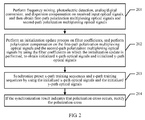
- an embodiment of a method for processing optical signals of the present invention includes the following steps.
- an apparatus for processing optical signals may receive input optical signals, and then perform frequency mixing, photoelectric detection, analog/digital conversion, and dispersion compensation on the input optical signals and local oscillation optical signals generated by a local laser, to obtain the first-path polarization multiplexing optical signals and the second-path polarization multiplexing optical signals.
- a polarization compensator in the apparatus for processing optical signals may adopt an adaptive filter for implementation, and may perform an initialization update process on filter coefficients of the polarization compensator after obtaining the first-path electrical signals and the second-path electrical signals, and further perform polarization compensation on the first-path electrical signals and the second-path electrical signals by using the filter coefficients on which the initialization update is performed, to obtain initialized x-path optical signals and initialized y-path optical signals.
- the apparatus for processing optical signals may synchronize the preset x-path training sequences and y-path training sequences by using the initialized x-path electrical signals and the initialized y-path electrical signals.
- the apparatus for processing optical signals is preset with the x-path training sequences and y-path training sequences.
- the apparatus for processing optical signals synchronizes the preset x-path training sequences and y-path training sequences by using the initialized x-path electrical signals and the initialized y-path electrical signals, and then may determine whether polarization swapping occurs according to the synchronization result. If the polarization swapping occurs, the apparatus for processing optical signals may rectify the polarization swapping.
- the apparatus for processing optical signals may first perform polarization compensation on the first-path electrical signals and the second-path electrical signals, and then perform synchronization of the training sequences. Since the optical signals of different paths may be separated through the polarization compensation, during synchronization of the training sequences, impairment of the optical signals may not affect the synchronization, thereby effectively improving synchronization stability of the optical signals.
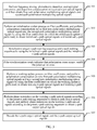
- FIG. 3 another embodiment of the method for processing optical signals of the present invention includes the following steps.
- an apparatus for processing optical signals may receive the input optical signals, and then input the input optical signals and local oscillation optical signals generated by a local laser into two frequency mixers for frequency mixing processing to obtain four paths of frequency mixing signals.
- the four paths of frequency mixing signals are input into four photoelectric detectors respectively for photoelectric detection, and then four paths of detection signals are output after completion of the photoelectric detection.
- the four paths of detection signals are input into four analog/digital converters respectively for analog/digital conversion, and four paths of digital signals are output after completion of the analog/digital conversion, which are I x , Q x , I y , and Q y , respectively.
- I x and Q x are input into one dispersion compensator for dispersion compensation, and then first-path electrical signals are output.
- I y and Q y are input into another dispersion compensator for dispersion compensation, and then second-path electrical signals are output.
- a polarization compensator in the apparatus for processing optical signals may adopt an adaptive filter for implementation, and may perform an initialization update process on filter coefficients of the polarization compensator after obtaining the first-path electrical signals and the second-path electrical signals.
- the initialization update process refers to update of the filter coefficients in an initialization state. It should be noted that, upon a startup operation, the apparatus for processing optical signals in this embodiment may first get into an initialization state to perform operations such as parameter debug and rectification of polarization swapping.
- polarization compensation may be performed on the first-path electrical signals by using the filter coefficients of an x-path filter which have undergone the initialization update, to obtain initialized x-path optical signals
- polarization compensation may be performed on the second-path electrical signals by using the filter coefficients of a y-path filter which have undergone the initialization update, to obtain initialized y-path optical signals.
- the initialization update process in this embodiment may specifically adopt blind equalization coefficient update, and the specific update manner may be as follows.
- a constant modulus algorithm is applied, and the modulus of the initialized x-path electrical signals and the modulus of the initialized y-path optical signals are kept constant, where the initialized x-path electrical signals and the initialized y-path electrical signals are output by the polarization compensator. Since the input first-path electrical signals and the input second-path electrical signals may dynamically change, the filter coefficients may be updated according to a constant modulus principle.
- the blind equalization coefficient update may be blind equalization coefficient update without decision feedback.
- the apparatus for processing electrical signals may synchronize the preset x-path training sequences and the preset y-path training sequences by using the initialized x-path electrical signals and the initialized y-path electrical signals.
- the apparatus for processing optical signals is preset with the x-path training sequences and y-path training sequences.
- the specific synchronization process may be as follows.
- the initialized x-path electrical signals are correlated with the x-path training sequences to obtain a first correlated peak
- the initialized y-path electrical signals are correlated with the y-path training sequences to obtain a second correlated peak
- the initialized x-path electrical signals are correlated with the y-path training sequences to obtain a third correlated peak
- the initialized y-path electrical signals are correlated with the x-path training sequences to obtain a fourth correlated peak.
- the polarization swapping does not occur.
- the third correlated peak and the fourth correlated peak are both greater than or equal to the preset threshold, and the first correlated peak and the second correlated peak are both less than the preset threshold, it is determined that the polarization swapping occurs.
- the filter coefficients of the x-path filter and the filter coefficients of the y-path filter in the polarization compensator may be exchanged, that is, the filter coefficients of the x-path filter are swapped for the filter coefficients of the y-path filter.
- the x-path filter may be enabled to output the initialized x-path electrical signals and the y-path filter may be enabled to output the initialized y-path electrical signals, so as to rectify the polarization swapping.
- step 305 may be directly executed.
- the apparatus for processing optical signals may be switched to a working state. Then, the apparatus for processing optical signals performs processing such as frequency mixing, photoelectric detection, analog/digital conversion and dispersion compensation on newly received input optical signals in the same way, and obtains new first-path electrical signals and new second-path electrical signals.
- the apparatus for processing optical signals in the working state may perform the working update process on the filter coefficients of the polarization compensator.
- the working update process in this embodiment may specifically adopt blind equalization coefficient update, and the specific update manner may be as follows.
- a constant modulus algorithm is applied, and the modulus of the working x-path electrical signals and the modulus of the working y-path electrical signals are kept constant, where the working x-path electrical signals and the working y-path electrical signals are output by the polarization compensator. Since newly input first-path electrical signals and newly input second-path electrical signals may dynamically change, the filter coefficients may be updated according to a constant modulus principle.
- the blind equalization coefficient update may be blind equalization coefficient update without decision feedback or may also be blind equalization coefficient update with decision feedback.
- the working update process may be performed through other manners in addition to the adoption of blind equalization coefficient update, such as the adoption of training sequence auxiliary coefficient update, and the specific update manner may be as follows.
- the apparatus for processing optical signals updates the filter coefficients with the training sequences as a target, and makes them approximate the training sequences as much as possible.
- the filter coefficients of the x-path filter are updated by using the x-path training sequences, and the filter coefficients of the y-path filter are updated by using the y-path training sequences.
- the apparatus for processing electrical signals may perform phase restoration on the working x-path electrical signals according to the preset x-path training sequences to obtain x-path output electrical signals, and perform phase restoration on the working y-path electrical signals according to the preset y-path training sequences to obtain y-path output electrical signals.
- the specific phase restoration manner may be as follows.
- the apparatus for processing optical signals estimates an initial phase of the working x-path electrical signals by using periodical x-path training sequences, and then according to the initial phase of the working x-path electrical signals, tracks the phase change of the working x-path electrical signals by using a phase locked loop, so as to perform phase restoration.
- the apparatus for processing optical signals may decode the x-path output electrical signals and the y-path output electrical signals to obtain original electrical signals, and the specific process is not limited herein.
- the apparatus for processing optical signals may first perform polarization compensation on the first-path electrical signals and the second-path electrical signals, and then perform synchronization of the training sequences. Since the optical signals of different paths may be separated through the polarization compensation, during synchronization of the training sequences, impairment of the optical signals may not affect the synchronization, thereby effectively improving synchronization stability of the optical signals.
- the apparatus for processing optical signals may adopt blind equalization coefficient update or training sequence auxiliary coefficient update, so as to improve flexibility of the solution.
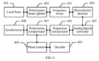
- an embodiment of the apparatus for processing optical signals of the present invention includes:
- the polarization compensator 407 in this embodiment may be further configured to perform a working update process on the filter coefficients, and perform polarization compensation on new first-path electrical signals and new second-path electrical signals by using the filter coefficients on which the working update is performed, to obtain working x-path electrical signals and working y-path electrical signals.
- the apparatus for processing optical signals in this embodiment may further include:
- the input optical signals are divided into x/y-path signals through a polarization beam splitter 502.
- the x/y-path signals are fed into 90° frequency mixers 503x and 503y, respectively, and meanwhile, a local laser 501 generates local oscillation optical signals.
- the local oscillation optical signals are divided into x/y-path signals through the polarization beam splitter 502 in the same way, and the x/y-path signals are fed into the 90° frequency mixers 503x and 503y, respectively.
- the 90° frequency mixers 503x and 503y each output two paths of frequency mixing signals.
- the four paths of frequency mixing signals are input into four photoelectric detectors 504 respectively for photoelectric detection, and then four paths of detection signals are output after completion of the photoelectric detection.
- the four paths of detection signals are input into four analog/digital converters 505 respectively for analog/digital conversion, and four paths of digital signals are output after completion of the analog/digital conversion, which are I x , Q x , I y , and Q y , respectively.
- I x and Q x are input into a dispersion compensator 506x for dispersion compensation, and then first-path electrical signals are output.
- I y and Q y are input into a dispersion compensator 506y for dispersion compensation, and then second-path electrical signals are output.
- An initialization update process is performed on filter coefficients of an adaptive filter in a polarization compensator 507, and the initialization update process refers to update of the filter coefficients in an initialization state. It should be noted that, upon the startup operation, the apparatus for processing optical signals in this embodiment may first get into an initialization state to perform operations such as parameter debug and rectification of polarization swapping.
- the initialization update process may specifically adopt blind equalization coefficient update, and the specific update manner may be as follows.
- a constant modulus algorithm is applied, and the modulus of the initialized x-path electrical signals and the modulus of the initialized y-path electrical signals are kept constant, where the initialized x-path electrical signals and the initialized y-path electrical signals are output by the polarization compensator. Since input first-path electrical signals and input second-path electrical signals may dynamically change, the filter coefficients may be updated according to a constant modulus principle.
- the blind equalization coefficient update may be blind equalization coefficient update without decision feedback.
- the obtained first-path electrical signals and the obtained second-path electrical signals may be input into the polarization compensator 507 simultaneously for polarization compensation.
- a specific structure of the polarization compensator 507 in this embodiment may be as shown in FIG. 6 , where W xx , W yx , W xy , and W yy are the filter coefficients of adaptive filters, W xx and W yx are filter coefficients of an x-path filter, and W xy and W yy are filter coefficients of a y-path filter.
- a synchronizer 508 may synchronize the preset x-path training sequences and the preset y-path training sequences by using the initialized x-path electrical signals and the initialized y-path electrical signals.
- the apparatus for processing optical signals is preset with the x-path training sequences and y-path training sequences.
- the specific synchronization process of the synchronizer 508 may be as follows.
- the initialized x-path electrical signals are correlated with the x-path training sequences to obtain a first correlated peak
- the initialized y-path electrical signals are correlated with the y-path training sequences to obtain a second correlated peak
- the initialized x-path electrical signals are correlated with the y-path training sequences to obtain a third correlated peak
- the initialized y-path electrical signals are correlated with the x-path training sequences to obtain a fourth correlated peak.
- the polarization swapping does not occur.
- the third correlated peak and the fourth correlated peak are both greater than or equal to the preset threshold, and the first correlated peak and the second correlated peak are both less than the preset threshold, it is determined that the polarization swapping occurs.
- the polarization compensator 507 may exchange the filter coefficients of the x-path filter for the filter coefficients of the y-path filter, that is, exchange W xx for W xy ; and exchange W yx for W yy , so that the x-path filter can output the initialized x-path electrical signals and the y-path filter can output the initialized y-path electrical signals, so as to rectify polarization swapping.
- the apparatus for processing optical signals may get into a working state from an initialization state.
- the local laser 501, the polarization beam splitter 502, the 90° frequency mixer 503x, the 90° frequency mixer 503y, the photoelectric detector 504, the analog/digital converter 505, the dispersion compensator 506x and the dispersion compensator 506y execute operations in the same processing manner as that for the apparatus for processing optical signals in the initialization state, and details are not described in detail herein again.
- the apparatus for processing optical signals in the working state may perform a working update process on the filter coefficients of the polarization compensator 507.
- the working update process in this embodiment may specifically adopt blind equalization coefficient update, and the specific update manner may be as follows.
- a constant modulus algorithm is applied, and the modulus of the working x-path electrical signals and the modulus of the working y-path electrical signals are kept constant, where the working x-path electrical signals and the working y-path electrical signals are output by the polarization compensator 507. Since newly input first-path electrical signals and newly input second-path electrical signals may dynamically change, the filter coefficients may be updated according to a constant modulus principle.
- the blind equalization coefficient update may be blind equalization coefficient update without decision feedback or may also be blind equalization coefficient update with decision feedback.
- the working update process may be performed through other manners in addition to adoption of the blind equalization coefficient update, such as adoption of training sequence auxiliary coefficient update, and the specific update manner may be as follows.
- the apparatus for processing optical signals updates the filter coefficients with the training sequences as a target, and makes them approximate the training sequences as much as possible.
- the filter coefficients of the x-path filter are updated by using the x-path training sequences, and the filter coefficients of the y-path filter are updated by using the y-path training sequences.
- a phase restorer 509x may perform phase restoration on the working x-path electrical signals according to the preset x-path training sequences to obtain x-path output electrical signals
- a phase restorer 509y may perform phase restoration on the working y-path electrical signals according to the preset y-path training sequences to obtain y-path output electrical signals.
- the specific phase restoration manner may be as follows.
- the phase restorer 509x estimates an initial phase of the working x-path electrical signals by using periodical x-path training sequences, and then according to the initial phase of the working x-path electrical signals, tracks the phase change of the working x-path electrical signals by using a phase locked loop, so as to perform phase restoration.
- phase restorer 509y performs phase restoration on the working y-path electrical signals.
- decoders 510x and 510y decode the x-path output electrical signals and the y-path output electrical signals respectively to obtain original electrical signals, and the specific process is not limited herein.
- the apparatus for processing optical signals may first perform polarization compensation on the first-path electrical signals and the second-path electrical signals, and then perform synchronization of the training sequences. Since the optical signals of different paths may be separated through the polarization compensation, during synchronization of the training sequences, impairment of the optical signals may not affect the synchronization, thereby effectively improving synchronization stability of the optical signals.
- the apparatus for processing optical signals may adopt blind equalization coefficient update or training sequence auxiliary coefficient update, so as to improve flexibility of the solution.
- the program may be stored in a computer readable storage medium, which may be a read-only memory, a magnetic disk, or an optical disk.
Landscapes
- Physics & Mathematics (AREA)
- Electromagnetism (AREA)
- Engineering & Computer Science (AREA)
- Computer Networks & Wireless Communication (AREA)
- Signal Processing (AREA)
- Optical Communication System (AREA)
Claims (9)
- Verfahren zum Verarbeiten optischer Signale, das Folgendes umfasst:Ausführen (201) durch einen Frequenzmischer von Frequenzmischen an empfangenen optischen Eingangssignalen;Ausführen durch einen photoelektrischen Detektor von photoelektrischer Detektion auf optischen Signalen, die durch den Frequenzmischer ausgegeben werden;Ausführen durch einen Analog/Digital-Umsetzer von Analog/Digital-Umsetzung an elektrischen Signalen, die durch den photoelektrischen Detektor ausgegeben werden;Ausführen durch einen Dispersionskompensator von Dispersionskompensation an digitalen Signalen, die aus dem Analog/Digital-Umsetzer ausgegeben werden, um elektrische Signale des ersten Pfads und elektrische Signale des zweiten Pfads zu erhalten;Ausführen (202) eines Initialisierungsaktualisierungsprozesses an Filterkoeffizienten eines Polarisationskompensators und Ausführen durch den Polarisationskompensator von Polarisationskompensation an den elektrischen Signalen des ersten Pfads und den elektrischen Signalen des zweiten Pfads durch Verwenden der Filterkoeffizienten, an denen die Initialisierungsaktualisierung ausgeführt worden ist, um initialisierte elektrische x-Pfad-Signale und initialisierte elektrische y-Pfad-Signale zu erhalten;wobei sich der Initialisierungsaktualisierungsprozess auf das Aktualisieren der Filterkoeffizienten in einem Initialisierungszustand bezieht;und dadurch gekennzeichnet, dass das Verfahren ferner Folgendes umfasst:Synchronisieren (203) voreingestellter x-Pfad-Trainingsfolgen und y-Pfad-Trainingsfolgen durch Verwenden der initialisierten elektrischen x-Pfad-Signale und der initialisierten elektrischen y-Pfad-Signale; undfalls ein Synchronisationsergebnis angibt, dass Polarisationswechsel auftritt, Korrigieren (204) des Polarisationswechsels; wobei das Korrigieren des Polarisationswechsels Folgendes umfasst: Austauschen der Filterkoeffizienten des x-Pfad-Filters durch die Filterkoeffizienten des y-Pfad-Filters.
- Verfahren nach Anspruch 1, wobei das Verfahren dann, wenn das Synchronisationsergebnis angibt, dass kein Polarisationswechsel auftritt, oder nachdem der Polarisationswechsel korrigiert worden ist, ferner Folgendes umfasst:Ausführen (305) eines Arbeitsaktualisierungsprozesses an den Filterkoeffizienten und Ausführen von Polarisationskompensation an neuen elektrischen Signalen des ersten Pfads und neuen elektrischen Signalen des zweiten Pfads durch Verwenden der Filterkoeffizienten, an denen die Arbeitsaktualisierung ausgeführt worden ist, um elektrische x-Pfad-Arbeitssignale und elektrische y-Pfad-Arbeitssignale zu erhalten;Ausführen (306) von Phasenwiederherstellung an den elektrischen x-Pfad-Arbeitssignalen gemäß den voreingestellten x-Pfad-Trainingsfolgen, um elektrische x-Pfad-Ausgangssignale zu erhalten, und Ausführen von Phasenwiederherstellung an den elektrischen y-Pfad-Arbeitssignalen gemäß den voreingestellten y-Pfad-Trainingsfolgen, um elektrische y-Pfad-Ausgangssignale zu erhalten; undDecodieren (307) der elektrischen x-Pfad-Ausgangssignale und der elektrischen y-Pfad-Ausgangssignale.
- Verfahren nach Anspruch 1 oder 2, wobei das Synchronisieren der voreingestellten x-Pfad-Trainingsfolgen und der voreingestellten y-Pfad-Trainingsfolgen durch Verwenden der initialisierten elektrischen x-Pfad-Signale und der initialisierten elektrischen y-Pfad-Signale Folgendes umfasst:Korrelieren der initialisierten elektrischen x-Pfad-Signale mit den x-Pfad-Trainingsfolgen, um eine erste korrelierte Spitze zu erhalten, Korrelieren der initialisierten elektrischen y-Pfad-Signale mit den y-Pfad-Trainingsfolgen, um eine zweite korrelierte Spitze zu erhalten, Korrelieren der initialisierten elektrischen x-Pfad-Signale mit den y-Pfad-Trainingsfolgen, um eine dritte korrelierte Spitze zu erhalten, und Korrelieren der initialisierten elektrischen y-Pfad-Signale mit den x-Pfad-Trainingsfolgen, um eine vierte korrelierte Spitze zu erhalten.
- Verfahren nach Anspruch 3, das ferner Folgendes umfasst:falls die erste korrelierte Spitze und die zweite korrelierte Spitze beide größer oder gleich einem voreingestellten Schwellenwert sind und die dritte korrelierte Spitze und die vierte korrelierte Spitze beide kleiner als der voreingestellte Schwellenwert sind, Bestimmen, dass kein Polarisationswechsel auftritt;falls die dritte korrelierte Spitze und die vierte korrelierte Spitze beide größer oder gleich dem voreingestellten Schwellenwert sind und die erste korrelierte Spitze und die zweite korrelierte Spitze beide kleiner als der voreingestellte Schwellenwert sind, Bestimmen, dass der Polarisationswechsel auftritt.
- Verfahren nach Anspruch 1 oder 2, wobei das Ausführen des Initialisierungsaktualisierungsprozesses an den Filterkoeffizienten Folgendes umfasst:Ausführen von Blindentzerrungskoeffizientenaktualisierung an Filterkoeffizienten eines x-Pfad-Filters und Filterkoeffizienten eines y-Pfad-Filters in einem Polarisationskompensator.
- Verfahren nach Anspruch 5, wobei das Ausführen der Polarisationskompensation an den elektrischen Signalen des ersten Pfads und den elektrischen Signalen des zweiten Pfads durch Verwenden der Filterkoeffizienten, an denen die Initialisierungsaktualisierung ausgeführt worden ist, um die initialisierten elektrischen x-Pfad-Signale und die initialisierten elektrischen y-Pfad-Signale zu erhalten, Folgendes umfasst:Ausführen der Polarisationskompensation an den elektrischen Signalen des ersten Pfads durch Verwenden der Filterkoeffizienten des x-Pfad-Filters, die die Initialisierungsaktualisierung durchlaufen haben, um die initialisierten elektrischen x-Pfad-Signale zu erhalten, und Ausführen der Polarisationskompensation an den elektrischen Signalen des zweiten Pfads durch Verwenden der Filterkoeffizienten des y-Pfad-Filters, die die Initialisierungsaktualisierung durchlaufen haben, um die initialisierten elektrischen y-Pfad-Signale zu erhalten.
- Verfahren nach Anspruch 2, wobei das Ausführen des Arbeitsaktualisierungsprozesses an den Filterkoeffizienten Folgendes umfasst:Ausführen von Blindentzerrungskoeffizientenaktualisierung an Filterkoeffizienten eines x-Pfad-Filters und Filterkoeffizienten eines y-Pfad-Filters in einem Polarisationskompensator;oderAusführen von Trainingsfolgenzusatzkoeffizientenaktualisierung an Filterkoeffizienten eines x-Pfad-Filters und Filterkoeffizienten eines y-Pfad-Filters in einem Polarisationskompensator.
- Vorrichtung zum Verarbeiten optischer Signale, die Folgendes umfasst:einen Frequenzmischer (103), der konfiguriert ist, Frequenzmischen an empfangenen optischen Eingangssignalen auszuführen;einen photoelektrischen Detektor (104), der konfiguriert ist, photoelektrische Detektion an optischen Signalen auszuführen, die durch die Frequenzmischer (103) ausgegeben werden;einen Analog/Digital-Umsetzer (105), der konfiguriert ist, Analog/Digital-Umsetzung an elektrischen Signalen auszuführen, die durch den photoelektrischen Detektor (104) ausgegeben werden;einen Dispersionskompensator (106), der konfiguriert ist, Dispersionskompensation an digitalen Signalen auszuführen, die durch den Analog/Digital-Umsetzer (105) ausgegeben werden, um elektrische Signale des ersten Pfads und elektrische Signale des zweiten Pfads zu erhalten;einen Polarisationskompensator (107), der konfiguriert ist, einen Initialisierungsaktualisierungsprozess an Filterkoeffizienten auszuführen und Polarisationskompensation an den elektrischen Signalen des ersten Pfads und elektrischen Signalen des zweiten Pfads auszuführen durch Verwenden der Filterkoeffizienten, an denen die Initialisierungsaktualisierung ausgeführt worden ist,um initialisierte elektrische x-Pfad-Signale und initialisierte elektrische y-Pfad-Signale zu erhalten; wobei sich der Initialisierungsaktualisierungsprozess auf das Aktualisieren der Filterkoeffizienten in einem Initialisierungszustand bezieht; unddadurch gekennzeichnet, dass die Vorrichtung ferner Folgendes umfasst:eine Synchronisationseinheit (110), die konfiguriert ist, voreingestellte x-Pfad-Trainingsfolgen und y-Pfad-Trainingsfolgen durch Verwenden der initialisierten elektrischen x-Pfad-Signale und der initialisierten elektrischen y-Pfad-Signale zu synchronisieren, und falls ein Synchronisationsergebnis angibt, dass Polarisationswechsel auftritt, den Polarisationswechsel zu korrigierten; wobei das Korrigieren des Polarisationswechsels Folgendes umfasst: Austauschen der Filterkoeffizienten des x-Pfad-Filters durch die Filterkoeffizienten des y-Pfad-Filters.
- Vorrichtung zum Verarbeiten optischer Signale nach Anspruch 8, wobei der Polarisationskompensator (107) ferner konfiguriert ist, einen Arbeitsaktualisierungsprozess an den Filterkoeffizienten auszuführen und Polarisationskompensation an neuen elektrischen Signalen des ersten Pfads und neuen elektrischen Signalen des zweiten Pfads durch Verwenden der Filterkoeffizienten, an denen die Arbeitsaktualisierung ausgeführt worden ist, auszuführen, um elektrische x-Pfad-Arbeitssignale und elektrische y-Pfad-Arbeitssignale zu erhalten; und die Vorrichtung zum Verarbeiten optischer Signale ferner Folgendes umfasst:eine Phasenwiederherstellungseinheit (108), die konfiguriert ist, eine Phasenwiederherstellung an den elektrischen x-Pfad-Arbeitssignalen gemäß den voreingestellten x-Pfad-Trainingsfolgen auszuführen, um elektrische x-Pfad-Ausgangssignale zu erhalten, und Phasenwiederherstellung an den elektrischen y-Pfad-Arbeitssignalen gemäß den voreingestellten y-Pfad-Trainingsfolgen auszuführen, um elektrische y-Pfad-Ausgangssignale zu erhalten; undeinen Decodierer (109), der konfiguriert ist, die elektrischen x-Pfad-Ausgangssignale und die elektrischen y-Pfad-Ausgangssignale zu decodieren.
Applications Claiming Priority (1)
| Application Number | Priority Date | Filing Date | Title |
|---|---|---|---|
| PCT/CN2011/074979 WO2011157128A2 (zh) | 2011-05-31 | 2011-05-31 | 光信号处理方法及装置 |
Publications (3)
| Publication Number | Publication Date |
|---|---|
| EP2685642A2 EP2685642A2 (de) | 2014-01-15 |
| EP2685642A4 EP2685642A4 (de) | 2014-09-03 |
| EP2685642B1 true EP2685642B1 (de) | 2016-08-31 |
Family
ID=44662798
Family Applications (1)
| Application Number | Title | Priority Date | Filing Date |
|---|---|---|---|
| EP11795094.9A Active EP2685642B1 (de) | 2011-05-31 | 2011-05-31 | Verfahren und vorrichtung zur verarbeitung optischer signale |
Country Status (5)
| Country | Link |
|---|---|
| US (1) | US8995831B2 (de) |
| EP (1) | EP2685642B1 (de) |
| CN (1) | CN102204133B (de) |
| ES (1) | ES2605306T3 (de) |
| WO (1) | WO2011157128A2 (de) |
Cited By (1)
| Publication number | Priority date | Publication date | Assignee | Title |
|---|---|---|---|---|
| EP4618447A1 (de) * | 2024-03-15 | 2025-09-17 | Nokia Solutions and Networks Oy | Doppelpolarisationsausrichtung |
Families Citing this family (12)
| Publication number | Priority date | Publication date | Assignee | Title |
|---|---|---|---|---|
| US8929750B2 (en) * | 2009-05-18 | 2015-01-06 | Nippon Telegraph And Telephone Corporation | Signal generating circuit, optical signal transmitting apparatus, signal receiving circuit, method for establishing optical signal synchronization, and optical signal synchronization system |
| EP2685642B1 (de) * | 2011-05-31 | 2016-08-31 | Huawei Technologies Co., Ltd. | Verfahren und vorrichtung zur verarbeitung optischer signale |
| CN102308546B (zh) * | 2011-07-26 | 2013-12-04 | 华为技术有限公司 | 一种多载波光信号的接收方法和装置 |
| US9413456B2 (en) * | 2012-07-20 | 2016-08-09 | The Boeing Company | Non-linear optical receiver |
| US8861960B2 (en) * | 2012-08-20 | 2014-10-14 | Ciena Corporation | Systems and methods for the compensation of nonlinear cross polarization and cross phase modulation in dual polarization coherent channels |
| JP6023671B2 (ja) * | 2013-07-29 | 2016-11-09 | 日本電信電話株式会社 | クロストーク補償装置、及び、クロストーク補償方法 |
| US10129054B2 (en) | 2017-02-10 | 2018-11-13 | Futurewei Technologies, Inc. | Training sequences with enhanced IQ imbalance tolerances for training-aided frequency domain equalization |
| CN108123908B (zh) * | 2017-12-14 | 2020-10-27 | 杭州电子科技大学 | 一种用于ng-pon的改进svm均衡方法及系统 |
| CN110149284B (zh) * | 2018-02-12 | 2022-08-26 | 华为技术有限公司 | 一种信道损伤估计方法与装置 |
| US10651947B2 (en) * | 2018-02-20 | 2020-05-12 | Futurewei Technologies, Inc. | Coherent detection with remotely delivered local oscillators |
| US10509167B2 (en) | 2018-04-23 | 2019-12-17 | Hewlett Packard Enterprise Development Lp | Optical phase difference calculation using analog processing |
| CN110224761B (zh) * | 2019-05-30 | 2020-08-04 | 武汉邮电科学研究院有限公司 | 一种快速求解偏振旋转矩阵和均衡器系数的方法及系统 |
Family Cites Families (38)
| Publication number | Priority date | Publication date | Assignee | Title |
|---|---|---|---|---|
| WO1999028723A1 (en) * | 1997-11-28 | 1999-06-10 | Fujitsu Limited | Polarization mode dispersion measuring method, and a dispersion compensation control device and a dispersion compensation control method |
| DE19936254A1 (de) * | 1999-07-31 | 2001-02-01 | Alcatel Sa | Filter zur Bestimmung der Kreuzkorrelation, Empfänger und Methode zur Entzerrung von Signalen |
| DE10243141B4 (de) * | 2002-09-17 | 2006-05-11 | Siemens Ag | Verfahren zur Übertragung von optischen Polarisationsmultiplexsignalen |
| JP4053389B2 (ja) * | 2002-09-19 | 2008-02-27 | 富士通株式会社 | 光信号対雑音比のモニタ方法およびそれを用いた光伝送システム |
| US6947549B2 (en) * | 2003-02-19 | 2005-09-20 | The Hong Kong Polytechnic University | Echo canceller |
| ATE313175T1 (de) * | 2003-08-18 | 2005-12-15 | Cit Alcatel | Verfahren zur optischen übertragung und optischer empfänger |
| CN1902540A (zh) * | 2003-11-17 | 2007-01-24 | 财团法人大阪产业振兴机构 | 光信号处理方法和装置 |
| CN1295894C (zh) * | 2003-11-18 | 2007-01-17 | 北京邮电大学 | 自适应偏振模色散补偿中的反馈控制模块 |
| US7315575B2 (en) * | 2004-03-08 | 2008-01-01 | Nortel Networks Limited | Equalization strategy for dual-polarization optical transport system |
| US20060007197A1 (en) * | 2004-06-29 | 2006-01-12 | Gilbert John D | Apparatus and method for light signal processing utilizing independent timing signal |
| US7555227B2 (en) * | 2005-10-21 | 2009-06-30 | Nortel Networks Limited | Polarization compensation in a coherent optical receiver |
| US7606498B1 (en) * | 2005-10-21 | 2009-10-20 | Nortel Networks Limited | Carrier recovery in a coherent optical receiver |
| US7522841B2 (en) * | 2005-10-21 | 2009-04-21 | Nortel Networks Limited | Efficient data transmission and training of data processing functions |
| CN1790948A (zh) * | 2005-12-08 | 2006-06-21 | 上海交通大学 | 同步光传输系统中光信噪比监测的方法 |
| US8078065B2 (en) * | 2006-12-22 | 2011-12-13 | Alcatel Lucent | Polarization tracking and signal equalization for optical receivers configured for on-off keying or pulse amplitude modulation signaling |
| JP5003391B2 (ja) * | 2007-10-01 | 2012-08-15 | 富士通株式会社 | 光伝送システムおよび光伝送方法 |
| US8005368B2 (en) * | 2007-12-05 | 2011-08-23 | Ciena Corporation | Signal equalizer in a coherent optical receiver |
| US7701842B2 (en) * | 2008-02-13 | 2010-04-20 | Nortel Networks Limited | Low conversion rate digital dispersion compensation |
| JP5181770B2 (ja) * | 2008-03-27 | 2013-04-10 | 富士通株式会社 | 光伝送システム |
| CN101552640B (zh) * | 2008-04-01 | 2012-04-11 | 富士通株式会社 | 滤波器系数变更装置和方法 |
| CN101599801B (zh) * | 2008-06-06 | 2012-02-22 | 富士通株式会社 | 滤波器系数调整装置和方法 |
| US8233809B2 (en) * | 2008-10-28 | 2012-07-31 | Nec Laboratories America, Inc. | Polarization independent frequency domain equalization (FDE) for chromatic dispersion (CD) compensation in PolMux coherent systems |
| JP5141498B2 (ja) * | 2008-10-30 | 2013-02-13 | 富士通株式会社 | 光送受信システム,光送信器,光受信器および光送受信方法 |
| US8184993B2 (en) * | 2009-02-25 | 2012-05-22 | Nec Laboratories America, Inc. | Polarization mode dispersion (PMD) compensation in polarization multiplexed coded orthogonal frequency division multiplexing (OFDM) systems |
| WO2010136068A1 (en) * | 2009-05-28 | 2010-12-02 | Nokia Siemens Networks Gmbh & Co. Kg | Method and arrangement for blind demultiplexing a polarisation diversity multiplex signal |
| US8655191B2 (en) * | 2009-06-29 | 2014-02-18 | Alcatel Lucent | Symbol timing recovery in polarization division multiplexed coherent optical transmission system |
| KR20110005575A (ko) * | 2009-07-10 | 2011-01-18 | 한국전자통신연구원 | 코히어런트 광 수신기의 디지털 등화 장치 및 방법 |
| US8340534B2 (en) * | 2009-08-07 | 2012-12-25 | Futurewei Technologies, Inc. | Side band pilot tone for digital signal processing in polarization multiplexed coherent optical communication system |
| US8718491B2 (en) * | 2009-10-29 | 2014-05-06 | Ciena Corporation | Soft decoding of data in a coherent optical receiver |
| US9100126B2 (en) * | 2009-11-24 | 2015-08-04 | Nec Corporation | Optical reception device and optical reception control method |
| JP5350284B2 (ja) * | 2010-01-28 | 2013-11-27 | 株式会社日立製作所 | 光送受信システム及び光受信機 |
| US8538278B2 (en) * | 2010-02-09 | 2013-09-17 | NEC Laboratorie America, Inc | Superimposed training and digital filtering coherent optical receivers |
| CN102209055B (zh) * | 2010-03-30 | 2014-10-01 | 富士通株式会社 | 用于相移键控信号的自适应盲均衡方法、均衡器及接收机 |
| JP5549333B2 (ja) * | 2010-04-07 | 2014-07-16 | 富士通株式会社 | 偏波変動補償装置および光通信システム |
| US8472813B2 (en) * | 2010-06-18 | 2013-06-25 | Nec Laboratories America, Inc. | Computationally-efficient MIMO equalization algorithm for high-speed, real-time, adaptive polarization multiplexed (POLMUX) OFDM transmission with direct detection |
| US8744275B2 (en) * | 2011-03-05 | 2014-06-03 | LGS Innovations LLC | System, method, and apparatus for high-sensitivity optical detection |
| US8615171B2 (en) * | 2011-03-31 | 2013-12-24 | Nec Laboratories America, Inc. | Computationally-efficient equalization in polmux OFDM transmission with direct detection via joint transmitter and receiver processing |
| EP2685642B1 (de) * | 2011-05-31 | 2016-08-31 | Huawei Technologies Co., Ltd. | Verfahren und vorrichtung zur verarbeitung optischer signale |
-
2011
- 2011-05-31 EP EP11795094.9A patent/EP2685642B1/de active Active
- 2011-05-31 ES ES11795094.9T patent/ES2605306T3/es active Active
- 2011-05-31 WO PCT/CN2011/074979 patent/WO2011157128A2/zh not_active Ceased
- 2011-05-31 CN CN201180000521.1A patent/CN102204133B/zh active Active
-
2012
- 2012-10-30 US US13/664,134 patent/US8995831B2/en active Active
Cited By (1)
| Publication number | Priority date | Publication date | Assignee | Title |
|---|---|---|---|---|
| EP4618447A1 (de) * | 2024-03-15 | 2025-09-17 | Nokia Solutions and Networks Oy | Doppelpolarisationsausrichtung |
Also Published As
| Publication number | Publication date |
|---|---|
| WO2011157128A3 (zh) | 2012-04-05 |
| EP2685642A2 (de) | 2014-01-15 |
| US20130058649A1 (en) | 2013-03-07 |
| EP2685642A4 (de) | 2014-09-03 |
| ES2605306T3 (es) | 2017-03-13 |
| CN102204133B (zh) | 2014-02-26 |
| WO2011157128A2 (zh) | 2011-12-22 |
| US8995831B2 (en) | 2015-03-31 |
| CN102204133A (zh) | 2011-09-28 |
Similar Documents
| Publication | Publication Date | Title |
|---|---|---|
| EP2685642B1 (de) | Verfahren und vorrichtung zur verarbeitung optischer signale | |
| US9413522B2 (en) | Optical receiver and signal processing method for optical receiver | |
| EP2357740B1 (de) | Optischer Empfänger | |
| US6198559B1 (en) | Automatic delay compensation for generating NRZ signals from RZ signals in communications networks | |
| EP1959590B1 (de) | Steuerung für Analog-Digital-Umwandlung, optische Empfangsvorrichtung und optisches Empfangsverfahren | |
| US9686020B2 (en) | Signal processing device and signal processing method | |
| US8725007B2 (en) | Method and arrangement for adaptive dispersion compensation | |
| US8693898B2 (en) | Adaptive equalizer, optical receiver, and tap coefficient correcting method | |
| US8831081B2 (en) | Digital filter device, digital filtering method and control program for the digital filter device | |
| US10998973B2 (en) | Signal combining device and signal combining method | |
| US20130251370A1 (en) | Optical receiver, polarization separation device and polarization separating method | |
| US20190280778A1 (en) | Pilot-Aided Digital Signal Processing for Reception of Coherent Optical Communication | |
| KR20110005575A (ko) | 코히어런트 광 수신기의 디지털 등화 장치 및 방법 | |
| WO2012118215A1 (ja) | 光受信器、偏波分離装置、および光受信方法 | |
| KR20120065726A (ko) | 광 수신 신호의 디지털 등화를 수행하는 코히어런트 광 수신 장치 및 방법과 코히어런트 광 송수신 장치 | |
| JP2017028359A (ja) | 光受信装置およびタップ係数の更新方法 | |
| US11303381B2 (en) | Processing parameter and resource sharing architecture for superchannel based transmission systems | |
| KR101322929B1 (ko) | Dqpsk 변조를 근거한 위상차의 모니터 및 제어 방법 및 장치 | |
| US10771230B2 (en) | Estimating apparatus for bias drift of transmitting end modulator, compensating apparatus and receiver | |
| KR101314844B1 (ko) | 코히어런트 광 수신기의 디지털 신호 동기화 장치 | |
| EP3133751A1 (de) | Verfahren zur nichtlinearitätskompensierung in optischen übertragungssystemen | |
| JP7634785B1 (ja) | 光受信器、光受信方法、光受信プログラム、および記録媒体 | |
| US20240250770A1 (en) | Optical transmission apparatus, system, method, and non-transitory computer readable medium | |
| JP2019165392A (ja) | 遅延調整装置 | |
| US20260100764A1 (en) | Signal processing circuit, optical signal receiving device, and signal processing method |
Legal Events
| Date | Code | Title | Description |
|---|---|---|---|
| PUAI | Public reference made under article 153(3) epc to a published international application that has entered the european phase |
Free format text: ORIGINAL CODE: 0009012 |
|
| 17P | Request for examination filed |
Effective date: 20120716 |
|
| AK | Designated contracting states |
Kind code of ref document: A2 Designated state(s): AL AT BE BG CH CY CZ DE DK EE ES FI FR GB GR HR HU IE IS IT LI LT LU LV MC MK MT NL NO PL PT RO RS SE SI SK SM TR |
|
| REG | Reference to a national code |
Ref country code: DE Ref legal event code: R079 Ref document number: 602011029912 Country of ref document: DE Free format text: PREVIOUS MAIN CLASS: H04B0010180000 Ipc: H04B0010250700 |
|
| A4 | Supplementary search report drawn up and despatched |
Effective date: 20140801 |
|
| DAX | Request for extension of the european patent (deleted) | ||
| RIC1 | Information provided on ipc code assigned before grant |
Ipc: H04B 10/2507 20130101AFI20140728BHEP |
|
| 17Q | First examination report despatched |
Effective date: 20150716 |
|
| GRAP | Despatch of communication of intention to grant a patent |
Free format text: ORIGINAL CODE: EPIDOSNIGR1 |
|
| INTG | Intention to grant announced |
Effective date: 20160308 |
|
| RIN1 | Information on inventor provided before grant (corrected) |
Inventor name: LI, LIANGCHUAN Inventor name: LIU, LING |
|
| GRAS | Grant fee paid |
Free format text: ORIGINAL CODE: EPIDOSNIGR3 |
|
| GRAA | (expected) grant |
Free format text: ORIGINAL CODE: 0009210 |
|
| AK | Designated contracting states |
Kind code of ref document: B1 Designated state(s): AL AT BE BG CH CY CZ DE DK EE ES FI FR GB GR HR HU IE IS IT LI LT LU LV MC MK MT NL NO PL PT RO RS SE SI SK SM TR |
|
| REG | Reference to a national code |
Ref country code: CH Ref legal event code: EP Ref country code: GB Ref legal event code: FG4D |
|
| REG | Reference to a national code |
Ref country code: IE Ref legal event code: FG4D |
|
| REG | Reference to a national code |
Ref country code: DE Ref legal event code: R096 Ref document number: 602011029912 Country of ref document: DE |
|
| REG | Reference to a national code |
Ref country code: AT Ref legal event code: REF Ref document number: 825779 Country of ref document: AT Kind code of ref document: T Effective date: 20161015 |
|
| REG | Reference to a national code |
Ref country code: LT Ref legal event code: MG4D |
|
| REG | Reference to a national code |
Ref country code: NL Ref legal event code: MP Effective date: 20160831 |
|
| REG | Reference to a national code |
Ref country code: AT Ref legal event code: MK05 Ref document number: 825779 Country of ref document: AT Kind code of ref document: T Effective date: 20160831 |
|
| PG25 | Lapsed in a contracting state [announced via postgrant information from national office to epo] |
Ref country code: RS Free format text: LAPSE BECAUSE OF FAILURE TO SUBMIT A TRANSLATION OF THE DESCRIPTION OR TO PAY THE FEE WITHIN THE PRESCRIBED TIME-LIMIT Effective date: 20160831 Ref country code: FI Free format text: LAPSE BECAUSE OF FAILURE TO SUBMIT A TRANSLATION OF THE DESCRIPTION OR TO PAY THE FEE WITHIN THE PRESCRIBED TIME-LIMIT Effective date: 20160831 Ref country code: LT Free format text: LAPSE BECAUSE OF FAILURE TO SUBMIT A TRANSLATION OF THE DESCRIPTION OR TO PAY THE FEE WITHIN THE PRESCRIBED TIME-LIMIT Effective date: 20160831 Ref country code: HR Free format text: LAPSE BECAUSE OF FAILURE TO SUBMIT A TRANSLATION OF THE DESCRIPTION OR TO PAY THE FEE WITHIN THE PRESCRIBED TIME-LIMIT Effective date: 20160831 Ref country code: NO Free format text: LAPSE BECAUSE OF FAILURE TO SUBMIT A TRANSLATION OF THE DESCRIPTION OR TO PAY THE FEE WITHIN THE PRESCRIBED TIME-LIMIT Effective date: 20161130 |
|
| PG25 | Lapsed in a contracting state [announced via postgrant information from national office to epo] |
Ref country code: AT Free format text: LAPSE BECAUSE OF FAILURE TO SUBMIT A TRANSLATION OF THE DESCRIPTION OR TO PAY THE FEE WITHIN THE PRESCRIBED TIME-LIMIT Effective date: 20160831 Ref country code: SE Free format text: LAPSE BECAUSE OF FAILURE TO SUBMIT A TRANSLATION OF THE DESCRIPTION OR TO PAY THE FEE WITHIN THE PRESCRIBED TIME-LIMIT Effective date: 20160831 Ref country code: GR Free format text: LAPSE BECAUSE OF FAILURE TO SUBMIT A TRANSLATION OF THE DESCRIPTION OR TO PAY THE FEE WITHIN THE PRESCRIBED TIME-LIMIT Effective date: 20161201 Ref country code: LV Free format text: LAPSE BECAUSE OF FAILURE TO SUBMIT A TRANSLATION OF THE DESCRIPTION OR TO PAY THE FEE WITHIN THE PRESCRIBED TIME-LIMIT Effective date: 20160831 Ref country code: NL Free format text: LAPSE BECAUSE OF FAILURE TO SUBMIT A TRANSLATION OF THE DESCRIPTION OR TO PAY THE FEE WITHIN THE PRESCRIBED TIME-LIMIT Effective date: 20160831 |
|
| REG | Reference to a national code |
Ref country code: ES Ref legal event code: FG2A Ref document number: 2605306 Country of ref document: ES Kind code of ref document: T3 Effective date: 20170313 |
|
| REG | Reference to a national code |
Ref country code: FR Ref legal event code: PLFP Year of fee payment: 7 |
|
| PG25 | Lapsed in a contracting state [announced via postgrant information from national office to epo] |
Ref country code: RO Free format text: LAPSE BECAUSE OF FAILURE TO SUBMIT A TRANSLATION OF THE DESCRIPTION OR TO PAY THE FEE WITHIN THE PRESCRIBED TIME-LIMIT Effective date: 20160831 Ref country code: EE Free format text: LAPSE BECAUSE OF FAILURE TO SUBMIT A TRANSLATION OF THE DESCRIPTION OR TO PAY THE FEE WITHIN THE PRESCRIBED TIME-LIMIT Effective date: 20160831 |
|
| PG25 | Lapsed in a contracting state [announced via postgrant information from national office to epo] |
Ref country code: BG Free format text: LAPSE BECAUSE OF FAILURE TO SUBMIT A TRANSLATION OF THE DESCRIPTION OR TO PAY THE FEE WITHIN THE PRESCRIBED TIME-LIMIT Effective date: 20161130 Ref country code: BE Free format text: LAPSE BECAUSE OF FAILURE TO SUBMIT A TRANSLATION OF THE DESCRIPTION OR TO PAY THE FEE WITHIN THE PRESCRIBED TIME-LIMIT Effective date: 20160831 Ref country code: DK Free format text: LAPSE BECAUSE OF FAILURE TO SUBMIT A TRANSLATION OF THE DESCRIPTION OR TO PAY THE FEE WITHIN THE PRESCRIBED TIME-LIMIT Effective date: 20160831 Ref country code: CZ Free format text: LAPSE BECAUSE OF FAILURE TO SUBMIT A TRANSLATION OF THE DESCRIPTION OR TO PAY THE FEE WITHIN THE PRESCRIBED TIME-LIMIT Effective date: 20160831 Ref country code: PT Free format text: LAPSE BECAUSE OF FAILURE TO SUBMIT A TRANSLATION OF THE DESCRIPTION OR TO PAY THE FEE WITHIN THE PRESCRIBED TIME-LIMIT Effective date: 20170102 Ref country code: SK Free format text: LAPSE BECAUSE OF FAILURE TO SUBMIT A TRANSLATION OF THE DESCRIPTION OR TO PAY THE FEE WITHIN THE PRESCRIBED TIME-LIMIT Effective date: 20160831 Ref country code: PL Free format text: LAPSE BECAUSE OF FAILURE TO SUBMIT A TRANSLATION OF THE DESCRIPTION OR TO PAY THE FEE WITHIN THE PRESCRIBED TIME-LIMIT Effective date: 20160831 Ref country code: SM Free format text: LAPSE BECAUSE OF FAILURE TO SUBMIT A TRANSLATION OF THE DESCRIPTION OR TO PAY THE FEE WITHIN THE PRESCRIBED TIME-LIMIT Effective date: 20160831 |
|
| REG | Reference to a national code |
Ref country code: DE Ref legal event code: R097 Ref document number: 602011029912 Country of ref document: DE |
|
| PG25 | Lapsed in a contracting state [announced via postgrant information from national office to epo] |
Ref country code: IT Free format text: LAPSE BECAUSE OF FAILURE TO SUBMIT A TRANSLATION OF THE DESCRIPTION OR TO PAY THE FEE WITHIN THE PRESCRIBED TIME-LIMIT Effective date: 20160831 |
|
| PLBE | No opposition filed within time limit |
Free format text: ORIGINAL CODE: 0009261 |
|
| STAA | Information on the status of an ep patent application or granted ep patent |
Free format text: STATUS: NO OPPOSITION FILED WITHIN TIME LIMIT |
|
| 26N | No opposition filed |
Effective date: 20170601 |
|
| PG25 | Lapsed in a contracting state [announced via postgrant information from national office to epo] |
Ref country code: LU Free format text: LAPSE BECAUSE OF NON-PAYMENT OF DUE FEES Effective date: 20170531 Ref country code: SI Free format text: LAPSE BECAUSE OF FAILURE TO SUBMIT A TRANSLATION OF THE DESCRIPTION OR TO PAY THE FEE WITHIN THE PRESCRIBED TIME-LIMIT Effective date: 20160831 |
|
| REG | Reference to a national code |
Ref country code: CH Ref legal event code: PL |
|
| PG25 | Lapsed in a contracting state [announced via postgrant information from national office to epo] |
Ref country code: MC Free format text: LAPSE BECAUSE OF FAILURE TO SUBMIT A TRANSLATION OF THE DESCRIPTION OR TO PAY THE FEE WITHIN THE PRESCRIBED TIME-LIMIT Effective date: 20160831 |
|
| REG | Reference to a national code |
Ref country code: IE Ref legal event code: MM4A |
|
| PG25 | Lapsed in a contracting state [announced via postgrant information from national office to epo] |
Ref country code: CH Free format text: LAPSE BECAUSE OF NON-PAYMENT OF DUE FEES Effective date: 20170531 Ref country code: LI Free format text: LAPSE BECAUSE OF NON-PAYMENT OF DUE FEES Effective date: 20170531 |
|
| REG | Reference to a national code |
Ref country code: FR Ref legal event code: PLFP Year of fee payment: 8 |
|
| PG25 | Lapsed in a contracting state [announced via postgrant information from national office to epo] |
Ref country code: IE Free format text: LAPSE BECAUSE OF NON-PAYMENT OF DUE FEES Effective date: 20170531 |
|
| PG25 | Lapsed in a contracting state [announced via postgrant information from national office to epo] |
Ref country code: MT Free format text: LAPSE BECAUSE OF NON-PAYMENT OF DUE FEES Effective date: 20170531 |
|
| PG25 | Lapsed in a contracting state [announced via postgrant information from national office to epo] |
Ref country code: AL Free format text: LAPSE BECAUSE OF FAILURE TO SUBMIT A TRANSLATION OF THE DESCRIPTION OR TO PAY THE FEE WITHIN THE PRESCRIBED TIME-LIMIT Effective date: 20160831 |
|
| PG25 | Lapsed in a contracting state [announced via postgrant information from national office to epo] |
Ref country code: HU Free format text: LAPSE BECAUSE OF FAILURE TO SUBMIT A TRANSLATION OF THE DESCRIPTION OR TO PAY THE FEE WITHIN THE PRESCRIBED TIME-LIMIT; INVALID AB INITIO Effective date: 20110531 |
|
| PG25 | Lapsed in a contracting state [announced via postgrant information from national office to epo] |
Ref country code: CY Free format text: LAPSE BECAUSE OF NON-PAYMENT OF DUE FEES Effective date: 20160831 |
|
| PG25 | Lapsed in a contracting state [announced via postgrant information from national office to epo] |
Ref country code: MK Free format text: LAPSE BECAUSE OF FAILURE TO SUBMIT A TRANSLATION OF THE DESCRIPTION OR TO PAY THE FEE WITHIN THE PRESCRIBED TIME-LIMIT Effective date: 20160831 |
|
| PG25 | Lapsed in a contracting state [announced via postgrant information from national office to epo] |
Ref country code: TR Free format text: LAPSE BECAUSE OF FAILURE TO SUBMIT A TRANSLATION OF THE DESCRIPTION OR TO PAY THE FEE WITHIN THE PRESCRIBED TIME-LIMIT Effective date: 20160831 |
|
| PG25 | Lapsed in a contracting state [announced via postgrant information from national office to epo] |
Ref country code: IS Free format text: LAPSE BECAUSE OF FAILURE TO SUBMIT A TRANSLATION OF THE DESCRIPTION OR TO PAY THE FEE WITHIN THE PRESCRIBED TIME-LIMIT Effective date: 20161231 |
|
| REG | Reference to a national code |
Ref country code: FR Ref legal event code: PLFP Year of fee payment: 13 |
|
| PGFP | Annual fee paid to national office [announced via postgrant information from national office to epo] |
Ref country code: DE Payment date: 20250402 Year of fee payment: 15 |
|
| PGFP | Annual fee paid to national office [announced via postgrant information from national office to epo] |
Ref country code: ES Payment date: 20250605 Year of fee payment: 15 |
|
| PGFP | Annual fee paid to national office [announced via postgrant information from national office to epo] |
Ref country code: FR Payment date: 20250401 Year of fee payment: 15 |
|
| PGFP | Annual fee paid to national office [announced via postgrant information from national office to epo] |
Ref country code: GB Payment date: 20260324 Year of fee payment: 16 |