EP2685718A1 - Appareil de décodage d'image, appareil de codage d'image et structure de données codées - Google Patents
Appareil de décodage d'image, appareil de codage d'image et structure de données codées Download PDFInfo
- Publication number
- EP2685718A1 EP2685718A1 EP12754367.6A EP12754367A EP2685718A1 EP 2685718 A1 EP2685718 A1 EP 2685718A1 EP 12754367 A EP12754367 A EP 12754367A EP 2685718 A1 EP2685718 A1 EP 2685718A1
- Authority
- EP
- European Patent Office
- Prior art keywords
- information
- merge
- transform coefficients
- flag
- image
- Prior art date
- Legal status (The legal status is an assumption and is not a legal conclusion. Google has not performed a legal analysis and makes no representation as to the accuracy of the status listed.)
- Granted
Links
Images








Classifications
-
- H—ELECTRICITY
- H04—ELECTRIC COMMUNICATION TECHNIQUE
- H04N—PICTORIAL COMMUNICATION, e.g. TELEVISION
- H04N19/00—Methods or arrangements for coding, decoding, compressing or decompressing digital video signals
- H04N19/46—Embedding additional information in the video signal during the compression process
- H04N19/463—Embedding additional information in the video signal during the compression process by compressing encoding parameters before transmission
-
- H—ELECTRICITY
- H04—ELECTRIC COMMUNICATION TECHNIQUE
- H04N—PICTORIAL COMMUNICATION, e.g. TELEVISION
- H04N19/00—Methods or arrangements for coding, decoding, compressing or decompressing digital video signals
- H04N19/10—Methods or arrangements for coding, decoding, compressing or decompressing digital video signals using adaptive coding
- H04N19/102—Methods or arrangements for coding, decoding, compressing or decompressing digital video signals using adaptive coding characterised by the element, parameter or selection affected or controlled by the adaptive coding
- H04N19/103—Selection of coding mode or of prediction mode
- H04N19/11—Selection of coding mode or of prediction mode among a plurality of spatial predictive coding modes
-
- H—ELECTRICITY
- H04—ELECTRIC COMMUNICATION TECHNIQUE
- H04N—PICTORIAL COMMUNICATION, e.g. TELEVISION
- H04N19/00—Methods or arrangements for coding, decoding, compressing or decompressing digital video signals
- H04N19/10—Methods or arrangements for coding, decoding, compressing or decompressing digital video signals using adaptive coding
- H04N19/102—Methods or arrangements for coding, decoding, compressing or decompressing digital video signals using adaptive coding characterised by the element, parameter or selection affected or controlled by the adaptive coding
- H04N19/119—Adaptive subdivision aspects, e.g. subdivision of a picture into rectangular or non-rectangular coding blocks
-
- H—ELECTRICITY
- H04—ELECTRIC COMMUNICATION TECHNIQUE
- H04N—PICTORIAL COMMUNICATION, e.g. TELEVISION
- H04N19/00—Methods or arrangements for coding, decoding, compressing or decompressing digital video signals
- H04N19/10—Methods or arrangements for coding, decoding, compressing or decompressing digital video signals using adaptive coding
- H04N19/102—Methods or arrangements for coding, decoding, compressing or decompressing digital video signals using adaptive coding characterised by the element, parameter or selection affected or controlled by the adaptive coding
- H04N19/12—Selection from among a plurality of transforms or standards, e.g. selection between discrete cosine transform [DCT] and sub-band transform or selection between H.263 and H.264
- H04N19/122—Selection of transform size, e.g. 8x8 or 2x4x8 DCT; Selection of sub-band transforms of varying structure or type
-
- H—ELECTRICITY
- H04—ELECTRIC COMMUNICATION TECHNIQUE
- H04N—PICTORIAL COMMUNICATION, e.g. TELEVISION
- H04N19/00—Methods or arrangements for coding, decoding, compressing or decompressing digital video signals
- H04N19/10—Methods or arrangements for coding, decoding, compressing or decompressing digital video signals using adaptive coding
- H04N19/169—Methods or arrangements for coding, decoding, compressing or decompressing digital video signals using adaptive coding characterised by the coding unit, i.e. the structural portion or semantic portion of the video signal being the object or the subject of the adaptive coding
- H04N19/17—Methods or arrangements for coding, decoding, compressing or decompressing digital video signals using adaptive coding characterised by the coding unit, i.e. the structural portion or semantic portion of the video signal being the object or the subject of the adaptive coding the unit being an image region, e.g. an object
- H04N19/176—Methods or arrangements for coding, decoding, compressing or decompressing digital video signals using adaptive coding characterised by the coding unit, i.e. the structural portion or semantic portion of the video signal being the object or the subject of the adaptive coding the unit being an image region, e.g. an object the region being a block, e.g. a macroblock
-
- H—ELECTRICITY
- H04—ELECTRIC COMMUNICATION TECHNIQUE
- H04N—PICTORIAL COMMUNICATION, e.g. TELEVISION
- H04N19/00—Methods or arrangements for coding, decoding, compressing or decompressing digital video signals
- H04N19/46—Embedding additional information in the video signal during the compression process
-
- H—ELECTRICITY
- H04—ELECTRIC COMMUNICATION TECHNIQUE
- H04N—PICTORIAL COMMUNICATION, e.g. TELEVISION
- H04N19/00—Methods or arrangements for coding, decoding, compressing or decompressing digital video signals
- H04N19/60—Methods or arrangements for coding, decoding, compressing or decompressing digital video signals using transform coding
- H04N19/61—Methods or arrangements for coding, decoding, compressing or decompressing digital video signals using transform coding in combination with predictive coding
-
- H—ELECTRICITY
- H04—ELECTRIC COMMUNICATION TECHNIQUE
- H04N—PICTORIAL COMMUNICATION, e.g. TELEVISION
- H04N19/00—Methods or arrangements for coding, decoding, compressing or decompressing digital video signals
- H04N19/70—Methods or arrangements for coding, decoding, compressing or decompressing digital video signals characterised by syntax aspects related to video coding, e.g. related to compression standards
Definitions
- encoded data that includes various information subjected to Skip or Merge is limited to encoded data used in the case of decoding a CU, or encoded data used in the case of decoding a PU.
- the present invention has been devised in light of the above problems, and an object thereof is to realize an image encoding device and the like able to further reduce the code rate of encoded data.
- an image decoding device that decodes an image by decoding encoded data that includes encoded and quantized transform coefficients in which a prediction residual obtained by subtracting a predicted image from an original image is transformed and quantized per a transform unit, and the quantized transform coefficients are encoded.
- the image decoding device is equipped with decoding means that, for a partial unit obtained by splitting the transform unit, infers, or alternatively, decodes from the encoded data, non-zero transform coefficient presence information indicating whether or not non-zero transform coefficients are included in that partial unit, and in the case where the non-zero transform coefficient presence information indicates that non-zero transform coefficients are present within that partial unit, decodes each transform coefficient within the decoding unit that includes that partial unit from the encoded data.
- non-zero transform coefficient presence information is inferred or decoded, and in the case where the non-zero transform coefficient presence information indicates that non-zero transform coefficients are present, transform coefficients within a decoding unit that includes that partial unit are decoded.
- the determination of whether or not non-zero transform coefficients are present may be conducted for a partial unit.
- an image decoding device that decodes an image by decoding encoded data that includes encoded and quantized transform coefficients in which a prediction residual obtained by subtracting a predicted image from an original image is transformed and quantized per a transform unit, and the quantized transform coefficients are encoded.
- the image decoding device is equipped with decoding means that, in the case where the encoded data includes merge/skip information that merges or skips presence information indicating whether or not frequency-domain transform coefficients are included in the quantized transform coefficients, does not decode the presence information, and inferring means that, in the case where the encoded data includes merge/skip information that merges or skips the presence information, infers the presence information.
- the decoding means uses the presence information inferred by the inferring means to decode the encoded and quantized transform coefficients.
- merging refers to omitting particular information necessary for decoding, with the information being estimated on the basis of information at a default or a specified position.
- skipping refers to omitting particular information necessary for decoding, and using estimated values or default values instead.
- decoding may be conducted by transmitting only merge/skip information, without transmitting information indicating whether or not frequency-domain transform coefficients are present.
- an image decoding device that decodes an image by decoding encoded data that includes encoded and quantized transform coefficients in which a prediction residual obtained by subtracting a predicted image from an original image is transformed and quantized per a transform unit, and the quantized transform coefficients are encoded.
- the encoded data includes encoded transform information in which transform information used in the transform is encoded per the transform unit.
- the image decoding device is equipped with inferring means that, in the case where the encoded data includes merge/skip information that merges or skips the transform information and the quantized transform coefficients per the transform unit, infers the transform information and the quantized transform coefficients in that transform unit according to a method indicated by the merge/skip information.
- merging or skipping may be conducted on a transform unit, and thus the bit rate of encoded data may be further reduced.
- an image encoding device is an image encoding device that outputs encoded data that includes encoded and quantized transform coefficients in which a prediction residual obtained by subtracting a predicted image from an original image is transformed and quantized per a transform unit, and the quantized transform coefficients are encoded.
- the image encoding device is equipped with encoding means that includes, in the encoded data, merge/skip information that merges or skips presence information indicating whether or not frequency-domain transform coefficients are included in the quantized transform coefficients.
- a data structure of encoded data is a data structure of encoded data that includes encoded and quantized transform coefficients in which a prediction residual obtained by subtracting a predicted image from an original image is transformed and quantized per a transform unit, and the quantized transform coefficients are encoded.
- the data structure includes merge/skip information that merges or skips presence information indicating whether or not frequency-domain transform coefficients are included in the quantized transform coefficients.
- an image decoding device is a device that decodes video images from encoded data. Consequently, such a device is hereinafter designated a "video image decoding device”.
- an image encoding device is a device that generates encoded data by encoding video images. Consequently, such a device is hereinafter called a "video image encoding device”.
- skipping refers to omitting particular information necessary for decoding, with the information being inferred on the basis of information at a default or a specified position.
- skipping refers to omitting particular information necessary for decoding, and using inferred values or default values instead.
- the encoded data #1 includes a sequence, as well as multiple pictures constituting the sequence.
- FIG. 2 illustrates the hierarchical structure of the picture layer and below in the encoded data #1.
- FIG. 2(a) is a diagram illustrating the structure of a picture layer defining a picture PICT.
- FIG. 2(b) is a diagram illustrating the structure of a slice layer defining a slice S.
- FIG. 2(c) is a diagram illustrating the structure of a tree block layer defining a tree block TBLK.
- FIG. 2(d) is a diagram illustrating the structure of a CU layer defining a coding unit (CU) included in the tree block TBLK.
- CU coding unit
- FIG. 2(e) is a diagram illustrating the structure of inter prediction information PTI_Inter, which is information regarding a prediction tree (PT), being prediction information PTI regarding an inter prediction (inter-frame prediction) partition.
- FIG. 2(f) is a diagram illustrating the structure of intra prediction information PTI_Intra, which is information regarding a prediction tree (PT), being prediction information PTI regarding an intra prediction (intra-frame prediction) partition.
- FIG. 2(g) is a diagram illustrating the structure of transform unit information TTI, which is information regarding a transform tree (TT) included in a coding unit CU.
- FIGS. 3 and 4 are diagrams illustrating the state of splitting a picture PICT into slices S, tree blocks TBLK, prediction units PU, and transform units TU.
- the picture header PH includes a coding parameter group that the video image decoding device 1 references in order to determine a decoding method for the target picture.
- coding mode information entropy_coding_mode_flag
- entropy_coding_mode_flag indicates the variable-length coding used in the case of encoding by the video image encoding device 2
- the target picture PICT is encoded by low-complexity entropy coding (LCEC) or context-based adaptive variable-length coding (CAVLC). Meanwhile, in the case where the entropy_coding_mode_flag is 1, the target picture PICT is encoded by context-based adaptive binary arithmetic coding (CABAC).
- CABAC context-based adaptive binary arithmetic coding
- a slice S includes a slice header SH, as well as tree blocks TBLK 1 to TBLK NC (where NC is the total number of tree blocks included in the slice S).
- the slice header SH includes a coding parameter group that the video image decoding device 1 references in order to determine a decoding method for the target slice.
- Slice type designation information (slice_type) that designates a slice type is one example of a coding parameter included in the slice header SH.
- Potential slice types that may be designated by the slice type designation information include (1) I slices that use only intra prediction in the case of encoding, (2) P slices that use unidirectional prediction or intra prediction in the case of encoding, and (3) B slices that use unidirectional prediction, bidirectional prediction, or intra prediction in the case of encoding.
- the slice header SH may also include filter parameters referenced by a loop filter (not illustrated) provided in the video image decoding device 1.
- a slice S is formed by splitting a picture PICT.
- a picture PICT 301 is split to form a slice S 302.
- the target tree block layer there is defined a set of data that the video image decoding device 1 references in order to decode a tree block TBLK being processed (hereinafter also referred to as the target tree block).
- the intra prediction information PTI_Intra includes coding parameters that are referenced in the case where the video image decoding device 1 generates an intra-predicted image by intra prediction. As illustrated in FIG. 2(f) , for each PU the intra prediction information PTI_Intra respectively includes intra prediction parameters PP_Intra 1 to PP_Intra Na (where Na is the total number of intra prediction PUs included in the target CU).
- FIG. 4(a) A specific description will now be given using FIG. 4(a) .
- splitting into 2N ⁇ 2N pixels yields a PU 411a
- splitting into N ⁇ N pixels yields PUs 412b to 412e.
- the intra prediction parameters PP_Intra include a merge flag MRG_PU and an intra prediction mode IPM.
- the TT information TTI includes, for each TU included in the target CU, a merge flag MRG_TU, a transform size TTS, a transform type TTType, transform coefficients TTC, a presence indicator CBP for transform coefficients in the spatial domain, a presence indicator CTC for transform coefficients in the frequency domain, a quantization prediction residual QD.
- the presence indicator CTC for transform unit in the frequency domain refers to a concept that encompasses information indicating whether or not each transform coefficient included in a target frequency domain (a target transform unit) is 0, and information indicating whether or not non-zero transform coefficients are included in each partial unit obtained by splitting the target frequency domain (non-zero transform coefficient presence information).
- the information indicating whether or not each transform coefficient included in the target frequency domain is 0 is sometimes called the significant_coeff_flag[xC][yC] (where [xC][yC] indicates the position of each transform coefficient in the target frequency domain).
- the information indicating whether or not non-zero transform coefficients are included in each partial unit obtained by splitting the target frequency domain is sometimes called the significant_coeff_group_flag[xCG][yCG] (where [xCG][yCG] indicates the position of each partial unit in the target frequency domain).
- FIG. 4(c) illustrates how TUs are formed by quadtree subdivision of a CU 311.
- a PU 413b becomes a TU in the case where conducting node splitting is indicated in layer 0 and layer 1.
- a PU 413a becomes a TU in the case where not conducting node splitting is indicated in layer 1.
- the quantization prediction residual QD is encoded data generated due to the video image encoding device 2 performing the following processes 1 to 3 on a target block, that is, the block being processed.
- Process 1 apply the discrete cosine transform (DCT) to the prediction residual obtained by subtracting a predicted image from the image to be encoded;
- DCT discrete cosine transform
- Process 3 encode the quantized transform coefficients into variable-length codes.
- FIG. 1 is a block diagram illustrating a principal configuration of the video image decoding device 1.
- the video image decoding device 1 includes a TBLK decoder (decoding means) 10 and frame memory 21.
- the TBLK decoder 10 includes a TBLK information decoder 11, a CU information decoder 12, a PT information decoder 13, a TT information decoder (decoding means) 14, and a CU image generator 15.
- the encoded data #1 input into the video image decoding device 1 is input into the TBLK information decoder 11 of the TBLK decoder 10.
- the TBLK information decoder 11 decodes tree block split information SP_TBLK as well as the quantization parameter differential ⁇ qp included in the tree block header TBLKH (TBLKH information) from the input encoded data #1.
- the tree block split information includes information that designates the shape and size of each CU included in the target tree block, as well as the position within the target tree block.
- Split information #11 that includes the decoded TBLKH information and coding unit information CU is then output to the CU information decoder 12.
- the CU information decoder 12 decodes the skip flag SKIP (skip_flag) and the merge flag MRG_CU (cu_merge_flag) included in the CU information CU. Subsequently, in the case where the value of the merge flag MRG_CU is "1", the CU information decoder 12 additionally decodes a CU merge inference flag (cu_merge_left_flag) and a CU merge level flag (cu_merge_level).
- the CU merge inference flag is a flag indicating a reference location for inferring values
- the CU merge level flag is a flag for determining the information to be merged.
- the CU information inference unit 31 of the CU information decoder 12 decodes or infers the value of the PU split information SP_PU and the value of the prediction type information PType.
- the value of the intra split for the target CU is set such that the size becomes closest to the PU with the smallest size among the PUs which are within the reference CU and which neighbor the edge of the boundary between the target CU and the neighboring reference CU.
- the CU decoding information #21 includes the value of the decoded skip flag SKIP, the value of the decoded merge flag MRG_CU (and in the case where the value of the merge flag MRG_CU is "1", the values of the decoded CU merge inference flag and CU merge level flag), the decoded or inferred value of the PU split information SP_PU, and the similarly decoded or inferred value of the prediction type information PType.
- the CU information decoder 12 outputs CU decoding information #23 to the CU image generator 15.
- the CU decoding information #23 includes the decoded or inferred values of the PU split information SP_PU and the prediction type information PType.
- the CU information decoder 12 first decodes the skip flag SKIP (skip_flag) included in the coding unit information CU (st501). Subsequently, if the value of the skip flag SKIP is "1" (st502), the process proceeds to the processing for a prediction unit PU (st503).
- SKIP skip_flag
- the merge flag MRG_CU (cu_merge_flag) is decoded (st504). Subsequently, if the value of the merge flag MRG_CU is "1", the CU information decoder 12 additionally decodes the CU merge inference flag (cu_merge_left_flag) and the CU merge level flag (cu_merge_level) (st505).
- the CU information inference unit 31 decodes or infers the prediction type information PType (pred_mode) (st506). Subsequently, in the case where the decoded or inferred prediction type information PType indicates intra prediction, the intra split flag (intra_split_flag) is decoded or inferred (st507).
- the inter split flag (inter_partitioning_idc) is decoded or inferred (st508).
- the process proceeds to the processing for a prediction unit PU (prediction_unit, st509) and the processing for a transform unit TU (transform_tree, st510).
- the relationships between the merge flag MRG_CU as well as the CU merge level flag, and objects to merge may also be like that illustrated in FIG. 6(b) .
- the two objects of the prediction unit (prediction_unit) and the transform unit (transform_unit(tree)) may be the objects to merge.
- the value of the merge flag MRG_CU is "1" and the value of the CU merge level flag is "0”
- only the prediction unit (prediction_unit) may be the object to merge.
- the PT information decoder 13 decodes the CU decoding information #21 input from the CU information decoder 12, and generates PT decoding information #31. The generated PT decoding information #31 is then input into the CU image generator 15.
- the PT information decoder 13 decodes the merge flag MRG_PU (pu_merge_flag) included in the PT information PTI. Subsequently, if the value of the merge flag MRG_PU is "1", a PU merge inference flag (pu_merge_left_flag) and a PU merge level flag (pu_merge_level) are decoded.
- the PU merge inference flag is a flag indicating a reference location for inferring values
- the PU merge level flag is a flag for determining the information to be merged
- the PT information inference unit 32 of the PT information decoder 13 decodes or infers the value of the intra prediction mode IPM (prev_intra_luma_pred_flag, rem_intra_luma_pred_mode), the value of the inter prediction type IPT (inter_pred_idc), the value of the motion vector prediction method MVP (mvp_idx_lX), the value of the motion vector residual MVD (mvd_lX), the value of the reference image RI (ref_idx_lX), and the value of the weighted prediction coefficients (weighted_pred_param).
- the PT information inference unit 32 determines a PU to reference (the reference PU) according to the value of the PU merge inference flag (pu_merge_left_flag). Subsequently, in the case where the reference PU belongs to an intra prediction CU, the value of the intra prediction mode (intra_mode) for the reference CU inferred to be the value of the intra prediction mode for the target PU.
- a value indicating the default intra prediction mode (for example, the DC prediction mode) is set as the value of the intra prediction mode for the target PU.
- the intra prediction mode is expressed inside encoded data by the combination of a flag indicating a match between the intra prediction mode and the inferred value (prev_intra_luma_pred_flag), and the residual of the intra prediction mode (rem_intra_luma_pred_mode).
- the intra prediction mode may be directly inferred, but may also be indirectly inferred by inferring the prev_intra_luma_pred_flag and the rem_intra_luma_pred_mode.
- FIG. 7 is a syntax table illustrating details of processing in the PT information decoder 13.
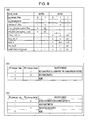
- FIG. 8 is a diagram for explaining objects to merge in the PT information decoder 13, in which FIG. 8(a) is a diagram illustrating relationships between the merge flag as well as the PU merge level flag, and objects to decode, and FIGS. 8(b) and 8(c) are diagrams illustrating relationships between the merge flag as well as the PU merge level flag, and objects to merge.
- the merge flag MRG_PU (pu_merge_flag) is decoded. Subsequently, if the value of the merge flag MRG_PU is "1", the PU merge inference flag (pu_merge_left_flag) and the PU merge level flag (pu_merge_level) are decoded (st704).
- the PT information decoder 13 decodes or infers the intra prediction mode (intra_mode) (st705).
- the PT information decoder 13 decodes or infers the motion vector residual MVD (mv_defference()) and the reference image RI (ref_pictre()) (st707), and ends the process.
- FIG. 8(a) the flags that may be decoded or inferred will be described with reference to FIG. 8(a) .
- "o" indicates that an object is decoded
- "inf.” indicates that an inferred value is used
- "def.” indicates that a default value is used
- "-" indicates that an object is unnecessary, respectively.
- the configuration may be like that illustrated in FIG. 8(c) , such that in the case where the merge level is "2", “motion information" and “transform coefficients” become the objects to merge, whereas in the case where the merge level is "1”, “motion information” becomes the object to merge, and in the case where the merge level is "0”, "transform coefficients" become the object to merge.
- the TT information decoder 14 takes the values of the merge flag MRG_TU and the TU merge inference flag to be the values of the merge flag MRG_CU and the CU merge inference flag. Also, if the prediction type information PType is inter prediction, the value of the TU merge level flag is taken to be the same as the value of the CU merge level flag (st901).
- the merge flag MRG_TU (tu_merge_flag) is decoded. Subsequently, if the value of the merge flag MRG_TU is "1", the TU merge inference flag (tu_merge_left_flag) and the TU merge level flag (tu_merge_level) are decoded (st902).
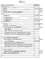
- the TT information decoder 14 decodes the transform type TTType (transform_type) (st903), and the process is divided into the case of CABAC (st904) and the case of LCEC (st905), depending on the coding mode information.
- FIG. 10(a) illustrates a syntax table for the case in which the coding mode information indicates CABAC.
- the TT information decoder 14 decodes transform coefficient presence information CV (no_resudual_data_flag) indicating whether or not transform coefficients are provided for each spatial domain (st1001).
- the transform size TTS is decoded or inferred (st1002), and in addition, the presence indicator CBP for transform coefficients in the spatial domain and the presence indicator CTC for transform coefficients in the frequency domain are decoded or inferred (st1003).
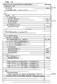
- FIG. 11 illustrates a syntax table for the case in which the coding mode information indicates LCEC.
- the TT information decoder 14 decodes transform coefficient presence information LC (cbp_yuv_root) indicating whether or not transform coefficients are provided for each luma and chroma component (st1101). Subsequently, the presence indicator CBP for transform coefficients in the spatial domain is decoded or inferred (st1102), and the presence indicator CTC for transform coefficients in the frequency domain is decoded or inferred (st1103).
- the five objects split_transform_flag, tu_merge_left_flag, cbp_luma, coded_block_flag_luma, and transform_coeff are decoded, while the three objects transform_type, cbp_cb/cr, and coded_block_flag_cb/cr are inferred.
- the one object tu_merge_left_flag is decoded, the six objects split_transform_flag, transform_type, cbp_luma, coded_block_flag_luma, cbp_cb/cr, and coded_block_flag_cb/cr are inferred, while transform_coeff takes a default value.
- the skip flag and skip level versus the objects to skip may be determined as illustrated in FIG. 12(b) . Namely, in the case where the skip flag is "1" and the skip level is "2", the objects to skip may be taken to be the transform coefficients (all coefficients), whereas in the case where the skip flag is "1" and the skip level is "1", the objects to skip may be taken to be the transform coefficients (non-DC components), and in the case where the skip flag is "1" and the skip level is "0", the objects to skip may be taken to be the transform coefficients (high-frequency components).
- the CU image generator 15 generates a CU image using the CU decoding information #23 input from the CU information decoder 12, and PT decoding information #31 input from the PT information decoder 13, and the TT decoding information #41 input from the TT information decoder 14.
- the generated CU decoded image #51 is then output to the TBLK image generator 16.
- a prediction residual is generated on the basis of the transform size TTS and the transform coefficients included in the TT decoding information #41. Lastly, the generated predicted image and prediction residual are added together to generate a CU decoded image #51.
- the TBLK image generator 16 uses the CU decoded image #51 input from the CU image generator 15 to generate and output a decoded image #2.
- the decoded image #2 is recorded in the frame memory 21.
- decoded images corresponding to all TBLKs decoded prior to that target TBLK are recorded in the frame memory 21.
- FIG. 13 is a diagram for explaining the case of merging in units of CUs (the CU information CU and the PT information PTI). Also, FIG. 14 is a diagram for explaining the case of merging in units of TUs (the TTI information TTI).
- the merge flag MRG_CU (cu_merge_flag) is "1” and the CU merge inference flag (cu_merge_left_gflag) is "1"
- the value of the PU split information SP_PU (intra_split_flag) is inferred to be "1” from the CU adjacent to the left.
- the intra prediction mode IPM is likewise inferred to be "horizontal prediction” from the CU adjacent to the left.
- the PUs become a quadtree subdivision of the CU, similarly to the CU 1302.
- edge-based prediction refers to prediction that utilizes an edge direction inferred on the basis of pixel values in the decoded image of a neighboring area and the intra prediction mode
- planar prediction refers to prediction that utilizes interpolation based on inferred values for the lower-right pixel value within a PU and pixel values in the decoded image of a PU adjacent area.
- the tree block split information SP_TBLK split_coding_unit_flag
- SP_PU may also be an object to merge.
- FIG. 14 illustrates two CUs: a CU 1401 and a CU 1401'. Additionally, in the CU 1401, assume that the merge flag MRG_TU (tu_merge_flag) is "0", the transform size TTS is "Y”, the presence indicator CBP for transform coefficients in the spatial domain is "Y”, and the transform coefficients TTC are "all frequency components".
- the value of the merge flag MRG_TU (tu_merge_flag) is "1" and the value of the TU merge inference flag (tu_merge_left_flag) is "1"
- the value is inferred from the CU adjacent to the left.
- the transform size TTS and the presence indicator CBP for transform coefficients in the spatial domain are copied from the CU 1401 and become the same values.
- transform coefficients TTC all may be copied, or only some may be copied. For example, in cases such as where non-zero transform coefficients exist for pixels 1420a to 1420d in a PU 1411 belonging to the CU 1401, for a PU 1411' belonging to the CU 1401' to which those transform coefficients are to be copied, transform coefficients may be copied only into the area 1421 that includes the non-zero transform coefficients.
- transform information such as the transform size TTS (split_transform_type) and the transform type TTType (transform_type). Since transform information is spatially correlated, the above configuration enables a high-quality decoded image #2 to be decoded while reducing the bit rate of the encoded data #1.
- the video image encoding device 2 is a device that generates and outputs an encoded image #1 by encoding an input image #100.
- the video image encoding device 2 is a video image encoding device, parts of which use technology implemented in the H.264/MPEG-4 AVC standard, technology implemented in the KTA software, which is a jointly developed codec by the Video Coding Experts Group (VCEG), technology implemented in the Test Model under Consideration (TMuC) software, as well as the scheme implemented in the successor codec HEVC WD1.
- VCEG Video Coding Experts Group
- TMC Test Model under Consideration
- the CU to reference in the case of merging is taken to be a CU adjacent on the left side of the target CU
- the CU to reference is not limited thereto.
- the CU to reference may also be a CU adjacent on the top side of the target CU, or a CU existing nearby, but not adjacent to the target CU.
- a CU belonging to a previous frame is acceptable.
- the layer may be changed to encode information, it is possible to reduce the side information, that is, the information excepting the prediction residual.
- relV(k) is set to 0.
- the function relV(k) indicates the strength of the relevance of syntax between vertically neighboring blocks.
- relH(k) is set 0.
- the function relH(k) indicates the strength of the relevance of syntax between horizontally neighboring blocks.
- cnt(k) is set to 0.
- merge_k_flag (relV(k) / cnt(k) > Th(k)
- the position of the PU to reference is taken to be above if relV(k)>relH(k), and to the left otherwise (information indicating the position of an object to merge is not decoded). Also, a corresponding flag is decoded in the case where the condition is not satisfied.
- objects to merge may be sent in a header. This may encompass, for example, explicitly transmitting objects, selecting from default combinations, and transmitting only the objects for a specific level.
- Merge levels may also be transmitted in the case where the size of a target CU, PU, or TU is greater than a default size.
- the presence indicator for transform coefficients in the frequency domain (hereinafter designated the CTC) is taken to be a set of flags indicating whether or not transform coefficients are present in each partial frequency domain obtained by splitting the frequency domain as illustrated in FIG. 10(b) .
- FIG. 16 is an explanatory diagram for expressing the presence indicator CTC for transform coefficients in the frequency domain, in which FIG. 16(a) is a diagram illustrating the case of expressing the CTC by splitting the frequency domain into non-square domains, FIG. 16(b) is a diagram illustrating the case of expressing the CTC by using a parameter, and FIG. 16(c) is a diagram illustrating the case of expressing the CTC by using a scan order.
- Flags indicating whether or not transform coefficients are present in each domain obtained by splitting the frequency domain into non-square partial frequency domains may be set, and information collecting these flags may be treated as the CTC.
- the frequency domain is split into a DC portion, a horizontal edge portion (a domain in which the horizontal frequency component is large while the vertical frequency component is small), a vertical edge portion (a domain in which the vertical frequency component is large while the horizontal frequency component is small), and a high-frequency component (a domain in which the vertical and horizontal frequency components are both large).
- Presence indicators for transform coefficients in the respective domains are associated with the flags f DC , f H , f V , and f HF , which are then taken to be the CTC.
- inference in a merge process may be realized by copying a flag indicating whether or not transform coefficients are present in a corresponding partial frequency domain in the TU being referenced. Also, by not restricting the split frequency domains to square shapes, it becomes possible to more flexibly set the transform coefficient presence indicator flags.
- a parameter k is defined, with the value of k set in the CTC such that transform coefficients are contained within a partial frequency domain whose horizontal frequency component is between 0 and k inclusive, and whose vertical frequency component is between 0 and k inclusive.
- Int() is a function that retrieves the integer portion of an argument.
- last_coeff a target TU in a merge process
- m' the value of last_coeff in the reference TU
- ⁇ is a value indicating change in the position of last_coeff, and is set to the width of the TU, for example.
- b is the number of pixels included in the TU.
- the transmitting device A may be additionally equipped with a camera A4 that captures a video image, a recording medium A5 onto which a video image is recorded, an input terminal A6 for externally inputting a video image, and an image processor A7 that generates or processes an image.
- FIG. 17(a) exemplifies a transmitting device A equipped with all of the above, some may also be omitted.
- the recording medium A5 may be a medium recording an unencoded video image, or a medium recording a video image encoded with a coding scheme for recording that differs from the coding scheme for transmission.
- a decoder (not illustrated) that decodes encoded data read out from the recording medium A5 in accordance with the coding scheme for recording may be interposed between the recording medium A5 and the encoder A1.
- the recording medium B5 may be a medium for recording an unencoded video image, or a medium for recording a video image encoded with a coding scheme for recording that differs from the coding scheme for transmission.
- an encoder (not illustrated) that encodes a video image acquired from the decoder B3 in accordance with the coding scheme for recording may be interposed between the decoder B3 and the recording medium B5.
- the transmission medium via which a modulated signal is transmitted may be wireless or wired.
- the transmission format by which a modulated signal is transmitted may be broadcasting (herein indicating a transmission format in which a recipient is not specified in advance) or communication (herein indicating a transmission format in which a recipient is specified in advance).
- the transmission of a modulated signal may be realized by any of wireless transmission, wired transmission, wireless communication, and wired communication.
- a digital terrestrial broadcasting station (such as a broadcasting facility)/receiving station (such as a television receiver) is an example of a transmitting device A/receiving device B that transmits or receives a modulated signal by wireless broadcasting.
- a cable television broadcasting station (such as a broadcasting facility)/receiving station (such as a television receiver) is an example of a transmitting device A/receiving device B that transmits or receives a modulated signal by wired broadcasting.
- a server such as a workstation
- client such as a television receiver, personal computer, or smartphone
- a service such as a video on demand (VOD) service or video sharing service using the Internet
- VOD video on demand
- a transmitting device A/receiving device B that transmits or receives a modulated signal by communication (ordinarily, either a wireless or wired medium is used as the transmission medium in a LAN, while a wired medium is used as the transmission medium in a WAN).
- the term personal computer encompasses desktop PCs, laptop PCs, and tablet PCs.
- smartphone encompasses multifunction mobile phone devices.
- a client of a video sharing service includes functions for decoding encoded data downloaded from a server and displaying the decoded data on a display, and additionally includes functions for encoding a video image captured with a camera and uploading the encoded data to a server.
- a client of a video sharing service functions as both the transmitting device A and the receiving device B.
- the recording medium M may be (1) of a type that is built into the recording device C, such as a hard disk drive (HDD) or a solid-state drive (SSD), (2) of a type that is connected to the recording device C, such as an SD memory card or Universal Serial Bus (USB) flash memory, or (3) loaded into a drive device (not illustrated) built into the recording device C, such as a Digital Versatile Disc (DVD) or Blu-ray Disc (BD; registered trademark).
- HDD hard disk drive
- SSD solid-state drive
- USB Universal Serial Bus
- the receiver C5 may be a receiver that receives an unencoded video image, or a receiver that receives encoded data that has been encoded with a coding scheme for transmission that differs from the coding scheme for recording.
- a transmission decoder (not illustrated) that decodes encoded data that has been encoded with the coding scheme for transmission may be interposed between the receiver C5 and the encoder C1.
- Such a recording device C are, for example, a DVD recorder, a BD recorder, or a hard disk (HD) recorder (in this case, the input terminal C4 or the receiver C5 becomes the primary source for supplying video images). Also, devices such as a camcorder (in this case, the camera C3 becomes the primary source for supplying video images), a personal computer (in this case, the receiver C5 or the image processor C6 becomes the primary source for supplying video images), a smartphone (in this case, the camera C3 or the receiver C5 becomes the primary source for supplying video images) are also examples of such a recording device C.
- a camcorder in this case, the camera C3 becomes the primary source for supplying video images
- a personal computer in this case, the receiver C5 or the image processor C6 becomes the primary source for supplying video images
- a smartphone in this case, the camera C3 or the receiver C5 becomes the primary source for supplying video images
- FIG. 18(b) is a block diagram illustrating a configuration of a playback device D equipped with the video image decoding device 1 discussed earlier.
- the playback device D is equipped with a reader D1 that reads out encoded data written to a recording medium M, and a decoder D2 that obtains a video image by decoding encoded data read out by the reader D1.
- the video image decoding device 1 discussed earlier is used as the decoder D2.
- the recording medium M may be (1) of a type that is built into the playback device D, such as an HDD or SSD, (2) of a type that is connected to the playback device D, such as an SD memory card or USB flash memory, or (3) loaded into a drive device (not illustrated) built into the playback device D, such as a DVD or BD.
- the playback device D may be additionally equipped with a display D3 that displays a video image, an output terminal D4 for externally outputting a video image, and a transmitter D5 that transmits a video image.
- FIG. 18(b) exemplifies a playback device D equipped with all of the above, some may also be omitted.
- the transmitter D5 may be a transmitter that transmits an unencoded video image, or a transmitter that transmits encoded data that has been encoded with a coding scheme for transmission that differs from the coding scheme for recording.
- an encoder (not illustrated) that encodes a video image with the coding scheme for transmission may be interposed between the decoder D2 and the transmitter D5.
- Such a playback device D are, for example, a DVD player, a BD player, or an HDD player (in this case, the output terminal D4 connected to a television receiver or the like becomes the primary destination to supply with video images).
- devices such as a television receiver (in this case, the display D3 becomes the primary destination to supply with video images), a desktop PC (in this case, the output terminal D4 or the transmitter D5 becomes the primary destination to supply with video images), a laptop or tablet PC (in this case, the display D3 or the transmitter D5 becomes the primary destination to supply with video images), a smartphone (in this case, the display D3 or the transmitter D5 becomes the primary destination to supply with video images), and digital signage (also referred to as electronic signs or electronic billboards; the display D3 or the transmitter D5 becomes the primary destination to supply with video images) are also examples of such a playback device D.
- each block of the video image decoding device 1 and the video image encoding device 2 may be realized in hardware by logical circuits formed on an integrated circuit (IC chip), but may also be realized in software using a central processing unit (CPU).
- IC chip integrated circuit
- CPU central processing unit
- the video image decoding device 1 and the video image encoding device 2 are equipped with a CPU that executes the commands of a control program that realizes respective functions, read-only memory (ROM) that stores the above program, random access memory (RAM) into which the above program is loaded, a storage device (recording medium) such as memory that stores the above program and various data, and the like.
- ROM read-only memory
- RAM random access memory
- storage device recording medium
- the object of the present invention is then achievable by supplying the above video image decoding device 1 and the video image encoding device 2 with a recording medium upon which is recorded, in computer-readable form, program code (a program in executable format, an intermediate code program, or source program) of the control program of the video image decoding device 1 and the video image encoding device 2 that is software realizing the functions discussed above, and by having that computer (or CPU or microprocessor unit (MPU)) read out and execute program code recorded on the recording medium.
- program code a program in executable format, an intermediate code program, or source program
- a tape-based type such as magnetic tape or a cassette tape, a disk-based tape such as a floppy (registered trademark) disk/hard disk, and also including optical discs such as a Compact Disc - Read-Only Memory (CD-ROM)/magneto-optical (MO)/MiniDisc (MD)/Digital Versatile Disc (DVD)/CD-Recordable (CD-R) disc, a card-based type such as an IC card (including memory cards)/optical memory card, a semiconductor memory-based type such as mask ROM/erasable programmable read-only memory (EPROM)/electrically erasable and programmable read-only memory (EEPROM)/flash ROM, a logical circuit-based type such as a programmable logic device (PLD) or field-programmable gate array (FPGA), or the like may be used.
- CD-ROM Compact Disc - Read-Only Memory
- MO magneticto-optical
- MD Magnetic Versatile Disc
- the video image decoding device 1 and the video image encoding device 2 may be configured to be connectable to a communication network, such that the above program code is supplied via a communication network.
- the communication network is not particularly limited, insofar as program code is able to be transmitted.
- a network such as the Internet, an intranet, an extranet, a local area network (LAN), an Integrated Services Digital Network (ISDN), a value-added network (VAN), a community antenna television (CATV) communication network, a virtual private network, a telephone line network, a mobile communication network, or a satellite communication network is usable.
- the transmission medium constituting the communication network is not limited to a specific configuration or type, insofar as program code is able to be transmitted.
- decoding may be conducted by transmitting only merge/skip information, without transmitting information indicating whether or not non-zero transform coefficients are included in a component, excepting a direct current component, of frequency components in the quantized transform coefficients.
- decoding may be conducted by transmitting only merge/skip information, without transmitting information indicating whether or not non-zero transform coefficients are included in a high-frequency component of frequency components in the quantized transform coefficients.
- the bit rate of encoded data may be further reduced.
- the units by which the predicted image is generated, transformed, and encoded may respectively differ
- the encoded data may include data per each of the units
- the merge/skip information and the merge/skip level information may be included in different units from among the units.
- the inferring means may also set a reference transform unit to reference in order to infer information to be merged/skipped, on the basis of a decoding result previously decoded by the decoding means.
- the inferring means sets a reference transform unit using a previous decoding result. Additionally, there is a high probability that a previous decoding result is similar to the current decoding. Accordingly, a reference transform unit may be suitably set.
- a data structure of encoded data according to the present invention is a data structure of encoded data that includes encoded and quantized transform coefficients in which a prediction residual obtained by subtracting a predicted image from an original image is transformed and quantized per a transform unit, and the quantized transform coefficients are encoded.
- the data structure includes merge/skip information that merges or skips presence information indicating whether or not frequency-domain transform coefficients are included in the quantized transform coefficients.
- encoded data includes only merge/skip information, without including information indicating whether or not frequency-domain transform coefficients are present.
Landscapes
- Engineering & Computer Science (AREA)
- Multimedia (AREA)
- Signal Processing (AREA)
- Physics & Mathematics (AREA)
- Discrete Mathematics (AREA)
- General Physics & Mathematics (AREA)
- Compression Or Coding Systems Of Tv Signals (AREA)
Priority Applications (1)
| Application Number | Priority Date | Filing Date | Title |
|---|---|---|---|
| EP18185768.1A EP3413564A1 (fr) | 2011-03-10 | 2012-03-07 | Dispositif de décodage d'images |
Applications Claiming Priority (2)
| Application Number | Priority Date | Filing Date | Title |
|---|---|---|---|
| JP2011053611 | 2011-03-10 | ||
| PCT/JP2012/055805 WO2012121284A1 (fr) | 2011-03-10 | 2012-03-07 | Appareil de décodage d'image, appareil de codage d'image et structure de données codées |
Related Child Applications (2)
| Application Number | Title | Priority Date | Filing Date |
|---|---|---|---|
| EP18185768.1A Division EP3413564A1 (fr) | 2011-03-10 | 2012-03-07 | Dispositif de décodage d'images |
| EP18185768.1A Division-Into EP3413564A1 (fr) | 2011-03-10 | 2012-03-07 | Dispositif de décodage d'images |
Publications (3)
| Publication Number | Publication Date |
|---|---|
| EP2685718A1 true EP2685718A1 (fr) | 2014-01-15 |
| EP2685718A4 EP2685718A4 (fr) | 2015-03-11 |
| EP2685718B1 EP2685718B1 (fr) | 2018-08-29 |
Family
ID=46798240
Family Applications (2)
| Application Number | Title | Priority Date | Filing Date |
|---|---|---|---|
| EP18185768.1A Withdrawn EP3413564A1 (fr) | 2011-03-10 | 2012-03-07 | Dispositif de décodage d'images |
| EP12754367.6A Active EP2685718B1 (fr) | 2011-03-10 | 2012-03-07 | Appareil de décodage d'image |
Family Applications Before (1)
| Application Number | Title | Priority Date | Filing Date |
|---|---|---|---|
| EP18185768.1A Withdrawn EP3413564A1 (fr) | 2011-03-10 | 2012-03-07 | Dispositif de décodage d'images |
Country Status (5)
| Country | Link |
|---|---|
| US (2) | US10148974B2 (fr) |
| EP (2) | EP3413564A1 (fr) |
| JP (2) | JPWO2012121284A1 (fr) |
| CN (5) | CN107105259B (fr) |
| WO (1) | WO2012121284A1 (fr) |
Cited By (1)
| Publication number | Priority date | Publication date | Assignee | Title |
|---|---|---|---|---|
| US20240414348A1 (en) * | 2021-09-22 | 2024-12-12 | Sharp Kabushiki Kaisha | Systems and methods for compression of feature data using joint coding in coding of multi-dimensional data |
Families Citing this family (31)
| Publication number | Priority date | Publication date | Assignee | Title |
|---|---|---|---|---|
| CN107105259B (zh) * | 2011-03-10 | 2021-12-28 | 夏普株式会社 | 图像解码装置及方法、以及记录介质 |
| EP3614670B1 (fr) * | 2011-12-15 | 2021-02-03 | Tagivan Ii Llc | Signalisation de drapeaux de blocs codés (cbf) de luminance-chrominance en codage vidéo |
| AU2012200319B2 (en) * | 2012-01-19 | 2015-11-26 | Canon Kabushiki Kaisha | Method, apparatus and system for encoding and decoding the significance map for residual coefficients of a transform unit |
| WO2013145021A1 (fr) * | 2012-03-30 | 2013-10-03 | 株式会社日立製作所 | Procédé de décodage d'images et appareil de décodage d'images |
| US9432390B2 (en) * | 2013-12-31 | 2016-08-30 | Prometheus Security Group Global, Inc. | Scene identification system and methods |
| WO2016178485A1 (fr) * | 2015-05-05 | 2016-11-10 | 엘지전자 주식회사 | Procédé et dispositif de traitement d'unité de codage dans un système de codage d'image |
| US9942548B2 (en) * | 2016-02-16 | 2018-04-10 | Google Llc | Entropy coding transform partitioning information |
| CN109479131B (zh) * | 2016-06-24 | 2023-09-01 | 世宗大学校产学协力团 | 视频信号处理方法及装置 |
| KR20250004171A (ko) | 2016-10-04 | 2025-01-07 | 주식회사 비원영상기술연구소 | 영상 데이터 부호화/복호화 방법 및 장치 |
| US20190238888A1 (en) * | 2017-07-17 | 2019-08-01 | Ki Baek Kim | Image data encoding/decoding method and apparatus |
| WO2018174617A1 (fr) | 2017-03-22 | 2018-09-27 | 한국전자통신연구원 | Procédé de prédiction basé sur une forme de bloc et dispositif associé |
| WO2018199001A1 (fr) * | 2017-04-28 | 2018-11-01 | シャープ株式会社 | Dispositif de décodage d'image et dispositif de codage d'image |
| CN115002459B (zh) | 2018-01-05 | 2025-09-09 | Sk电信有限公司 | 视频解码设备、视频编码设备和非暂时性计算机可读介质 |
| KR102524628B1 (ko) | 2018-01-05 | 2023-04-21 | 에스케이텔레콤 주식회사 | 영상을 부호화 또는 복호화하는 방법 및 장치 |
| US11445187B2 (en) * | 2018-02-28 | 2022-09-13 | Sharp Kabushiki Kaisha | Systems and methods for partitioning regions of a picture for video coding using different coding unit sizes |
| US10645396B2 (en) * | 2018-06-04 | 2020-05-05 | Tencent America LLC | Method and apparatus for implicit transform splitting |
| CN119893093A (zh) * | 2018-07-13 | 2025-04-25 | 韩国电子通信研究院 | 对图像进行编码/解码的方法以及记录介质 |
| CN117156129A (zh) * | 2018-10-23 | 2023-12-01 | 韦勒斯标准与技术协会公司 | 通过使用基于子块的运动补偿处理视频信号的方法和设备 |
| JP2022016726A (ja) | 2018-11-16 | 2022-01-25 | ソニーグループ株式会社 | 画像処理装置および方法 |
| EP3881546A4 (fr) | 2018-12-04 | 2022-01-26 | Huawei Technologies Co., Ltd. | Codeur vidéo, décodeur vidéo, et procédé correspondant |
| US11234007B2 (en) | 2019-01-05 | 2022-01-25 | Tencent America LLC | Method and apparatus for video coding |
| CN113632493B (zh) * | 2019-03-13 | 2024-07-12 | 北京字节跳动网络技术有限公司 | 变换跳过模式中的子块变换 |
| CN120881276A (zh) * | 2019-05-30 | 2025-10-31 | 夏普株式会社 | 图像解码装置 |
| JP6912522B2 (ja) * | 2019-06-24 | 2021-08-04 | Kddi株式会社 | 画像復号装置、画像復号方法及びプログラム |
| WO2020261313A1 (fr) * | 2019-06-24 | 2020-12-30 | 日本電信電話株式会社 | Procédé de codage d'image et procédé de décodage d'image |
| JP7189854B2 (ja) * | 2019-09-19 | 2022-12-14 | Kddi株式会社 | 画像復号装置、画像復号方法及びプログラム |
| TW202537285A (zh) * | 2019-09-23 | 2025-09-16 | 法商內數位Ce專利控股公司 | 編碼樹分割的方法與設備及其儲存媒體 |
| CN111160348A (zh) * | 2019-11-20 | 2020-05-15 | 中国科学院深圳先进技术研究院 | 自然场景的文本识别方法、存储装置和计算机设备 |
| US11706425B2 (en) * | 2020-01-08 | 2023-07-18 | Qualcomm Incorporated | Multiple transform set signaling for video coding |
| JP7469904B2 (ja) * | 2020-02-21 | 2024-04-17 | シャープ株式会社 | 画像復号装置、画像符号化装置、画像復号方法及び画像符号化方法 |
| WO2025149324A1 (fr) * | 2024-01-08 | 2025-07-17 | Interdigital Ce Patent Holdings, Sas | Héritage d'informations de transformée |
Family Cites Families (31)
| Publication number | Priority date | Publication date | Assignee | Title |
|---|---|---|---|---|
| JP4025570B2 (ja) * | 2002-04-03 | 2007-12-19 | 日本電信電話株式会社 | 動画像符号化方法、動画像復号方法、動画像符号化装置、動画像復号装置、動画像符号化プログラム、動画像復号プログラム、動画像符号化プログラムを記録した記録媒体、動画像復号プログラムを記録した記録媒体 |
| US7630440B2 (en) * | 2003-05-28 | 2009-12-08 | Broadcom Corporation | Context adaptive binary arithmetic code decoding engine |
| CN100344163C (zh) * | 2004-06-16 | 2007-10-17 | 华为技术有限公司 | 视频编解码处理方法 |
| WO2006068435A2 (fr) * | 2004-12-22 | 2006-06-29 | Lg Electronics Inc. | Appareil et procede de decodage de code de canal |
| US20090028239A1 (en) * | 2005-05-03 | 2009-01-29 | Bernhard Schuur | Moving picture encoding method, moving picture decoding method and apparatuses using the methods |
| KR100809298B1 (ko) * | 2006-06-22 | 2008-03-04 | 삼성전자주식회사 | 플래그 인코딩 방법, 플래그 디코딩 방법, 및 상기 방법을이용한 장치 |
| CA2675891C (fr) * | 2007-01-18 | 2013-04-16 | Fraunhofer-Gesellschaft Zur Foerderung Der Angewandten Forschung E.V. | Flux de donnees video a qualite echelonnable |
| EP2140684B1 (fr) * | 2007-04-12 | 2018-08-15 | Thomson Licensing DTV | Procédé et appareil de fusion selon le contexte pour des modes skip/direct pour un codage et un décodage vidéo |
| KR101431545B1 (ko) * | 2008-03-17 | 2014-08-20 | 삼성전자주식회사 | 영상의 부호화, 복호화 방법 및 장치 |
| US8897359B2 (en) * | 2008-06-03 | 2014-11-25 | Microsoft Corporation | Adaptive quantization for enhancement layer video coding |
| KR20090129926A (ko) * | 2008-06-13 | 2009-12-17 | 삼성전자주식회사 | 영상 부호화 방법 및 그 장치, 영상 복호화 방법 및 그 장치 |
| WO2010018992A2 (fr) | 2008-08-12 | 2010-02-18 | Lg Electronics Inc. | Procédé de traitement d'un signal vidéo |
| US8634456B2 (en) * | 2008-10-03 | 2014-01-21 | Qualcomm Incorporated | Video coding with large macroblocks |
| SG10201402451XA (en) * | 2009-05-29 | 2014-07-30 | Mitsubishi Electric Corp | Image encoding device, image decoding device, image encoding method, and image decoding method |
| US9635368B2 (en) | 2009-06-07 | 2017-04-25 | Lg Electronics Inc. | Method and apparatus for decoding a video signal |
| US9100648B2 (en) * | 2009-06-07 | 2015-08-04 | Lg Electronics Inc. | Method and apparatus for decoding a video signal |
| US8588296B2 (en) * | 2009-07-02 | 2013-11-19 | Dialogic Corporation | Bitrate control algorithm for video transcoding systems |
| CN101959064B (zh) * | 2009-07-14 | 2012-05-30 | 炬力集成电路设计有限公司 | 一种视频解码方法及装置 |
| KR101483750B1 (ko) * | 2009-07-24 | 2015-01-19 | 삼성전자주식회사 | 영상의 부호화 방법 및 장치, 영상 복호화 방법 및 장치 |
| KR20110014000A (ko) * | 2009-08-04 | 2011-02-10 | 광운대학교 산학협력단 | 영상 데이터의 디블록킹 필터링 장치 및 방법과 이를 이용한 영상 복호화 장치 및 방법 |
| KR101456498B1 (ko) * | 2009-08-14 | 2014-10-31 | 삼성전자주식회사 | 계층적 부호화 단위의 스캔 순서를 고려한 비디오 부호화 방법 및 장치, 비디오 복호화 방법 및 장치 |
| KR101457894B1 (ko) * | 2009-10-28 | 2014-11-05 | 삼성전자주식회사 | 영상 부호화 방법 및 장치, 복호화 방법 및 장치 |
| US8780978B2 (en) * | 2009-11-04 | 2014-07-15 | Qualcomm Incorporated | Controlling video encoding using audio information |
| US20110292997A1 (en) * | 2009-11-06 | 2011-12-01 | Qualcomm Incorporated | Control of video encoding based on image capture parameters |
| US10178406B2 (en) * | 2009-11-06 | 2019-01-08 | Qualcomm Incorporated | Control of video encoding based on one or more video capture parameters |
| WO2011121715A1 (fr) * | 2010-03-30 | 2011-10-06 | 株式会社 東芝 | Procédé de décodage d'image |
| US20110249742A1 (en) * | 2010-04-07 | 2011-10-13 | Apple Inc. | Coupled video pre-processor and codec including reference picture filter that minimizes coding expense during pre-processing mode transitions |
| US8665959B2 (en) * | 2010-04-12 | 2014-03-04 | Qualcomm Incorporated | Block and partition signaling techniques for video coding |
| JP5798556B2 (ja) * | 2010-07-15 | 2015-10-21 | シャープ株式会社 | 復号装置、符号化装置 |
| US20120189052A1 (en) * | 2011-01-24 | 2012-07-26 | Qualcomm Incorporated | Signaling quantization parameter changes for coded units in high efficiency video coding (hevc) |
| CN107105259B (zh) | 2011-03-10 | 2021-12-28 | 夏普株式会社 | 图像解码装置及方法、以及记录介质 |
-
2012
- 2012-03-07 CN CN201611226083.1A patent/CN107105259B/zh active Active
- 2012-03-07 EP EP18185768.1A patent/EP3413564A1/fr not_active Withdrawn
- 2012-03-07 CN CN201611225881.2A patent/CN107087178B/zh active Active
- 2012-03-07 CN CN201611226198.0A patent/CN107071439B/zh active Active
- 2012-03-07 WO PCT/JP2012/055805 patent/WO2012121284A1/fr not_active Ceased
- 2012-03-07 CN CN201280012467.7A patent/CN103460694B/zh active Active
- 2012-03-07 EP EP12754367.6A patent/EP2685718B1/fr active Active
- 2012-03-07 US US14/003,686 patent/US10148974B2/en active Active
- 2012-03-07 JP JP2013503573A patent/JPWO2012121284A1/ja active Pending
- 2012-03-07 CN CN201611227733.4A patent/CN107087179B/zh active Active
-
2017
- 2017-04-20 JP JP2017084008A patent/JP6483183B2/ja active Active
-
2018
- 2018-06-07 US US16/002,224 patent/US10547861B2/en active Active
Cited By (1)
| Publication number | Priority date | Publication date | Assignee | Title |
|---|---|---|---|---|
| US20240414348A1 (en) * | 2021-09-22 | 2024-12-12 | Sharp Kabushiki Kaisha | Systems and methods for compression of feature data using joint coding in coding of multi-dimensional data |
Also Published As
| Publication number | Publication date |
|---|---|
| CN107087179B (zh) | 2021-04-27 |
| US10547861B2 (en) | 2020-01-28 |
| EP3413564A1 (fr) | 2018-12-12 |
| CN107105259A (zh) | 2017-08-29 |
| CN103460694A (zh) | 2013-12-18 |
| US20130343455A1 (en) | 2013-12-26 |
| CN107087179A (zh) | 2017-08-22 |
| CN107087178B (zh) | 2021-12-28 |
| US10148974B2 (en) | 2018-12-04 |
| CN107087178A (zh) | 2017-08-22 |
| JPWO2012121284A1 (ja) | 2014-07-17 |
| EP2685718B1 (fr) | 2018-08-29 |
| WO2012121284A1 (fr) | 2012-09-13 |
| HK1191484A1 (zh) | 2014-07-25 |
| JP2017147750A (ja) | 2017-08-24 |
| CN107071439A (zh) | 2017-08-18 |
| CN107105259B (zh) | 2021-12-28 |
| JP6483183B2 (ja) | 2019-03-13 |
| CN107071439B (zh) | 2021-12-28 |
| CN103460694B (zh) | 2017-02-15 |
| EP2685718A4 (fr) | 2015-03-11 |
| US20180295360A1 (en) | 2018-10-11 |
Similar Documents
| Publication | Publication Date | Title |
|---|---|---|
| EP2685718B1 (fr) | Appareil de décodage d'image | |
| US12477139B2 (en) | Image decoding device and image coding device | |
| JP2022051736A (ja) | 算術復号装置 | |
| KR101768401B1 (ko) | 화상 복호 장치 | |
| US20160286235A1 (en) | Image Decoding Apparatus, Image Coding Apparatus, and Coded Data Transformation Apparatus | |
| US10136161B2 (en) | DMM prediction section, image decoding device, and image coding device | |
| JP2013251827A (ja) | 画像フィルタ装置、画像復号装置、画像符号化装置、およびデータ構造 | |
| WO2012147947A1 (fr) | Appareil de décodage d'image et appareil de codage d'image | |
| JP2016076904A (ja) | Dcオフセット情報復号装置、画像復号装置、およびdcオフセット情報符号化装置。 | |
| HK1191484B (en) | Image decoding apparatus, image encoding apparatus, and data structure of encoded data |
Legal Events
| Date | Code | Title | Description |
|---|---|---|---|
| PUAI | Public reference made under article 153(3) epc to a published international application that has entered the european phase |
Free format text: ORIGINAL CODE: 0009012 |
|
| 17P | Request for examination filed |
Effective date: 20130910 |
|
| AK | Designated contracting states |
Kind code of ref document: A1 Designated state(s): AL AT BE BG CH CY CZ DE DK EE ES FI FR GB GR HR HU IE IS IT LI LT LU LV MC MK MT NL NO PL PT RO RS SE SI SK SM TR |
|
| DAX | Request for extension of the european patent (deleted) | ||
| A4 | Supplementary search report drawn up and despatched |
Effective date: 20150209 |
|
| RIC1 | Information provided on ipc code assigned before grant |
Ipc: H04N 19/122 20140101AFI20150203BHEP |
|
| 17Q | First examination report despatched |
Effective date: 20151008 |
|
| REG | Reference to a national code |
Ref country code: DE Ref legal event code: R079 Ref document number: 602012050406 Country of ref document: DE Free format text: PREVIOUS MAIN CLASS: H04N0007320000 Ipc: H04N0019700000 |
|
| GRAP | Despatch of communication of intention to grant a patent |
Free format text: ORIGINAL CODE: EPIDOSNIGR1 |
|
| STAA | Information on the status of an ep patent application or granted ep patent |
Free format text: STATUS: GRANT OF PATENT IS INTENDED |
|
| RIC1 | Information provided on ipc code assigned before grant |
Ipc: H04N 19/46 20140101ALI20180306BHEP Ipc: H04N 19/70 20140101AFI20180306BHEP |
|
| INTG | Intention to grant announced |
Effective date: 20180328 |
|
| GRAS | Grant fee paid |
Free format text: ORIGINAL CODE: EPIDOSNIGR3 |
|
| GRAA | (expected) grant |
Free format text: ORIGINAL CODE: 0009210 |
|
| STAA | Information on the status of an ep patent application or granted ep patent |
Free format text: STATUS: THE PATENT HAS BEEN GRANTED |
|
| AK | Designated contracting states |
Kind code of ref document: B1 Designated state(s): AL AT BE BG CH CY CZ DE DK EE ES FI FR GB GR HR HU IE IS IT LI LT LU LV MC MK MT NL NO PL PT RO RS SE SI SK SM TR |
|
| REG | Reference to a national code |
Ref country code: GB Ref legal event code: FG4D |
|
| REG | Reference to a national code |
Ref country code: CH Ref legal event code: EP |
|
| REG | Reference to a national code |
Ref country code: AT Ref legal event code: REF Ref document number: 1036592 Country of ref document: AT Kind code of ref document: T Effective date: 20180915 |
|
| REG | Reference to a national code |
Ref country code: IE Ref legal event code: FG4D |
|
| REG | Reference to a national code |
Ref country code: DE Ref legal event code: R096 Ref document number: 602012050406 Country of ref document: DE |
|
| REG | Reference to a national code |
Ref country code: NL Ref legal event code: FP |
|
| REG | Reference to a national code |
Ref country code: LT Ref legal event code: MG4D |
|
| PG25 | Lapsed in a contracting state [announced via postgrant information from national office to epo] |
Ref country code: FI Free format text: LAPSE BECAUSE OF FAILURE TO SUBMIT A TRANSLATION OF THE DESCRIPTION OR TO PAY THE FEE WITHIN THE PRESCRIBED TIME-LIMIT Effective date: 20180829 Ref country code: GR Free format text: LAPSE BECAUSE OF FAILURE TO SUBMIT A TRANSLATION OF THE DESCRIPTION OR TO PAY THE FEE WITHIN THE PRESCRIBED TIME-LIMIT Effective date: 20181130 Ref country code: IS Free format text: LAPSE BECAUSE OF FAILURE TO SUBMIT A TRANSLATION OF THE DESCRIPTION OR TO PAY THE FEE WITHIN THE PRESCRIBED TIME-LIMIT Effective date: 20181229 Ref country code: BG Free format text: LAPSE BECAUSE OF FAILURE TO SUBMIT A TRANSLATION OF THE DESCRIPTION OR TO PAY THE FEE WITHIN THE PRESCRIBED TIME-LIMIT Effective date: 20181129 Ref country code: SE Free format text: LAPSE BECAUSE OF FAILURE TO SUBMIT A TRANSLATION OF THE DESCRIPTION OR TO PAY THE FEE WITHIN THE PRESCRIBED TIME-LIMIT Effective date: 20180829 Ref country code: NO Free format text: LAPSE BECAUSE OF FAILURE TO SUBMIT A TRANSLATION OF THE DESCRIPTION OR TO PAY THE FEE WITHIN THE PRESCRIBED TIME-LIMIT Effective date: 20181129 Ref country code: RS Free format text: LAPSE BECAUSE OF FAILURE TO SUBMIT A TRANSLATION OF THE DESCRIPTION OR TO PAY THE FEE WITHIN THE PRESCRIBED TIME-LIMIT Effective date: 20180829 Ref country code: LT Free format text: LAPSE BECAUSE OF FAILURE TO SUBMIT A TRANSLATION OF THE DESCRIPTION OR TO PAY THE FEE WITHIN THE PRESCRIBED TIME-LIMIT Effective date: 20180829 |
|
| REG | Reference to a national code |
Ref country code: AT Ref legal event code: MK05 Ref document number: 1036592 Country of ref document: AT Kind code of ref document: T Effective date: 20180829 |
|
| PG25 | Lapsed in a contracting state [announced via postgrant information from national office to epo] |
Ref country code: AL Free format text: LAPSE BECAUSE OF FAILURE TO SUBMIT A TRANSLATION OF THE DESCRIPTION OR TO PAY THE FEE WITHIN THE PRESCRIBED TIME-LIMIT Effective date: 20180829 Ref country code: LV Free format text: LAPSE BECAUSE OF FAILURE TO SUBMIT A TRANSLATION OF THE DESCRIPTION OR TO PAY THE FEE WITHIN THE PRESCRIBED TIME-LIMIT Effective date: 20180829 Ref country code: HR Free format text: LAPSE BECAUSE OF FAILURE TO SUBMIT A TRANSLATION OF THE DESCRIPTION OR TO PAY THE FEE WITHIN THE PRESCRIBED TIME-LIMIT Effective date: 20180829 |
|
| PG25 | Lapsed in a contracting state [announced via postgrant information from national office to epo] |
Ref country code: ES Free format text: LAPSE BECAUSE OF FAILURE TO SUBMIT A TRANSLATION OF THE DESCRIPTION OR TO PAY THE FEE WITHIN THE PRESCRIBED TIME-LIMIT Effective date: 20180829 Ref country code: PL Free format text: LAPSE BECAUSE OF FAILURE TO SUBMIT A TRANSLATION OF THE DESCRIPTION OR TO PAY THE FEE WITHIN THE PRESCRIBED TIME-LIMIT Effective date: 20180829 Ref country code: CZ Free format text: LAPSE BECAUSE OF FAILURE TO SUBMIT A TRANSLATION OF THE DESCRIPTION OR TO PAY THE FEE WITHIN THE PRESCRIBED TIME-LIMIT Effective date: 20180829 Ref country code: RO Free format text: LAPSE BECAUSE OF FAILURE TO SUBMIT A TRANSLATION OF THE DESCRIPTION OR TO PAY THE FEE WITHIN THE PRESCRIBED TIME-LIMIT Effective date: 20180829 Ref country code: IT Free format text: LAPSE BECAUSE OF FAILURE TO SUBMIT A TRANSLATION OF THE DESCRIPTION OR TO PAY THE FEE WITHIN THE PRESCRIBED TIME-LIMIT Effective date: 20180829 Ref country code: AT Free format text: LAPSE BECAUSE OF FAILURE TO SUBMIT A TRANSLATION OF THE DESCRIPTION OR TO PAY THE FEE WITHIN THE PRESCRIBED TIME-LIMIT Effective date: 20180829 Ref country code: EE Free format text: LAPSE BECAUSE OF FAILURE TO SUBMIT A TRANSLATION OF THE DESCRIPTION OR TO PAY THE FEE WITHIN THE PRESCRIBED TIME-LIMIT Effective date: 20180829 |
|
| PG25 | Lapsed in a contracting state [announced via postgrant information from national office to epo] |
Ref country code: DK Free format text: LAPSE BECAUSE OF FAILURE TO SUBMIT A TRANSLATION OF THE DESCRIPTION OR TO PAY THE FEE WITHIN THE PRESCRIBED TIME-LIMIT Effective date: 20180829 Ref country code: SM Free format text: LAPSE BECAUSE OF FAILURE TO SUBMIT A TRANSLATION OF THE DESCRIPTION OR TO PAY THE FEE WITHIN THE PRESCRIBED TIME-LIMIT Effective date: 20180829 Ref country code: SK Free format text: LAPSE BECAUSE OF FAILURE TO SUBMIT A TRANSLATION OF THE DESCRIPTION OR TO PAY THE FEE WITHIN THE PRESCRIBED TIME-LIMIT Effective date: 20180829 |
|
| REG | Reference to a national code |
Ref country code: DE Ref legal event code: R097 Ref document number: 602012050406 Country of ref document: DE |
|
| PLBE | No opposition filed within time limit |
Free format text: ORIGINAL CODE: 0009261 |
|
| STAA | Information on the status of an ep patent application or granted ep patent |
Free format text: STATUS: NO OPPOSITION FILED WITHIN TIME LIMIT |
|
| 26N | No opposition filed |
Effective date: 20190531 |
|
| PG25 | Lapsed in a contracting state [announced via postgrant information from national office to epo] |
Ref country code: SI Free format text: LAPSE BECAUSE OF FAILURE TO SUBMIT A TRANSLATION OF THE DESCRIPTION OR TO PAY THE FEE WITHIN THE PRESCRIBED TIME-LIMIT Effective date: 20180829 |
|
| PG25 | Lapsed in a contracting state [announced via postgrant information from national office to epo] |
Ref country code: MC Free format text: LAPSE BECAUSE OF FAILURE TO SUBMIT A TRANSLATION OF THE DESCRIPTION OR TO PAY THE FEE WITHIN THE PRESCRIBED TIME-LIMIT Effective date: 20180829 |
|
| REG | Reference to a national code |
Ref country code: CH Ref legal event code: PL |
|
| PG25 | Lapsed in a contracting state [announced via postgrant information from national office to epo] |
Ref country code: LU Free format text: LAPSE BECAUSE OF NON-PAYMENT OF DUE FEES Effective date: 20190307 |
|
| REG | Reference to a national code |
Ref country code: BE Ref legal event code: MM Effective date: 20190331 |
|
| PG25 | Lapsed in a contracting state [announced via postgrant information from national office to epo] |
Ref country code: IE Free format text: LAPSE BECAUSE OF NON-PAYMENT OF DUE FEES Effective date: 20190307 Ref country code: CH Free format text: LAPSE BECAUSE OF NON-PAYMENT OF DUE FEES Effective date: 20190331 Ref country code: LI Free format text: LAPSE BECAUSE OF NON-PAYMENT OF DUE FEES Effective date: 20190331 |
|
| PG25 | Lapsed in a contracting state [announced via postgrant information from national office to epo] |
Ref country code: BE Free format text: LAPSE BECAUSE OF NON-PAYMENT OF DUE FEES Effective date: 20190331 |
|
| PG25 | Lapsed in a contracting state [announced via postgrant information from national office to epo] |
Ref country code: TR Free format text: LAPSE BECAUSE OF FAILURE TO SUBMIT A TRANSLATION OF THE DESCRIPTION OR TO PAY THE FEE WITHIN THE PRESCRIBED TIME-LIMIT Effective date: 20180829 |
|
| PG25 | Lapsed in a contracting state [announced via postgrant information from national office to epo] |
Ref country code: MT Free format text: LAPSE BECAUSE OF NON-PAYMENT OF DUE FEES Effective date: 20190307 Ref country code: PT Free format text: LAPSE BECAUSE OF FAILURE TO SUBMIT A TRANSLATION OF THE DESCRIPTION OR TO PAY THE FEE WITHIN THE PRESCRIBED TIME-LIMIT Effective date: 20181229 |
|
| PG25 | Lapsed in a contracting state [announced via postgrant information from national office to epo] |
Ref country code: CY Free format text: LAPSE BECAUSE OF FAILURE TO SUBMIT A TRANSLATION OF THE DESCRIPTION OR TO PAY THE FEE WITHIN THE PRESCRIBED TIME-LIMIT Effective date: 20180829 |
|
| PG25 | Lapsed in a contracting state [announced via postgrant information from national office to epo] |
Ref country code: HU Free format text: LAPSE BECAUSE OF FAILURE TO SUBMIT A TRANSLATION OF THE DESCRIPTION OR TO PAY THE FEE WITHIN THE PRESCRIBED TIME-LIMIT; INVALID AB INITIO Effective date: 20120307 |
|
| PG25 | Lapsed in a contracting state [announced via postgrant information from national office to epo] |
Ref country code: MK Free format text: LAPSE BECAUSE OF FAILURE TO SUBMIT A TRANSLATION OF THE DESCRIPTION OR TO PAY THE FEE WITHIN THE PRESCRIBED TIME-LIMIT Effective date: 20180829 |
|
| PGFP | Annual fee paid to national office [announced via postgrant information from national office to epo] |
Ref country code: GB Payment date: 20260324 Year of fee payment: 15 |
|
| PGFP | Annual fee paid to national office [announced via postgrant information from national office to epo] |
Ref country code: DE Payment date: 20260319 Year of fee payment: 15 |
|
| PGFP | Annual fee paid to national office [announced via postgrant information from national office to epo] |
Ref country code: NL Payment date: 20260319 Year of fee payment: 15 |
|
| PGFP | Annual fee paid to national office [announced via postgrant information from national office to epo] |
Ref country code: FR Payment date: 20260320 Year of fee payment: 15 |