EP2685790A2 - Dispositif d'éclairage - Google Patents
Dispositif d'éclairage Download PDFInfo
- Publication number
- EP2685790A2 EP2685790A2 EP20130176131 EP13176131A EP2685790A2 EP 2685790 A2 EP2685790 A2 EP 2685790A2 EP 20130176131 EP20130176131 EP 20130176131 EP 13176131 A EP13176131 A EP 13176131A EP 2685790 A2 EP2685790 A2 EP 2685790A2
- Authority
- EP
- European Patent Office
- Prior art keywords
- light
- light source
- snow
- lighting device
- light sources
- Prior art date
- Legal status (The legal status is an assumption and is not a legal conclusion. Google has not performed a legal analysis and makes no representation as to the accuracy of the status listed.)
- Withdrawn
Links
- 230000002596 correlated effect Effects 0.000 claims description 13
- 239000010426 asphalt Substances 0.000 claims description 7
- 238000005286 illumination Methods 0.000 claims description 3
- 230000003595 spectral effect Effects 0.000 description 32
- 230000004913 activation Effects 0.000 description 29
- 238000010586 diagram Methods 0.000 description 12
- 238000002310 reflectometry Methods 0.000 description 10
- 230000000694 effects Effects 0.000 description 7
- 230000004438 eyesight Effects 0.000 description 7
- 238000009792 diffusion process Methods 0.000 description 3
- 230000004310 photopic vision Effects 0.000 description 3
- 241000282412 Homo Species 0.000 description 2
- 230000010485 coping Effects 0.000 description 1
- 230000009849 deactivation Effects 0.000 description 1
- 238000001514 detection method Methods 0.000 description 1
- 239000000463 material Substances 0.000 description 1
- 230000002093 peripheral effect Effects 0.000 description 1
- 210000001525 retina Anatomy 0.000 description 1
- 230000004296 scotopic vision Effects 0.000 description 1
Images





Classifications
-
- H—ELECTRICITY
- H05—ELECTRIC TECHNIQUES NOT OTHERWISE PROVIDED FOR
- H05B—ELECTRIC HEATING; ELECTRIC LIGHT SOURCES NOT OTHERWISE PROVIDED FOR; CIRCUIT ARRANGEMENTS FOR ELECTRIC LIGHT SOURCES, IN GENERAL
- H05B45/00—Circuit arrangements for operating light-emitting diodes [LED]
- H05B45/20—Controlling the colour of the light
-
- H—ELECTRICITY
- H05—ELECTRIC TECHNIQUES NOT OTHERWISE PROVIDED FOR
- H05B—ELECTRIC HEATING; ELECTRIC LIGHT SOURCES NOT OTHERWISE PROVIDED FOR; CIRCUIT ARRANGEMENTS FOR ELECTRIC LIGHT SOURCES, IN GENERAL
- H05B45/00—Circuit arrangements for operating light-emitting diodes [LED]
- H05B45/10—Controlling the intensity of the light
- H05B45/12—Controlling the intensity of the light using optical feedback
-
- H—ELECTRICITY
- H05—ELECTRIC TECHNIQUES NOT OTHERWISE PROVIDED FOR
- H05B—ELECTRIC HEATING; ELECTRIC LIGHT SOURCES NOT OTHERWISE PROVIDED FOR; CIRCUIT ARRANGEMENTS FOR ELECTRIC LIGHT SOURCES, IN GENERAL
- H05B47/00—Circuit arrangements for operating light sources in general, i.e. where the type of light source is not relevant
- H05B47/10—Controlling the light source
- H05B47/105—Controlling the light source in response to determined parameters
- H05B47/11—Controlling the light source in response to determined parameters by determining the brightness or colour temperature of ambient light
-
- Y—GENERAL TAGGING OF NEW TECHNOLOGICAL DEVELOPMENTS; GENERAL TAGGING OF CROSS-SECTIONAL TECHNOLOGIES SPANNING OVER SEVERAL SECTIONS OF THE IPC; TECHNICAL SUBJECTS COVERED BY FORMER USPC CROSS-REFERENCE ART COLLECTIONS [XRACs] AND DIGESTS
- Y02—TECHNOLOGIES OR APPLICATIONS FOR MITIGATION OR ADAPTATION AGAINST CLIMATE CHANGE
- Y02B—CLIMATE CHANGE MITIGATION TECHNOLOGIES RELATED TO BUILDINGS, e.g. HOUSING, HOUSE APPLIANCES OR RELATED END-USER APPLICATIONS
- Y02B20/00—Energy efficient lighting technologies, e.g. halogen lamps or gas discharge lamps
- Y02B20/40—Control techniques providing energy savings, e.g. smart controller or presence detection
Definitions
- the present invention relates to a lighting device.
- Lighting devices such as fluorescent lamps and light emitting diodes (LED elements) are generally designed to increase photopic luminance under well-lit conditions (photopic vision). This allows for cones, which perceive brightness with photopic vision, to function. A higher photopic luminance allows for humans to perceive light as being brighter.
- Japanese Laid-Open Patent Publication No. 2008-91232 describes an example of a lighting device including a plurality of light sources so that the cones and the rods in the retina are both effective when using mesopic vision. At least one of the light sources is formed to have a peak wavelength between 450 to 550 nm. This light source has a wavelength range that includes 507 nm, which is the peak wavelength for the spectral luminous efficiency of the rods.
- the lighting device of Japanese Laid-Open Patent Publication No. 2008-91232 improves vision under mesopic conditions by coping with the Purkinje effect.
- the surface of the road becomes more whitish than when there is no snow. This changes the reflectivity of the road surface.
- the Purkinje effect may not occur.
- the lighting device of Japanese Laid-Open Patent Publication No. 2008-91232 would not improve vision because the Purkinje effect does not occur.
- the lighting device designed to cope with the Purkinje effect emits bluish light due to the relatively large number of short wavelength components included in the light. Accordingly, there is still room for improvement in vision with the lighting device that is designed to cope with the Purkinje effect.
- One aspect of the present invention is a lighting device including a first light source having a first S/P ratio, a second light source having a second S/P ratio that is higher than the first S/P ratio, and a controller configured to perform dimming control of light output of the first light source and the second light source.
- the controller performs the dimming control of light output of the second light source independently of the first light source at least under a snow covered condition.
- a lighting device 10 according to one embodiment of the present invention will now be described with reference to the drawings.
- the lighting device 10 of the present embodiment includes a casing 11, a plurality of first light sources 12, and a plurality of second light sources 13.
- the first light sources 12 and the second light sources 13 are arranged in the casing 11.
- the casing 11 includes a casing body 11a, which is tubular and has a closed end, and a transparent plate 11b, which closes the open end of the casing body 11a and transmits light.
- a flat base CB is set on the closed end of the casing body 11a.
- the first light sources 12 and the second light sources 13 are arranged on the base CB.
- the transparent plate 11b includes a diffusion filter to increase the diffuseness of light.
- the first light sources 12 are arranged at the central section of the base CB.
- the second light sources 13 are dispersed around the first light sources 12 in the peripheral section of the base CB.
- the first light sources 12 have a lower color temperature than the second light sources 13.
- the first light sources 12 have a first ratio of scotopic to photopic(hereinafter, referred to as "first S/P ratio).
- the second light sources 13 have a second ratio of scotopic to photopic ((hereinafter, referred to as "second S/P ratio”), which is higher than the first S/P ratio of the first light sources 12.
- the S/P ratio refers to the ratio of scotopic luminance Ls to photopic luminance Lp.
- the scotopic vision Ls is calculated by integrating the scotopic spectral luminous efficiency V'( ⁇ ) with the spectral characteristic of the lamp.
- the photopic vision Lp is calculated by integrating the photopic spectral luminous efficiency V( ⁇ ) with the spectral characteristic of the lamp.
- the lighting device 10 of the present embodiment includes an activation controller 14 that controls the first and second light sources 12 and 13.
- the activation controller 14 is supplied with power from a power supply PS.
- the activation controller 14 supplies the first and second light sources 12 and 13 with a certain amount of power.
- the activation controller 14 controls the light output of the second light sources 13 to be greater than that of the first light sources 12 by 2.4 to 2.6 times, and preferably, approximately 2.5 times.
- the activation controller 14 is electrically connected to a snow detector 15 that detects the present of the snow cover.
- the snow detector 15 provides the activation controller 14 with a signal indicating the detection.
- the snow detector 15 includes one of, for example, a brightness sensor, an image sensor, and an infrared sensor.
- the snow detector 15 determines whether or not the snow cover is present from the difference in the illuminance or brightness of the area detected by the brightness sensor under normal conditions (no snow) and under snow covered conditions.
- the snow detector 15 determines whether or not the snow cover is present from the difference in the color of the asphalt road surface or the like under normal conditions (no snow) and under snow covered conditions.
- the snow detector 15 includes an infrared sensor, the snow detector 15 measures the distance from the lighting device 10 (snow detector 15) to the road surface and determines whether or not the snow cover is present from the difference in the distance under normal conditions (no snow) and under snow covered conditions.
- the snow detector 15 detects the present of the snow cover in an area conforming to the area illuminated by the light of the lighting device 10.
- the inventors of the present invention have conducted tests changing conditions for the first and second light sources 12 and 13 of the lighting device 10 to check the S/P ratio and the Duv, which represents the color shift (deviation from block body locus).
- the first light source 12 had the spectral characteristic shown in Fig. 3 , the correlated color temperature was 2830 K, and the S/P ratio was 1.08.
- the first light source 12 had the spectral characteristic shown in Fig. 4 , the correlated color temperature was 3080 K, and the S/P ratio was 1.44.
- the first light source 12 had the spectral characteristic shown in Fig. 5 , the correlated color temperature was 3600 K, and the SIP ratio was 1.53.
- the first light source 12 had the spectral characteristic shown in Fig. 6 , the correlated color temperature was 4070 K, and the S/P ratio was 1.68.
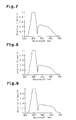
- the second light source 13 had the spectral characteristic shown in Fig. 7 , the correlated color temperature was 8000 K, and the S/P ratio was 3.11.
- the second light source 13 had the spectral characteristic shown in Fig. 8 , the correlated color temperature was 10000 K, and the S/P ratio was 3.40.
- the second light source 13 had the spectral characteristic shown in Fig. 9 , the correlated color temperature was 11900 K, and the SIP ratio was 3.63.
- the second light source 13 had the spectral characteristic shown in Fig. 10 , the correlated color temperature was 7920 K, and the S/P ratio was 2.07.
- the second light source 13 had the spectral characteristic shown in Fig. 11 , the correlated color temperature was 10000 K, and the S/P ratio was 2.28.
- the second light source 13 had the spectral characteristic shown in Fig. 12 , the correlated color temperature was 12000 K, and the SIP ratio was 3.46.
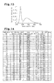
- the second light source 13 had the spectral characteristic shown in Fig. 12 , the correlated color temperature was 15200 K, and the S/P ratio was 2.52.
- the inventors combined a first light source 12 of one of the four conditions A1 to A4 with a second light source 13 of one of the seven conditions B1 to B7.
- the S/P ratio and color shift Duv for each of the combinations were calculated (refer to Fig. 14 ).
- the color shift Duv was in the range from 20 to -20 and the SIP ratio was 1.5 or greater.
- the color shift Duv was in the range from 10 to -10.
- the S/P ratio was 2.0 or greater.
- the activation controller 14 of the lighting device 10 which is supplied with power from the power supply PS, supplies current to and activates the first and second light sources 12 and 13.
- the activation controller 14 deactivates the second light sources 13 and activates only the first light sources 12.
- the first light sources 12 emit relatively warm light having a correlated color temperature of 4150 K or less.
- the light output of the second light sources 13 when there is no snow is greater than that of the first light sources by 2.4 to 2.6 times, preferably, by 2.5 times.
- the reflectivity of an asphalt road surface is approximately 20%
- the reflectivity of snow on a road is approximately 70%. That is, when the snow cover is present on a road, the reflectivity observed by a human is approximately 3.5 times greater than that when there is no snow on the road. Accordingly, when the snow cover is present, the second light sources 13 may be deactivated and only the first light sources 12 may be activated. In this case, the lighting device 10 would generate a light output that is approximately 1/3.5 of the light output generated when there is no snow.
- the light output of the second light sources 13 is set to be 2.4 to 2.6 times greater than the light output of the first light sources 12.
- the activation controller 14 deactivates the second light sources 13 when the snow cover is present. Instead, the activation controller 14 may dim the light emitted by the second light sources 13.
- Fig. 17 shows an example of the control performed when using the first and second light sources 12 and 13 of combination No. 24 in Fig. 14 .
- Fig. 18 shows an example of the control performed when using the first and second light sources 12 and 13 of combination No. 14 in Fig. 14 .
- the road surface condition when there is no snow is categorized as a "normal” condition, and the road surface condition when the snow cover is present is categorized into the four stages of "slight snow cover,” “intermediate,” “snow cover advancing,” and “snow covered.”
- the activation controller 14 activates the first light sources 12 so that the light output is 100% regardless of the road surface condition. As shown in Figs. 17 and 18 , under a "slight snow cover” condition, the activation controller 14 activates the second light sources 13 so that the light output is 75%. Under an “intermediate” condition, the activation controller 14 activates the second light sources 13 so that the light output is 50%. Under a “snow cover advancing” condition, the activation controller 14 activates the second light sources 13 so that the light output is 25%. When the first and second light sources 12 and 13 are both activated, the S/P ratio is preferably 2 or greater as shown in Figs. 17 and 18 . Under a "snow covered” condition, the light output of the second light sources 13 is 0%. That is, the second light sources 13 are deactivated.
- the snow detector 15 detects the present of the snow cover in an area conforming to the area illuminated by the light of the lighting device 10.
- the lighting device 10 may detect the present of the snow cover in an area outside the area illuminated by the light of the lighting device 10.
- a dimming switch 20 operable by a user may be arranged on the lighting device 10, and the dimming switch 20 may be used to perform dimming control that activates or dims the second lighting sources 13.
- the first light sources 12 have the spectral characteristics shown in Figs. 3 to 6
- the second light sources 13 have the light sources shown in Figs. 7 to 13 .
- the S/P ratio of the first light sources is less than the S/P ratio of the second light sources, the spectral characteristics of the first and second light sources 12 and 13 may be changed.
- the first light sources 12 are arranged in the central section of the flat base CB, and the second light sources 13 are arranged around the first light sources 12.
- the first and second light sources 12 and 13 may be arranged randomly as shown in Fig. 15 .
- the first and second light sources 12 and 13 are arranged on the flat base CB.
- the base CB may have a curved surface, and the first and second light sources 12 and 13 may be arranged along the curved surface.
- first light sources 12 and six second light sources 13 there are, for example, three first light sources 12 and six second light sources 13. However, the number of the first and second light sources 12 and 13 may be changed.
- the light output ratio of the first and second light sources 12 and 13 are set based on an asphalt road surface.
- the light output ratio of the first and second light sources 12 and 13 may be set based on a road surface of concrete or other materials.
- the reflectivity of a concrete road surface is approximately 31%, and the reflectivity of snow on a road is approximately 70%. That is, when the snow cover is present on a road, the reflectivity observed by a human is approximately 2.2 times greater than that when there is no snow on the road.
- the activation controller 14 controls the light output of the second light sources 13 to be 1.1 to 1.3 times greater than the light output of the first light sources 12. Accordingly, when the snow cover is present, the activation controller 14 deactivates the second light sources 13 and activates only the first light sources 12 so that the light output of the lighting device 10 is 1/2.2. Nevertheless, a pedestrian or the like would perceive the light as having a brightness that is about the same as that when there is no snow. Taking into consideration wear and paving errors of a road, the light output of the second light sources 13 is set to be 1.1 to 1.3 times greater than the light output of the first light sources 12.
- the inventors of the present invention combined a first light source 12 of one of conditions A1 to A4 with a second light source 13 of one of the seven conditions B1 to B7 and calculated the S/P ratio and color shift Duv for each of the combinations.
- the color shift Duv was in the range from 15 to -15 and the S/P ratio was 1.5 or greater.
- the color shift Duv was in the range from 10 to -10.
- the S/P ratio was 2.0 or greater.
- Fig. 20 shows an example of the control performed when using the first and second light sources 12 and 13 of combination No. X24 in Fig. 19 .
- Fig. 21 shows an example of the control performed when using the first and second light sources 12 and 13 of combination No. X17 in Fig. 19 .
- the road surface condition when there is no snow is categorized as a "normal” condition, and the road surface condition when the snow cover is present is categorized into the four stages of "slight snow cover,” “intermediate,” “snow cover advancing,” and “snow covered.”
- the activation controller 14 activates the first light sources 12 so that the light output is 100% regardless of the road surface condition. As shown in Figs. 20 and 21 , under a "slight snow cover” condition, the activation controller 14 activates the second light sources 13 so that the light output is 75%. Under an “intermediate” condition, the activation controller 14 activates the second light sources 13 so that the light output is 50%. Under a “snow cover advancing” condition, the activation controller 14 activates the second light sources 13 so that the light output is 25%. When the first and second light sources 12 and 13 are both activated, the S/P ratio is preferably 2 or greater as shown in Figs. 20 and 21 . Under a "snow covered” condition, the light output of the second light sources 13 is 0%. That is, the second light sources 13 are deactivated.
- the lighting device 10 may be configured so that when a user selects the road surface type (asphalt or concrete), the light output of the first and second light sources 12 and 13 are automatically set in accordance with the selection.
- the lighting device 10 may also be configured to automatically select the road surface type from the reflectivity of the road surface when there is no snow, and automatically set the light output of the first and second light sources 12 and 13.
- the transparent plate 11b includes a diffusion filter.
- the diffusion filter may be omitted.
- ridges and valley may be formed in the surface transparent plate 11b to diffuse light.
Landscapes
- Circuit Arrangement For Electric Light Sources In General (AREA)
Applications Claiming Priority (2)
| Application Number | Priority Date | Filing Date | Title |
|---|---|---|---|
| JP2012157685 | 2012-07-13 | ||
| JP2012202453A JP6032475B2 (ja) | 2012-07-13 | 2012-09-14 | 照明装置 |
Publications (2)
| Publication Number | Publication Date |
|---|---|
| EP2685790A2 true EP2685790A2 (fr) | 2014-01-15 |
| EP2685790A3 EP2685790A3 (fr) | 2017-04-05 |
Family
ID=48900751
Family Applications (1)
| Application Number | Title | Priority Date | Filing Date |
|---|---|---|---|
| EP13176131.4A Withdrawn EP2685790A3 (fr) | 2012-07-13 | 2013-07-11 | Dispositif d'éclairage |
Country Status (4)
| Country | Link |
|---|---|
| US (1) | US9084311B2 (fr) |
| EP (1) | EP2685790A3 (fr) |
| JP (1) | JP6032475B2 (fr) |
| CN (1) | CN103547025B (fr) |
Cited By (1)
| Publication number | Priority date | Publication date | Assignee | Title |
|---|---|---|---|---|
| WO2014123780A1 (fr) | 2013-02-08 | 2014-08-14 | Cree, Inc. | Dispositifs électroluminescents à semi-conducteurs comprenant un rapport scotopique/photopique réglable |
Families Citing this family (10)
| Publication number | Priority date | Publication date | Assignee | Title |
|---|---|---|---|---|
| JP2013058469A (ja) * | 2011-08-18 | 2013-03-28 | Panasonic Corp | 照明装置 |
| JP6032475B2 (ja) * | 2012-07-13 | 2016-11-30 | パナソニックIpマネジメント株式会社 | 照明装置 |
| US9993989B2 (en) | 2014-08-11 | 2018-06-12 | E I Du Pont De Nemours And Company | Composite sheet and cargo container comprising same |
| JP6562340B2 (ja) * | 2015-02-13 | 2019-08-21 | パナソニックIpマネジメント株式会社 | 照明装置およびそれを用いた照明器具 |
| PL3310725T3 (pl) * | 2015-06-18 | 2019-09-30 | Agc Glass Europe | Tafla szkła mająca wysoką transmisję promieniowania podczerwonego |
| JP6726857B2 (ja) * | 2016-06-03 | 2020-07-22 | パナソニックIpマネジメント株式会社 | 道路灯 |
| US11064591B2 (en) | 2016-09-22 | 2021-07-13 | Signify Holding B.V. | Flooding localization and signalling via intelligent lighting |
| CN111396787B (zh) * | 2020-04-17 | 2022-12-30 | 洛阳理工学院 | 一种基于中间视觉的高效率双色调光led路灯 |
| US11375588B1 (en) * | 2021-11-18 | 2022-06-28 | Roku, Inc. | Control a dimming level of an illumination load by a dimmer device |
| US20250119998A1 (en) * | 2023-10-06 | 2025-04-10 | Itron, Inc. | Directional streetlight control |
Citations (1)
| Publication number | Priority date | Publication date | Assignee | Title |
|---|---|---|---|---|
| JP2008091232A (ja) | 2006-10-03 | 2008-04-17 | Stanley Electric Co Ltd | 照明装置 |
Family Cites Families (21)
| Publication number | Priority date | Publication date | Assignee | Title |
|---|---|---|---|---|
| US4644452A (en) * | 1985-10-25 | 1987-02-17 | Kasboske George C | Vehicle headlamp with fog penetrating capability |
| US6144158A (en) | 1996-11-07 | 2000-11-07 | Sensci Corporation | Adaptive/anti-blinding headlights |
| US20120116632A1 (en) * | 1997-04-02 | 2012-05-10 | Bechtel Jon H | System for controlling vehicle equipment |
| US8120652B2 (en) * | 1997-04-02 | 2012-02-21 | Gentex Corporation | System for controlling vehicle equipment |
| TW493054B (en) * | 1999-06-25 | 2002-07-01 | Koninkl Philips Electronics Nv | Vehicle headlamp and a vehicle |
| JP2001126508A (ja) * | 1999-10-22 | 2001-05-11 | Koito Ind Ltd | 照明装置 |
| US8100552B2 (en) * | 2002-07-12 | 2012-01-24 | Yechezkal Evan Spero | Multiple light-source illuminating system |
| WO2004095007A1 (fr) * | 2003-04-24 | 2004-11-04 | Odyssey Energy Limited | Mesure de la reflectance d'une route et de l'eclairage routier |
| US7278737B2 (en) * | 2004-04-30 | 2007-10-09 | Advanced Medical Optics, Inc. | Ophthalmic devices having a highly selective violet light transmissive filter and related methods |
| GB0517959D0 (en) * | 2005-09-03 | 2005-10-12 | Mood Concepts Ltd | Improvements to lighting systems |
| JP2007276704A (ja) * | 2006-04-10 | 2007-10-25 | Denso Corp | 照明制御システム |
| JP4466608B2 (ja) * | 2006-05-18 | 2010-05-26 | 株式会社デンソー | 車両用前照灯装置 |
| US20080055065A1 (en) * | 2006-08-30 | 2008-03-06 | David Charles Feldmeier | Systems, devices, components and methods for controllably configuring the brightness of light emitted by an automotive LED illumination system |
| US7937667B2 (en) * | 2006-09-27 | 2011-05-03 | Donnelly Corporation | Multimedia mirror assembly for vehicle |
| CN101442855A (zh) | 2007-11-19 | 2009-05-27 | 梁普耀 | 机场照明自动控制方法 |
| US8308318B2 (en) * | 2009-05-01 | 2012-11-13 | Lighting Science Group Corporation | Sustainable outdoor lighting system |
| US20110252678A1 (en) * | 2010-04-12 | 2011-10-20 | Dale Jones | Method, apparatus and system for constant led night brightness based on daytime solar charging |
| CN202068616U (zh) * | 2011-04-06 | 2011-12-07 | 孝义市乐百利特科技有限责任公司 | 一种智能照明系统 |
| EP2721554A2 (fr) * | 2011-06-17 | 2014-04-23 | Robert Bosch GmbH | Procédé et appareil de commande permettant de détecter une condition météorologique dans un environnement d'un véhicule |
| JP6032475B2 (ja) * | 2012-07-13 | 2016-11-30 | パナソニックIpマネジメント株式会社 | 照明装置 |
| DE102013216225B4 (de) * | 2013-08-15 | 2024-11-14 | Robert Bosch Gmbh | Verfahren und Vorrichtung zum Steuern zumindest eines Scheinwerfers eines Fahrzeugs |
-
2012
- 2012-09-14 JP JP2012202453A patent/JP6032475B2/ja active Active
-
2013
- 2013-07-11 US US13/939,501 patent/US9084311B2/en active Active
- 2013-07-11 EP EP13176131.4A patent/EP2685790A3/fr not_active Withdrawn
- 2013-07-12 CN CN201310293794.0A patent/CN103547025B/zh active Active
Patent Citations (1)
| Publication number | Priority date | Publication date | Assignee | Title |
|---|---|---|---|---|
| JP2008091232A (ja) | 2006-10-03 | 2008-04-17 | Stanley Electric Co Ltd | 照明装置 |
Cited By (2)
| Publication number | Priority date | Publication date | Assignee | Title |
|---|---|---|---|---|
| WO2014123780A1 (fr) | 2013-02-08 | 2014-08-14 | Cree, Inc. | Dispositifs électroluminescents à semi-conducteurs comprenant un rapport scotopique/photopique réglable |
| EP2954565A4 (fr) * | 2013-02-08 | 2016-11-09 | Cree Inc | Dispositifs électroluminescents à semi-conducteurs comprenant un rapport scotopique/photopique réglable |
Also Published As
| Publication number | Publication date |
|---|---|
| CN103547025B (zh) | 2015-08-19 |
| EP2685790A3 (fr) | 2017-04-05 |
| JP2014032944A (ja) | 2014-02-20 |
| US9084311B2 (en) | 2015-07-14 |
| CN103547025A (zh) | 2014-01-29 |
| JP6032475B2 (ja) | 2016-11-30 |
| US20140015444A1 (en) | 2014-01-16 |
Similar Documents
| Publication | Publication Date | Title |
|---|---|---|
| US9084311B2 (en) | Lighting device | |
| CN102563417B (zh) | 照明装置 | |
| JP5923734B2 (ja) | 照明装置 | |
| JP5780904B2 (ja) | 照明装置 | |
| JP2010534907A (ja) | 照明装置 | |
| JP6157006B2 (ja) | 多領域照明制御器 | |
| WO2011105423A1 (fr) | Dispositif d'éclairage | |
| US7165876B2 (en) | Illuminating device utilizing light-emitting diode array | |
| US9247604B2 (en) | Lighting device | |
| KR100775908B1 (ko) | 혼합 광색 전기스탠드 | |
| JP4888351B2 (ja) | 照明装置およびそれを用いた照明器具 | |
| JP2012048860A (ja) | 照明装置 | |
| US9474116B2 (en) | Minimized color shift lighting arrangement during dimming | |
| JP3933175B2 (ja) | 照明装置 | |
| KR20120016690A (ko) | 색온도 제어가 가능한 조명시스템 및 그를 이용한 제어방법 | |
| JP2016219389A (ja) | 照明装置 | |
| JP5925367B2 (ja) | 照明装置 | |
| JP5165257B2 (ja) | Led照明器具装置 | |
| JP4047680B2 (ja) | 点灯ゲージつき照明用リモコン送信器 | |
| JP2013038062A (ja) | 照明装置及びその発光制御方法 | |
| JP2011165626A (ja) | 表示装置 | |
| TWI594663B (zh) | 光源驅動器及包含此光源驅動器之照明裝置 | |
| JP6593576B2 (ja) | 非常用照明装置 | |
| CN102606906B (zh) | 照明装置 | |
| JP2006085934A (ja) | 照明制御システム |
Legal Events
| Date | Code | Title | Description |
|---|---|---|---|
| PUAI | Public reference made under article 153(3) epc to a published international application that has entered the european phase |
Free format text: ORIGINAL CODE: 0009012 |
|
| 17P | Request for examination filed |
Effective date: 20130711 |
|
| AK | Designated contracting states |
Kind code of ref document: A2 Designated state(s): AL AT BE BG CH CY CZ DE DK EE ES FI FR GB GR HR HU IE IS IT LI LT LU LV MC MK MT NL NO PL PT RO RS SE SI SK SM TR |
|
| AX | Request for extension of the european patent |
Extension state: BA ME |
|
| RAP1 | Party data changed (applicant data changed or rights of an application transferred) |
Owner name: PANASONIC INTELLECTUAL PROPERTY MANAGEMENT CO., LT |
|
| PUAL | Search report despatched |
Free format text: ORIGINAL CODE: 0009013 |
|
| AK | Designated contracting states |
Kind code of ref document: A3 Designated state(s): AL AT BE BG CH CY CZ DE DK EE ES FI FR GB GR HR HU IE IS IT LI LT LU LV MC MK MT NL NO PL PT RO RS SE SI SK SM TR |
|
| AX | Request for extension of the european patent |
Extension state: BA ME |
|
| RIC1 | Information provided on ipc code assigned before grant |
Ipc: H05B 33/08 20060101AFI20170302BHEP Ipc: H05B 37/02 20060101ALI20170302BHEP |
|
| STAA | Information on the status of an ep patent application or granted ep patent |
Free format text: STATUS: EXAMINATION IS IN PROGRESS |
|
| 17Q | First examination report despatched |
Effective date: 20190604 |
|
| STAA | Information on the status of an ep patent application or granted ep patent |
Free format text: STATUS: THE APPLICATION HAS BEEN WITHDRAWN |
|
| 18W | Application withdrawn |
Effective date: 20190809 |