EP2685937B1 - Insert flottant pour prothèse du genou et prothèse du genou le comprenant - Google Patents
Insert flottant pour prothèse du genou et prothèse du genou le comprenant Download PDFInfo
- Publication number
- EP2685937B1 EP2685937B1 EP11710459.6A EP11710459A EP2685937B1 EP 2685937 B1 EP2685937 B1 EP 2685937B1 EP 11710459 A EP11710459 A EP 11710459A EP 2685937 B1 EP2685937 B1 EP 2685937B1
- Authority
- EP
- European Patent Office
- Prior art keywords
- insert
- femoral
- curvature
- radius
- posterior
- Prior art date
- Legal status (The legal status is an assumption and is not a legal conclusion. Google has not performed a legal analysis and makes no representation as to the accuracy of the status listed.)
- Active
Links
- 210000000629 knee joint Anatomy 0.000 title claims description 22
- 210000003127 knee Anatomy 0.000 claims description 13
- 241001227561 Valgus Species 0.000 claims description 4
- 241000469816 Varus Species 0.000 claims description 4
- QCWXUUIWCKQGHC-UHFFFAOYSA-N Zirconium Chemical compound [Zr] QCWXUUIWCKQGHC-UHFFFAOYSA-N 0.000 claims description 4
- 229910052726 zirconium Inorganic materials 0.000 claims description 4
- 239000004699 Ultra-high molecular weight polyethylene Substances 0.000 claims description 3
- 239000000919 ceramic Substances 0.000 claims description 3
- 229920000785 ultra high molecular weight polyethylene Polymers 0.000 claims description 3
- 238000002513 implantation Methods 0.000 description 4
- 239000000463 material Substances 0.000 description 3
- 210000004872 soft tissue Anatomy 0.000 description 3
- 210000002303 tibia Anatomy 0.000 description 3
- 210000000689 upper leg Anatomy 0.000 description 3
- 206010023204 Joint dislocation Diseases 0.000 description 2
- 210000000988 bone and bone Anatomy 0.000 description 2
- 239000007943 implant Substances 0.000 description 2
- 210000003041 ligament Anatomy 0.000 description 2
- 210000003205 muscle Anatomy 0.000 description 2
- 238000005299 abrasion Methods 0.000 description 1
- 230000002411 adverse Effects 0.000 description 1
- 238000010009 beating Methods 0.000 description 1
- 239000002639 bone cement Substances 0.000 description 1
- 239000002775 capsule Substances 0.000 description 1
- 238000006243 chemical reaction Methods 0.000 description 1
- 230000006735 deficit Effects 0.000 description 1
- 210000002414 leg Anatomy 0.000 description 1
- 238000000034 method Methods 0.000 description 1
- 229920003229 poly(methyl methacrylate) Polymers 0.000 description 1
- 239000004926 polymethyl methacrylate Substances 0.000 description 1
- 239000000602 vitallium Substances 0.000 description 1
Images


Classifications
-
- A—HUMAN NECESSITIES
- A61—MEDICAL OR VETERINARY SCIENCE; HYGIENE
- A61F—FILTERS IMPLANTABLE INTO BLOOD VESSELS; PROSTHESES; DEVICES PROVIDING PATENCY TO, OR PREVENTING COLLAPSING OF, TUBULAR STRUCTURES OF THE BODY, e.g. STENTS; ORTHOPAEDIC, NURSING OR CONTRACEPTIVE DEVICES; FOMENTATION; TREATMENT OR PROTECTION OF EYES OR EARS; BANDAGES, DRESSINGS OR ABSORBENT PADS; FIRST-AID KITS
- A61F2/00—Filters implantable into blood vessels; Prostheses, i.e. artificial substitutes or replacements for parts of the body; Appliances for connecting them with the body; Devices providing patency to, or preventing collapsing of, tubular structures of the body, e.g. stents
- A61F2/02—Prostheses implantable into the body
- A61F2/30—Joints
- A61F2/38—Joints for elbows or knees
- A61F2/3868—Joints for elbows or knees with sliding tibial bearing
-
- A—HUMAN NECESSITIES
- A61—MEDICAL OR VETERINARY SCIENCE; HYGIENE
- A61F—FILTERS IMPLANTABLE INTO BLOOD VESSELS; PROSTHESES; DEVICES PROVIDING PATENCY TO, OR PREVENTING COLLAPSING OF, TUBULAR STRUCTURES OF THE BODY, e.g. STENTS; ORTHOPAEDIC, NURSING OR CONTRACEPTIVE DEVICES; FOMENTATION; TREATMENT OR PROTECTION OF EYES OR EARS; BANDAGES, DRESSINGS OR ABSORBENT PADS; FIRST-AID KITS
- A61F2/00—Filters implantable into blood vessels; Prostheses, i.e. artificial substitutes or replacements for parts of the body; Appliances for connecting them with the body; Devices providing patency to, or preventing collapsing of, tubular structures of the body, e.g. stents
- A61F2/02—Prostheses implantable into the body
- A61F2/30—Joints
- A61F2/38—Joints for elbows or knees
- A61F2002/3895—Joints for elbows or knees unicompartimental
-
- A—HUMAN NECESSITIES
- A61—MEDICAL OR VETERINARY SCIENCE; HYGIENE
- A61F—FILTERS IMPLANTABLE INTO BLOOD VESSELS; PROSTHESES; DEVICES PROVIDING PATENCY TO, OR PREVENTING COLLAPSING OF, TUBULAR STRUCTURES OF THE BODY, e.g. STENTS; ORTHOPAEDIC, NURSING OR CONTRACEPTIVE DEVICES; FOMENTATION; TREATMENT OR PROTECTION OF EYES OR EARS; BANDAGES, DRESSINGS OR ABSORBENT PADS; FIRST-AID KITS
- A61F2250/00—Special features of prostheses classified in groups A61F2/00 - A61F2/26 or A61F2/82 or A61F9/00 or A61F11/00 or subgroups thereof
- A61F2250/0014—Special features of prostheses classified in groups A61F2/00 - A61F2/26 or A61F2/82 or A61F9/00 or A61F11/00 or subgroups thereof having different values of a given property or geometrical feature, e.g. mechanical property or material property, at different locations within the same prosthesis
- A61F2250/0037—Special features of prostheses classified in groups A61F2/00 - A61F2/26 or A61F2/82 or A61F9/00 or A61F11/00 or subgroups thereof having different values of a given property or geometrical feature, e.g. mechanical property or material property, at different locations within the same prosthesis differing in height or in length
-
- A—HUMAN NECESSITIES
- A61—MEDICAL OR VETERINARY SCIENCE; HYGIENE
- A61F—FILTERS IMPLANTABLE INTO BLOOD VESSELS; PROSTHESES; DEVICES PROVIDING PATENCY TO, OR PREVENTING COLLAPSING OF, TUBULAR STRUCTURES OF THE BODY, e.g. STENTS; ORTHOPAEDIC, NURSING OR CONTRACEPTIVE DEVICES; FOMENTATION; TREATMENT OR PROTECTION OF EYES OR EARS; BANDAGES, DRESSINGS OR ABSORBENT PADS; FIRST-AID KITS
- A61F2310/00—Prostheses classified in A61F2/28 or A61F2/30 - A61F2/44 being constructed from or coated with a particular material
- A61F2310/00005—The prosthesis being constructed from a particular material
- A61F2310/00179—Ceramics or ceramic-like structures
-
- A—HUMAN NECESSITIES
- A61—MEDICAL OR VETERINARY SCIENCE; HYGIENE
- A61F—FILTERS IMPLANTABLE INTO BLOOD VESSELS; PROSTHESES; DEVICES PROVIDING PATENCY TO, OR PREVENTING COLLAPSING OF, TUBULAR STRUCTURES OF THE BODY, e.g. STENTS; ORTHOPAEDIC, NURSING OR CONTRACEPTIVE DEVICES; FOMENTATION; TREATMENT OR PROTECTION OF EYES OR EARS; BANDAGES, DRESSINGS OR ABSORBENT PADS; FIRST-AID KITS
- A61F2310/00—Prostheses classified in A61F2/28 or A61F2/30 - A61F2/44 being constructed from or coated with a particular material
- A61F2310/00005—The prosthesis being constructed from a particular material
- A61F2310/00179—Ceramics or ceramic-like structures
- A61F2310/00185—Ceramics or ceramic-like structures based on metal oxides
- A61F2310/00239—Ceramics or ceramic-like structures based on metal oxides containing zirconia or zirconium oxide ZrO2
Definitions
- the present invention relates to a floating insert for a knee joint prosthesis and to a knee joint prosthesis including such an insert.
- the closest prior art is WO 2010/004342 A2 , which defines the preamble of claim 1.
- prosthetic devices are available for knee joint replacement. These include bicondylar prosthetic devices, where both condyles of the knee are replaced, and unicondylar prosthetic devices wherein only one of the knee condyles is replaced.
- tibial components are used to replace either or both of the medial and lateral condyles of the patient.
- a single, total femoral component or two partial femoral components may then be used to cooperate with the tibial component or components.
- unicondylar prostheses have to be precisely installed otherwise they are prone to failure. The Oxford unicondylar knee system was introduced to overcome this problem.
- a floating insert is located between a tibial component in the form of a tibial tray and the femoral component so that the insert can move with respect to both the tibial tray and the femoral component.
- the insert floats relative to the tibial component, it is free to rotate but excessive rotation of is undesirable.
- One aim of the present invention is to provide a floating insert for use in a unicondylar knee joint prosthesis that is adapted to limit rotation of the insert relative to a tibial tray of the prosthesis.
- a further aim is to provide a knee joint prosthesis including the aforementioned floating insert.
- a floating insert for a unicondylar knee joint prosthesis as defined in claim 1.
- an angle between the intercondylar side and a posterior side of the insert is equal to or less than 90°.
- corners between a superficial side of the insert and its posterior and anterior sides are rounded.
- a surface of the tibial side of the insert is smooth.
- an anterior-posterior profile of the insert is substantially wedge-shaped with an anterior height greater than a posterior height.
- the difference in height between a deepest point of the femoral side and a posterior edge of the femoral side is no greater than 3 mm and is preferably of the order of 2mm
- the difference in height between a deepest point of the femoral side and an anterior edge of the femoral side is between 2mm and 6 mm inclusive and is preferably of the order of 4 mm.
- the insert is comprised of one or a combination of an ultra high molecular weight polyethylene, a ceramic or oxidized zirconium.
- a unicondylar knee joint prosthesis comprising a femoral component, a tibial tray, and a floating insert, the floating insert being in accordance with the first aspect of die present invention.
- the tibial tray comprises a platform including a proximal bearing surface and a distal fixation surface, wherein the proximal bearing surface is smooth.
- the platform of the tibial tray defines a wall that projects in a proximal direction at a intercondylar edge of the proximal bearing surface.
- the wall extends proximally, in use, in a sagittal plane.
- said outer surface of the femoral component defines two regions for flexion rotation in a sagittal plane of which a first region has a first radius of curvature and a second region has a second radius of curvature, the first radius of curvature being larger than the second radius of curvature, and the surface of the femoral side of the insert has substantially the same radius of curvature in the sagittal plane as the first radius of curvature of the femoral component.
- said outer surface of the femoral component has a third radius of curvature for varus/valgus rotation in a coronal plane, and the surface of the femoral side of the insert has substantially the same radius of curvature in the coronal plane as the third radius of curvature of the femoral component.
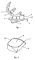
- a unicondylar knee joint prosthesis such as is shown in Fig. 1 comprises a tibial tray 1, a femoral component 2 and a floating insert 3.
- the insert has a femoral side 4 shaped to interface slidingly with an outer surface 5 of the femoral component 2 during flexion of the knee and a tibial side 6 shaped to interface slidingly with a proximal bearing surface 7 of the tibial tray 1.
- the femoral side 4 of the insert is therefore concave whereas the tibial side 6 of the insert is smooth.
- the femoral side 4 is generally planar like the proximal bearing surface 5 of the tibial tray 1 but it could also be convex, concave, curved in a medial-lateral plane and/or curved in an anterior-posterior plane.
- Both the tibial tray 1 and the femoral component 2 are preferably made of a material that provides a smooth sliding surface, is sufficiently rigid and durable, and will not cause adverse patient reactions, for example a cobalt chromium molybdenum alloy or oxidized zirconium.
- the floating insert 3 is preferably made of a material that can provide a good sliding interface with both the tibial tray 1 and the femoral component 2 and that also provides good friction and wear characteristics.
- An example of a suitable material for the insert 3 is ultra high molecular weight polyethylene, a ceramic, oxidized zirconium or a combination of these.
- the tibial tray 1 and the femoral component 2 are both designed to be cemented in position. Conventional bone cements, such as those based on polymethylmethacrylate can be used.
- FIG. 2 to 6 An embodiment of the floating insert for use in such a prosthesis is shown in Figs. 2 to 6 .
- the embodiment of knee joint prosthesis and therefore the floating insert shown in Figs. 1 and 11 to 13 of the drawings is shaped for implantation in the lateral side of a left knee or the medial side of a right knee of a patient.
- a knee joint prostheses suitable for implantation in the medial side of a left knee or the lateral side of a right knee of a patient would be a mirror image of these illustrated prosthesis and the insert 3 for forming part of these prostheses is as shown in Figs. 2 to 6 of the drawings.
- the floating insert 3 is pushed into position between the femoral component 2 and the tibial tray 1 after these implants have been fitted to a femur and adjacent tibia of a patient.
- the anterior-posterior profile of the insert 3 is therefore substantially wedge-shaped with the anterior height greater than the posterior height so that it can be pushed into position from an anterior side.
- the difference in height between the lowest and highest parts of the concave femoral side 4 defines the resistance against luxation of the prosthesis.
- the difference H1 in height between the deepest point of the femoral side 4 and a posterior edge 8 of the femoral side 4 should be no greater than around 3 mm and is preferably of the order of 2 mm otherwise too much force is required to push the insert 3 into position between the tibial tray 1 and the femoral component 2.
- Luxation towards the anterior is prevented by a difference in height H2 between the deepest point of the femoral side 4 of the insert 3 and an anterior edge 9 of the femoral side 4 is between 2mm and 6 mm inclusive and is preferably of the order of 4 mm.
- the tibial tray 1 of the knee joint prosthesis is shown in Figs. 7 to 9 of the drawings and comprises a platform 10 defining the proximal bearing surface 7 and a distal fixation surface 11. Projecting from die distal fixation surface 11 is a keel 12 that extends in an anterior-posterior direction with respect to the position of the tray 1 when in use. The keel 12 facilitates positioning and fixation of the tray 1 during implantation to a resected end of a tibia.
- the proximal bearing surface 7 of the tray 1 is smooth and generally planar so that the tibial side 6 of the insert 3 is also smooth and generally planar.
- a projecting wall 13 that is linear and that in use extends in a sagittal plane from the proximal bearing surface 7 and projects in a proximal direction.
- the wall 13 is therefore located on the intercondylar side of the tray 1 and is provided to prevent dislocation of the insert 3 during use and to prevent abrasion of the insert 3 by adjacent bone.
- the superficial, anterior and posterior edges of die platform 10 form a continuous, asymmetric curve which approximates to the exterior profile of die underlying bone so that there is minimal impairment of the function of the cruciate ligaments and leg muscles when the implant is in use.
- the insert 3 is asymmetric about its sagittal plane although the surface defined by the femoral side 4 is symmetric about this plane and is approximately rectangular but with rounded corners. Beneath this femoral surface, the insert 3 is shaped to prevent excess rotation relative to the tibial tray 1 from taking place during use and to protect surrounding soft tissues from damage. It has a intercondylar side 14 that extends linearly and that is adapted for location adjacent the wall 13 of the tibial tray 1. This side 14 is longer in length than am opposite superficial side 15 of the insert 3, which has a rounded profile. Contact between the longer intercondylar side 14 of the insert 3 and the wall 13 limits extensive rotation of the insert 3 relative to the tibial tray 1 as the knee joint is moved.
- the corner 16 at the posterior end of the intercondylar side 14 may be extended and project rearwardly as shown in Fig. 3 for the express purpose of preventing extensive rotation relating to the tibial tray 1.
- the angle A1 between die intercondylar side 14 and the posterior side of insert 3 is therefore equal to or less than 90° and is typically around 80°.
- the corner A2 between the intercondylar side 14 and the anterior side of the insert is around 90° although the actual apexes of both corners are rounded.
- the corners between the superficial side 15 of the insert and its posterior and anterior sides are rounded in order to protect the surrounding soft tissue from damage during deep flexion and during hyperextension of the knee.
- the surface 5 of the femoral component 2 defines two regions 17 and 18 for flexion rotation in a sagittal plane of which the first region 16 has a first radius of curvature R1 and die second region 18 has a second radius of curvature R2.
- the surface 18 with the second radius of curvature R2 defines the posterior part of the component 2 while the surface 17 with the first radius of curvature R1 defines the anterior part of the component 2 and imitates the distal shape of the femoral condyles.
- the first radius of curvature R1 is larger than the second radius of curvature R2 and typically the ratio of these two radii is around 1.5:1.
- the surface 5 of the femoral component 2 also has a third radius of curvature R3 in a coronal plane for varus/valgus rotation, as shown in Fig. 13 .
- the radius of curvature R3 is substantially the same as the radius of curvature R2. This means that the surface 18 of the posterior part of the component 2 is spheroidal whereas the surface 17 of the distal or anterior part of the component 2 is toroidal.
- the concave nature of the femoral side 4 of the insert 3 is such that its surface has substantially the same radius of curvature in the sagittal plane as the first radius of curvature R1 of the distal part of the femoral component 2. This means that there is maximum congruency between the insert 3 and the femoral component 2 in extension.
- this surface in the coronal plane has substantially the same radius of curvature as the third radius of curvature R3 of the femoral component 2. This allows varus/valgus rotation of the knee in a coronal plan of up to around 8°.
- the generally planar nature of the proximal bearing surface 7 of the tibial tray 1 means that it is not able to guide motion between the femur and the tibia of the patient during movement of the knee joint. This has to be controlled by the patient's own muscles, the capsule and the ligaments around the knee joint. It is therefore important that the prosthesis is implanted with precision in a manner which causes minimum damage to the soft tissues around the knee.
- the prosthesis is designed to allow a range of motion between around 8° hyper-extension to around 125° flexion. Flexion much beyond 125° depends on the way the bony overhang on the posterior femoral condyle is treated. Preferably, the overhang is removed to prevent impingement between the femur and the insert 3 at greater than 125° of flexion.
- both regions 17 and 18 of the surface 5 are in contact with the surface 4 of the insert 3 and the contact area between the component 2 and the insert 3 is reduced. Thereafter, beyond approximately 80° only the region 18 of the surface 5 is in contact with the surface 4 of the insert 3 and the contact area between the component 2 and the insert 3 is at its smallest. However, the load between them is at its smallest too. The largest loading between the two components 2 and 3 occurs between 0° and around 30° of flexion when they are both fully congruent.
Landscapes
- Health & Medical Sciences (AREA)
- Orthopedic Medicine & Surgery (AREA)
- Physical Education & Sports Medicine (AREA)
- Cardiology (AREA)
- Oral & Maxillofacial Surgery (AREA)
- Transplantation (AREA)
- Engineering & Computer Science (AREA)
- Biomedical Technology (AREA)
- Heart & Thoracic Surgery (AREA)
- Vascular Medicine (AREA)
- Life Sciences & Earth Sciences (AREA)
- Animal Behavior & Ethology (AREA)
- General Health & Medical Sciences (AREA)
- Public Health (AREA)
- Veterinary Medicine (AREA)
- Prostheses (AREA)
Claims (14)
- Un insert flottant (3) pour une prothèse d'articulation de genou unicondylienne comprenant un composant fémoral (2) et un plateau tibial (1), l'insert (3) ayant un côté fémoral (4) conformé pour être raccordé de façon à glisser avec une surface externe (5) du composant fémoral (2) durant la flexion du genou et un côté tibial (6) conformé pour être raccordé de façon à glisser avec une surface d'appui proximale (7) du plateau tibial (1) durant la flexion du genou, l'insert ayant un côté intercondylien (14) et un côté superficiel opposé (15), l'insert n'étant pas symétrique autour d'un plan sagittal, le côté intercondylien (14) étant de plus grande longueur que le côté superficiel (15) et étant caractérisé en ce qu'un coin (16) au niveau d'une extrémité postérieure du côté intercondylien (14) est étendu pour faire saillie vers l'arrière.
- Un insert (3) tel que revendiqué dans la revendication 1, dans lequel un angle (A1) entre le côté intercondylien (14) et un côté postérieur de l'insert (3) est égal ou inférieur à 90°.
- Un insert (3) tel que revendiqué dans la revendication 1 ou la revendication 2, dans lequel des coins entre le côté superficiel (15) de l'insert et ses côtés postérieur et antérieur sont arrondis.
- Un insert (3) tel que revendiqué dans n'importe lesquelles des revendications 1 à 3, dans lequel une surface du côté tibial (6) est lisse.
- Un insert (3) tel que revendiqué dans n'importe lesquelles des revendications 1 à 4, dans lequel un profil antérieur-postérieur est substantiellement conformé comme une cale avec une hauteur antérieure supérieure à une hauteur postérieure.
- Un insert (3) tel que revendiqué dans n'importe lesquelles des revendications 1 à 5, dans lequel, dans un plan sagittal, la différence de hauteur (H1) entre un point le plus profond du côté fémoral (4) et un bord postérieur (8) du côté fémoral (4) n'est pas supérieure à 3 mm et est de préférence de l'ordre de 2 mm.
- Un insert (3) tel que revendiqué dans n'importe lesquelles des revendications 1 à 6, dans lequel, dans un plan sagittal, la différence de hauteur (H2) entre un point le plus profond du côté fémoral (4) et un bord antérieur (9) du côté fémoral (4) est comprise entre 2 mm et 6 mm inclus et est de préférence de l'ordre de 4 mm.
- Un insert (3) tel que revendiqué dans n'importe lesquelles des revendications 1 à 7, lequel étant constitué d'un élément ou d'une combinaison de matériaux parmi un polyéthylène à poids moléculaire ultra élevé, une céramique ou un zirconium oxydé.
- Une prothèse d'articulation de genou unicondylienne comprenant un composant fémoral (2), un plateau tibial (1), et un insert flottant (3), l'insert flottant (3) étant tel que revendiqué dans n'importe lesquelles des revendications 1 à 8.
- Une prothèse telle que revendiquée dans la revendication 9, dans laquelle le plateau tibial (1) comprend une plateforme (10) incluant une surface d'appui proximale (7) et une surface de fixation distale (11), la surface d'appui proximale (7) étant lisse.
- Une prothèse telle que revendiquée dans la revendication 10, dans laquelle la plateforme (10) du plateau tibial (1) définit une paroi (13) qui fait saillie dans une direction proximale au niveau d'un bord intercondylien de la surface d'appui proximale (7).
- Une prothèse telle que revendiquée dans la revendication 11, dans laquelle la paroi (13) s'étend proximalement, lors de l'utilisation, dans un plan sagittal.
- Une prothèse telle que revendiquée dans n'importe lesquelles des revendications 9 à 12 dans laquelle une surface externe (5) du composant fémoral (2) définit des première et deuxième régions (17, 18) pour la rotation en flexion dans un plan sagittal, la première région (17) ayant un premier rayon de courbure (R1) et la deuxième région (18) ayant un deuxième rayon de courbure (R2), le premier rayon de courbure (R1) étant plus grand que le deuxième rayon de courbure (R2), et la surface du côté fémoral (4) de l'insert (3) ayant substantiellement le même rayon de courbure dans le plan sagittal que le premier rayon de courbure (R1) du composant fémoral (2).
- Une prothèse telle que revendiquée dans n'importe lesquelles des revendications 9 à 13, dans laquelle ladite surface externe (5) du composant fémoral (2) a un troisième rayon de courbure (R3) pour la rotation varus/valgus dans un plan frontal, et la surface du côté fémoral (4) de l'insert (3) a substantiellement le même rayon de courbure dans le plan frontal que le troisième rayon de courbure (R3) du composant fémoral (2).
Applications Claiming Priority (1)
| Application Number | Priority Date | Filing Date | Title |
|---|---|---|---|
| PCT/EP2011/054140 WO2012126497A1 (fr) | 2011-03-18 | 2011-03-18 | Insert flottant pour prothèse du genou et prothèse du genou le comprenant |
Publications (2)
| Publication Number | Publication Date |
|---|---|
| EP2685937A1 EP2685937A1 (fr) | 2014-01-22 |
| EP2685937B1 true EP2685937B1 (fr) | 2015-11-25 |
Family
ID=44168388
Family Applications (1)
| Application Number | Title | Priority Date | Filing Date |
|---|---|---|---|
| EP11710459.6A Active EP2685937B1 (fr) | 2011-03-18 | 2011-03-18 | Insert flottant pour prothèse du genou et prothèse du genou le comprenant |
Country Status (2)
| Country | Link |
|---|---|
| EP (1) | EP2685937B1 (fr) |
| WO (1) | WO2012126497A1 (fr) |
Families Citing this family (2)
| Publication number | Priority date | Publication date | Assignee | Title |
|---|---|---|---|---|
| CN211460685U (zh) * | 2019-04-22 | 2020-09-11 | 天津正天医疗器械有限公司 | 股骨假体及膝关节假体 |
| CN111467090B (zh) * | 2020-05-20 | 2025-09-16 | 苏州微创关节医疗科技有限公司 | 单髁股骨假体系统及单髁股骨假体 |
Family Cites Families (5)
| Publication number | Priority date | Publication date | Assignee | Title |
|---|---|---|---|---|
| EP1327424B1 (fr) * | 2002-01-11 | 2012-09-12 | Barry M. Fell | Endoprothèse du genou à surface tibiale déplacée médialement |
| DE10220591B4 (de) * | 2002-05-08 | 2004-03-18 | Mathys Medizinaltechnik Ag | Gelenkprothese mit Zwischenelement mit unterschiedlichen Krümmungsradien |
| US8147557B2 (en) * | 2007-03-30 | 2012-04-03 | Depuy Products, Inc. | Mobile bearing insert having offset dwell point |
| US8142510B2 (en) * | 2007-03-30 | 2012-03-27 | Depuy Products, Inc. | Mobile bearing assembly having a non-planar interface |
| GB0812631D0 (en) * | 2008-07-10 | 2008-08-20 | Imp Innovations Ltd | Modular knee implants |
-
2011
- 2011-03-18 EP EP11710459.6A patent/EP2685937B1/fr active Active
- 2011-03-18 WO PCT/EP2011/054140 patent/WO2012126497A1/fr not_active Ceased
Also Published As
| Publication number | Publication date |
|---|---|
| WO2012126497A1 (fr) | 2012-09-27 |
| EP2685937A1 (fr) | 2014-01-22 |
Similar Documents
| Publication | Publication Date | Title |
|---|---|---|
| US11730602B2 (en) | Orthopaedic knee prosthesis having controlled condylar curvature | |
| US11369478B2 (en) | Orthopaedic knee prosthesis having controlled condylar curvature | |
| US20220280305A1 (en) | Orthopaedic femoral component having controlled condylar curvature | |
| EP1684672B1 (fr) | Implant articulaire a flexion elevee | |
| EP2275053B1 (fr) | Prothèse de genou orthopédique | |
| EP2512380B1 (fr) | Implant destiné à restaurer une plage de flexion normale et des mouvements normaux du genou | |
| US20180064543A1 (en) | Knee prosthesis assembly having proportional trochlear groove geometry | |
| AU2012275457A1 (en) | Posterior stabilized orthopaedic knee prosthesis having controlled condylar curvature | |
| WO2012058540A1 (fr) | Système de genou | |
| EP2685936B1 (fr) | Plateau tibial pour prothèse du genou et prothèse du genou le comprenant | |
| EP2685937A1 (fr) | Insert flottant pour prothèse du genou et prothèse du genou le comprenant | |
| AU2013349254A1 (en) | Knee replacement prosthetic |
Legal Events
| Date | Code | Title | Description |
|---|---|---|---|
| PUAI | Public reference made under article 153(3) epc to a published international application that has entered the european phase |
Free format text: ORIGINAL CODE: 0009012 |
|
| 17P | Request for examination filed |
Effective date: 20131018 |
|
| AK | Designated contracting states |
Kind code of ref document: A1 Designated state(s): AL AT BE BG CH CY CZ DE DK EE ES FI FR GB GR HR HU IE IS IT LI LT LU LV MC MK MT NL NO PL PT RO RS SE SI SK SM TR |
|
| DAX | Request for extension of the european patent (deleted) | ||
| GRAP | Despatch of communication of intention to grant a patent |
Free format text: ORIGINAL CODE: EPIDOSNIGR1 |
|
| INTG | Intention to grant announced |
Effective date: 20140825 |
|
| GRAP | Despatch of communication of intention to grant a patent |
Free format text: ORIGINAL CODE: EPIDOSNIGR1 |
|
| INTG | Intention to grant announced |
Effective date: 20150504 |
|
| GRAS | Grant fee paid |
Free format text: ORIGINAL CODE: EPIDOSNIGR3 |
|
| GRAA | (expected) grant |
Free format text: ORIGINAL CODE: 0009210 |
|
| AK | Designated contracting states |
Kind code of ref document: B1 Designated state(s): AL AT BE BG CH CY CZ DE DK EE ES FI FR GB GR HR HU IE IS IT LI LT LU LV MC MK MT NL NO PL PT RO RS SE SI SK SM TR |
|
| REG | Reference to a national code |
Ref country code: GB Ref legal event code: FG4D |
|
| REG | Reference to a national code |
Ref country code: CH Ref legal event code: EP |
|
| REG | Reference to a national code |
Ref country code: AT Ref legal event code: REF Ref document number: 762216 Country of ref document: AT Kind code of ref document: T Effective date: 20151215 |
|
| REG | Reference to a national code |
Ref country code: IE Ref legal event code: FG4D |
|
| REG | Reference to a national code |
Ref country code: DE Ref legal event code: R096 Ref document number: 602011021601 Country of ref document: DE |
|
| REG | Reference to a national code |
Ref country code: FR Ref legal event code: PLFP Year of fee payment: 6 |
|
| REG | Reference to a national code |
Ref country code: LT Ref legal event code: MG4D |
|
| REG | Reference to a national code |
Ref country code: NL Ref legal event code: FP |
|
| REG | Reference to a national code |
Ref country code: AT Ref legal event code: MK05 Ref document number: 762216 Country of ref document: AT Kind code of ref document: T Effective date: 20151125 |
|
| PG25 | Lapsed in a contracting state [announced via postgrant information from national office to epo] |
Ref country code: HR Free format text: LAPSE BECAUSE OF FAILURE TO SUBMIT A TRANSLATION OF THE DESCRIPTION OR TO PAY THE FEE WITHIN THE PRESCRIBED TIME-LIMIT Effective date: 20151125 Ref country code: ES Free format text: LAPSE BECAUSE OF FAILURE TO SUBMIT A TRANSLATION OF THE DESCRIPTION OR TO PAY THE FEE WITHIN THE PRESCRIBED TIME-LIMIT Effective date: 20151125 Ref country code: LT Free format text: LAPSE BECAUSE OF FAILURE TO SUBMIT A TRANSLATION OF THE DESCRIPTION OR TO PAY THE FEE WITHIN THE PRESCRIBED TIME-LIMIT Effective date: 20151125 Ref country code: NO Free format text: LAPSE BECAUSE OF FAILURE TO SUBMIT A TRANSLATION OF THE DESCRIPTION OR TO PAY THE FEE WITHIN THE PRESCRIBED TIME-LIMIT Effective date: 20160225 Ref country code: IS Free format text: LAPSE BECAUSE OF FAILURE TO SUBMIT A TRANSLATION OF THE DESCRIPTION OR TO PAY THE FEE WITHIN THE PRESCRIBED TIME-LIMIT Effective date: 20160325 |
|
| PG25 | Lapsed in a contracting state [announced via postgrant information from national office to epo] |
Ref country code: FI Free format text: LAPSE BECAUSE OF FAILURE TO SUBMIT A TRANSLATION OF THE DESCRIPTION OR TO PAY THE FEE WITHIN THE PRESCRIBED TIME-LIMIT Effective date: 20151125 Ref country code: RS Free format text: LAPSE BECAUSE OF FAILURE TO SUBMIT A TRANSLATION OF THE DESCRIPTION OR TO PAY THE FEE WITHIN THE PRESCRIBED TIME-LIMIT Effective date: 20151125 Ref country code: PT Free format text: LAPSE BECAUSE OF FAILURE TO SUBMIT A TRANSLATION OF THE DESCRIPTION OR TO PAY THE FEE WITHIN THE PRESCRIBED TIME-LIMIT Effective date: 20160325 Ref country code: PL Free format text: LAPSE BECAUSE OF FAILURE TO SUBMIT A TRANSLATION OF THE DESCRIPTION OR TO PAY THE FEE WITHIN THE PRESCRIBED TIME-LIMIT Effective date: 20151125 Ref country code: SE Free format text: LAPSE BECAUSE OF FAILURE TO SUBMIT A TRANSLATION OF THE DESCRIPTION OR TO PAY THE FEE WITHIN THE PRESCRIBED TIME-LIMIT Effective date: 20151125 Ref country code: AT Free format text: LAPSE BECAUSE OF FAILURE TO SUBMIT A TRANSLATION OF THE DESCRIPTION OR TO PAY THE FEE WITHIN THE PRESCRIBED TIME-LIMIT Effective date: 20151125 Ref country code: LV Free format text: LAPSE BECAUSE OF FAILURE TO SUBMIT A TRANSLATION OF THE DESCRIPTION OR TO PAY THE FEE WITHIN THE PRESCRIBED TIME-LIMIT Effective date: 20151125 Ref country code: GR Free format text: LAPSE BECAUSE OF FAILURE TO SUBMIT A TRANSLATION OF THE DESCRIPTION OR TO PAY THE FEE WITHIN THE PRESCRIBED TIME-LIMIT Effective date: 20160226 |
|
| PG25 | Lapsed in a contracting state [announced via postgrant information from national office to epo] |
Ref country code: CZ Free format text: LAPSE BECAUSE OF FAILURE TO SUBMIT A TRANSLATION OF THE DESCRIPTION OR TO PAY THE FEE WITHIN THE PRESCRIBED TIME-LIMIT Effective date: 20151125 Ref country code: IT Free format text: LAPSE BECAUSE OF FAILURE TO SUBMIT A TRANSLATION OF THE DESCRIPTION OR TO PAY THE FEE WITHIN THE PRESCRIBED TIME-LIMIT Effective date: 20151125 |
|
| REG | Reference to a national code |
Ref country code: DE Ref legal event code: R097 Ref document number: 602011021601 Country of ref document: DE |
|
| PG25 | Lapsed in a contracting state [announced via postgrant information from national office to epo] |
Ref country code: EE Free format text: LAPSE BECAUSE OF FAILURE TO SUBMIT A TRANSLATION OF THE DESCRIPTION OR TO PAY THE FEE WITHIN THE PRESCRIBED TIME-LIMIT Effective date: 20151125 Ref country code: SK Free format text: LAPSE BECAUSE OF FAILURE TO SUBMIT A TRANSLATION OF THE DESCRIPTION OR TO PAY THE FEE WITHIN THE PRESCRIBED TIME-LIMIT Effective date: 20151125 Ref country code: RO Free format text: LAPSE BECAUSE OF FAILURE TO SUBMIT A TRANSLATION OF THE DESCRIPTION OR TO PAY THE FEE WITHIN THE PRESCRIBED TIME-LIMIT Effective date: 20151125 Ref country code: DK Free format text: LAPSE BECAUSE OF FAILURE TO SUBMIT A TRANSLATION OF THE DESCRIPTION OR TO PAY THE FEE WITHIN THE PRESCRIBED TIME-LIMIT Effective date: 20151125 Ref country code: SM Free format text: LAPSE BECAUSE OF FAILURE TO SUBMIT A TRANSLATION OF THE DESCRIPTION OR TO PAY THE FEE WITHIN THE PRESCRIBED TIME-LIMIT Effective date: 20151125 Ref country code: BE Free format text: LAPSE BECAUSE OF NON-PAYMENT OF DUE FEES Effective date: 20160331 |
|
| PLBE | No opposition filed within time limit |
Free format text: ORIGINAL CODE: 0009261 |
|
| STAA | Information on the status of an ep patent application or granted ep patent |
Free format text: STATUS: NO OPPOSITION FILED WITHIN TIME LIMIT |
|
| PG25 | Lapsed in a contracting state [announced via postgrant information from national office to epo] |
Ref country code: LU Free format text: LAPSE BECAUSE OF FAILURE TO SUBMIT A TRANSLATION OF THE DESCRIPTION OR TO PAY THE FEE WITHIN THE PRESCRIBED TIME-LIMIT Effective date: 20160318 Ref country code: MC Free format text: LAPSE BECAUSE OF FAILURE TO SUBMIT A TRANSLATION OF THE DESCRIPTION OR TO PAY THE FEE WITHIN THE PRESCRIBED TIME-LIMIT Effective date: 20151125 |
|
| 26N | No opposition filed |
Effective date: 20160826 |
|
| PG25 | Lapsed in a contracting state [announced via postgrant information from national office to epo] |
Ref country code: SI Free format text: LAPSE BECAUSE OF FAILURE TO SUBMIT A TRANSLATION OF THE DESCRIPTION OR TO PAY THE FEE WITHIN THE PRESCRIBED TIME-LIMIT Effective date: 20151125 |
|
| REG | Reference to a national code |
Ref country code: IE Ref legal event code: MM4A |
|
| PG25 | Lapsed in a contracting state [announced via postgrant information from national office to epo] |
Ref country code: BE Free format text: LAPSE BECAUSE OF FAILURE TO SUBMIT A TRANSLATION OF THE DESCRIPTION OR TO PAY THE FEE WITHIN THE PRESCRIBED TIME-LIMIT Effective date: 20151125 |
|
| PG25 | Lapsed in a contracting state [announced via postgrant information from national office to epo] |
Ref country code: IE Free format text: LAPSE BECAUSE OF NON-PAYMENT OF DUE FEES Effective date: 20160318 |
|
| REG | Reference to a national code |
Ref country code: FR Ref legal event code: PLFP Year of fee payment: 7 |
|
| PG25 | Lapsed in a contracting state [announced via postgrant information from national office to epo] |
Ref country code: MT Free format text: LAPSE BECAUSE OF FAILURE TO SUBMIT A TRANSLATION OF THE DESCRIPTION OR TO PAY THE FEE WITHIN THE PRESCRIBED TIME-LIMIT Effective date: 20151125 |
|
| REG | Reference to a national code |
Ref country code: FR Ref legal event code: PLFP Year of fee payment: 8 |
|
| PG25 | Lapsed in a contracting state [announced via postgrant information from national office to epo] |
Ref country code: CY Free format text: LAPSE BECAUSE OF FAILURE TO SUBMIT A TRANSLATION OF THE DESCRIPTION OR TO PAY THE FEE WITHIN THE PRESCRIBED TIME-LIMIT Effective date: 20151125 Ref country code: HU Free format text: LAPSE BECAUSE OF FAILURE TO SUBMIT A TRANSLATION OF THE DESCRIPTION OR TO PAY THE FEE WITHIN THE PRESCRIBED TIME-LIMIT; INVALID AB INITIO Effective date: 20110318 |
|
| PG25 | Lapsed in a contracting state [announced via postgrant information from national office to epo] |
Ref country code: MK Free format text: LAPSE BECAUSE OF FAILURE TO SUBMIT A TRANSLATION OF THE DESCRIPTION OR TO PAY THE FEE WITHIN THE PRESCRIBED TIME-LIMIT Effective date: 20151125 Ref country code: TR Free format text: LAPSE BECAUSE OF FAILURE TO SUBMIT A TRANSLATION OF THE DESCRIPTION OR TO PAY THE FEE WITHIN THE PRESCRIBED TIME-LIMIT Effective date: 20151125 Ref country code: MT Free format text: LAPSE BECAUSE OF FAILURE TO SUBMIT A TRANSLATION OF THE DESCRIPTION OR TO PAY THE FEE WITHIN THE PRESCRIBED TIME-LIMIT Effective date: 20160331 |
|
| PG25 | Lapsed in a contracting state [announced via postgrant information from national office to epo] |
Ref country code: BG Free format text: LAPSE BECAUSE OF FAILURE TO SUBMIT A TRANSLATION OF THE DESCRIPTION OR TO PAY THE FEE WITHIN THE PRESCRIBED TIME-LIMIT Effective date: 20151125 |
|
| PG25 | Lapsed in a contracting state [announced via postgrant information from national office to epo] |
Ref country code: AL Free format text: LAPSE BECAUSE OF FAILURE TO SUBMIT A TRANSLATION OF THE DESCRIPTION OR TO PAY THE FEE WITHIN THE PRESCRIBED TIME-LIMIT Effective date: 20151125 |
|
| REG | Reference to a national code |
Ref country code: DE Ref legal event code: R082 Ref document number: 602011021601 Country of ref document: DE Representative=s name: MURGITROYD & COMPANY, DE Ref country code: DE Ref legal event code: R081 Ref document number: 602011021601 Country of ref document: DE Owner name: SMITH & NEPHEW ORTHOPAEDICS AG, CH Free format text: FORMER OWNER: SMITH & NEPHEW ORTHOPAEDICS AG, ROTKREUZ, CH |
|
| REG | Reference to a national code |
Ref country code: CH Ref legal event code: NV Representative=s name: MURGITROYD AND COMPANY, CH Ref country code: CH Ref legal event code: PCOW Free format text: NEW ADDRESS: THEILERSTRASSE 1A, 6300 ZUG (CH) |
|
| PGFP | Annual fee paid to national office [announced via postgrant information from national office to epo] |
Ref country code: NL Payment date: 20220215 Year of fee payment: 12 |
|
| PGFP | Annual fee paid to national office [announced via postgrant information from national office to epo] |
Ref country code: FR Payment date: 20230110 Year of fee payment: 13 |
|
| PGFP | Annual fee paid to national office [announced via postgrant information from national office to epo] |
Ref country code: GB Payment date: 20230126 Year of fee payment: 13 Ref country code: DE Payment date: 20230125 Year of fee payment: 13 |
|
| P01 | Opt-out of the competence of the unified patent court (upc) registered |
Effective date: 20230522 |
|
| PGFP | Annual fee paid to national office [announced via postgrant information from national office to epo] |
Ref country code: CH Payment date: 20230401 Year of fee payment: 13 |
|
| REG | Reference to a national code |
Ref country code: NL Ref legal event code: MM Effective date: 20230401 |
|
| PG25 | Lapsed in a contracting state [announced via postgrant information from national office to epo] |
Ref country code: NL Free format text: LAPSE BECAUSE OF NON-PAYMENT OF DUE FEES Effective date: 20230401 |
|
| REG | Reference to a national code |
Ref country code: DE Ref legal event code: R119 Ref document number: 602011021601 Country of ref document: DE |
|
| REG | Reference to a national code |
Ref country code: CH Ref legal event code: PL |
|
| GBPC | Gb: european patent ceased through non-payment of renewal fee |
Effective date: 20240318 |
|
| PG25 | Lapsed in a contracting state [announced via postgrant information from national office to epo] |
Ref country code: DE Free format text: LAPSE BECAUSE OF NON-PAYMENT OF DUE FEES Effective date: 20241001 |
|
| PG25 | Lapsed in a contracting state [announced via postgrant information from national office to epo] |
Ref country code: GB Free format text: LAPSE BECAUSE OF NON-PAYMENT OF DUE FEES Effective date: 20240318 |
|
| PG25 | Lapsed in a contracting state [announced via postgrant information from national office to epo] |
Ref country code: FR Free format text: LAPSE BECAUSE OF NON-PAYMENT OF DUE FEES Effective date: 20240331 |
|
| PG25 | Lapsed in a contracting state [announced via postgrant information from national office to epo] |
Ref country code: GB Free format text: LAPSE BECAUSE OF NON-PAYMENT OF DUE FEES Effective date: 20240318 Ref country code: FR Free format text: LAPSE BECAUSE OF NON-PAYMENT OF DUE FEES Effective date: 20240331 Ref country code: DE Free format text: LAPSE BECAUSE OF NON-PAYMENT OF DUE FEES Effective date: 20241001 Ref country code: CH Free format text: LAPSE BECAUSE OF NON-PAYMENT OF DUE FEES Effective date: 20240331 |