EP2686053B1 - Befeuchter mit flüssigkeitseindringungsschutz - Google Patents
Befeuchter mit flüssigkeitseindringungsschutz Download PDFInfo
- Publication number
- EP2686053B1 EP2686053B1 EP12709384.7A EP12709384A EP2686053B1 EP 2686053 B1 EP2686053 B1 EP 2686053B1 EP 12709384 A EP12709384 A EP 12709384A EP 2686053 B1 EP2686053 B1 EP 2686053B1
- Authority
- EP
- European Patent Office
- Prior art keywords
- liquid
- chamber
- feed path
- flow
- humidification
- Prior art date
- Legal status (The legal status is an assumption and is not a legal conclusion. Google has not performed a legal analysis and makes no representation as to the accuracy of the status listed.)
- Not-in-force
Links
- 239000007788 liquid Substances 0.000 title claims description 137
- 238000003860 storage Methods 0.000 claims description 73
- 230000005484 gravity Effects 0.000 claims description 7
- 239000007789 gas Substances 0.000 description 66
- 238000002560 therapeutic procedure Methods 0.000 description 18
- XLYOFNOQVPJJNP-UHFFFAOYSA-N water Substances O XLYOFNOQVPJJNP-UHFFFAOYSA-N 0.000 description 15
- 238000000034 method Methods 0.000 description 12
- 239000003570 air Substances 0.000 description 8
- 238000003032 molecular docking Methods 0.000 description 8
- 238000010438 heat treatment Methods 0.000 description 7
- 239000012530 fluid Substances 0.000 description 5
- 230000007246 mechanism Effects 0.000 description 5
- 230000029058 respiratory gaseous exchange Effects 0.000 description 5
- WYTGDNHDOZPMIW-RCBQFDQVSA-N alstonine Natural products C1=CC2=C3C=CC=CC3=NC2=C2N1C[C@H]1[C@H](C)OC=C(C(=O)OC)[C@H]1C2 WYTGDNHDOZPMIW-RCBQFDQVSA-N 0.000 description 4
- 230000001133 acceleration Effects 0.000 description 2
- 239000012080 ambient air Substances 0.000 description 2
- 238000004891 communication Methods 0.000 description 2
- 230000001419 dependent effect Effects 0.000 description 2
- 238000009434 installation Methods 0.000 description 2
- 238000013021 overheating Methods 0.000 description 2
- 239000011295 pitch Substances 0.000 description 2
- 230000002265 prevention Effects 0.000 description 2
- 230000008569 process Effects 0.000 description 2
- 238000012545 processing Methods 0.000 description 2
- 230000008016 vaporization Effects 0.000 description 2
- 238000009834 vaporization Methods 0.000 description 2
- 238000009423 ventilation Methods 0.000 description 2
- 239000000654 additive Substances 0.000 description 1
- 239000000853 adhesive Substances 0.000 description 1
- 230000001070 adhesive effect Effects 0.000 description 1
- 238000013459 approach Methods 0.000 description 1
- QVGXLLKOCUKJST-UHFFFAOYSA-N atomic oxygen Chemical compound [O] QVGXLLKOCUKJST-UHFFFAOYSA-N 0.000 description 1
- 230000015572 biosynthetic process Effects 0.000 description 1
- 230000008859 change Effects 0.000 description 1
- 230000008878 coupling Effects 0.000 description 1
- 238000010168 coupling process Methods 0.000 description 1
- 238000005859 coupling reaction Methods 0.000 description 1
- 230000000994 depressogenic effect Effects 0.000 description 1
- 239000003814 drug Substances 0.000 description 1
- 230000003028 elevating effect Effects 0.000 description 1
- 230000002708 enhancing effect Effects 0.000 description 1
- 231100001261 hazardous Toxicity 0.000 description 1
- 230000006872 improvement Effects 0.000 description 1
- 230000006698 induction Effects 0.000 description 1
- 230000010365 information processing Effects 0.000 description 1
- 238000002664 inhalation therapy Methods 0.000 description 1
- 238000004519 manufacturing process Methods 0.000 description 1
- 238000005399 mechanical ventilation Methods 0.000 description 1
- 238000012986 modification Methods 0.000 description 1
- 230000004048 modification Effects 0.000 description 1
- 239000001301 oxygen Substances 0.000 description 1
- 229910052760 oxygen Inorganic materials 0.000 description 1
- 230000004044 response Effects 0.000 description 1
- 230000001225 therapeutic effect Effects 0.000 description 1
- 238000003466 welding Methods 0.000 description 1
Images




Classifications
-
- A—HUMAN NECESSITIES
- A61—MEDICAL OR VETERINARY SCIENCE; HYGIENE
- A61M—DEVICES FOR INTRODUCING MEDIA INTO, OR ONTO, THE BODY; DEVICES FOR TRANSDUCING BODY MEDIA OR FOR TAKING MEDIA FROM THE BODY; DEVICES FOR PRODUCING OR ENDING SLEEP OR STUPOR
- A61M16/00—Devices for influencing the respiratory system of patients by gas treatment, e.g. ventilators; Tracheal tubes
- A61M16/10—Preparation of respiratory gases or vapours
- A61M16/14—Preparation of respiratory gases or vapours by mixing different fluids, one of them being in a liquid phase
- A61M16/16—Devices to humidify the respiration air
-
- A—HUMAN NECESSITIES
- A61—MEDICAL OR VETERINARY SCIENCE; HYGIENE
- A61M—DEVICES FOR INTRODUCING MEDIA INTO, OR ONTO, THE BODY; DEVICES FOR TRANSDUCING BODY MEDIA OR FOR TAKING MEDIA FROM THE BODY; DEVICES FOR PRODUCING OR ENDING SLEEP OR STUPOR
- A61M16/00—Devices for influencing the respiratory system of patients by gas treatment, e.g. ventilators; Tracheal tubes
- A61M16/021—Devices for influencing the respiratory system of patients by gas treatment, e.g. ventilators; Tracheal tubes operated by electrical means
-
- A—HUMAN NECESSITIES
- A61—MEDICAL OR VETERINARY SCIENCE; HYGIENE
- A61M—DEVICES FOR INTRODUCING MEDIA INTO, OR ONTO, THE BODY; DEVICES FOR TRANSDUCING BODY MEDIA OR FOR TAKING MEDIA FROM THE BODY; DEVICES FOR PRODUCING OR ENDING SLEEP OR STUPOR
- A61M16/00—Devices for influencing the respiratory system of patients by gas treatment, e.g. ventilators; Tracheal tubes
- A61M16/10—Preparation of respiratory gases or vapours
- A61M16/1075—Preparation of respiratory gases or vapours by influencing the temperature
-
- A—HUMAN NECESSITIES
- A61—MEDICAL OR VETERINARY SCIENCE; HYGIENE
- A61M—DEVICES FOR INTRODUCING MEDIA INTO, OR ONTO, THE BODY; DEVICES FOR TRANSDUCING BODY MEDIA OR FOR TAKING MEDIA FROM THE BODY; DEVICES FOR PRODUCING OR ENDING SLEEP OR STUPOR
- A61M16/00—Devices for influencing the respiratory system of patients by gas treatment, e.g. ventilators; Tracheal tubes
- A61M16/10—Preparation of respiratory gases or vapours
- A61M16/1075—Preparation of respiratory gases or vapours by influencing the temperature
- A61M16/109—Preparation of respiratory gases or vapours by influencing the temperature the humidifying liquid or the beneficial agent
-
- A—HUMAN NECESSITIES
- A61—MEDICAL OR VETERINARY SCIENCE; HYGIENE
- A61M—DEVICES FOR INTRODUCING MEDIA INTO, OR ONTO, THE BODY; DEVICES FOR TRANSDUCING BODY MEDIA OR FOR TAKING MEDIA FROM THE BODY; DEVICES FOR PRODUCING OR ENDING SLEEP OR STUPOR
- A61M16/00—Devices for influencing the respiratory system of patients by gas treatment, e.g. ventilators; Tracheal tubes
- A61M16/10—Preparation of respiratory gases or vapours
- A61M16/14—Preparation of respiratory gases or vapours by mixing different fluids, one of them being in a liquid phase
- A61M16/16—Devices to humidify the respiration air
- A61M16/162—Water-reservoir filling system, e.g. automatic
- A61M16/164—Water-reservoir filling system, e.g. automatic including a liquid inlet valve system
-
- A—HUMAN NECESSITIES
- A61—MEDICAL OR VETERINARY SCIENCE; HYGIENE
- A61M—DEVICES FOR INTRODUCING MEDIA INTO, OR ONTO, THE BODY; DEVICES FOR TRANSDUCING BODY MEDIA OR FOR TAKING MEDIA FROM THE BODY; DEVICES FOR PRODUCING OR ENDING SLEEP OR STUPOR
- A61M2205/00—General characteristics of the apparatus
- A61M2205/21—General characteristics of the apparatus insensitive to tilting or inclination, e.g. spill-over prevention
Definitions
- the present disclosure pertains to an apparatus for preventing liquid ingress from a humidifier into in a pressure support device, and, in particular, for preventing liquid ingress resulting from a tilting of the humidifier pressure support device.
- Humidifiers are included in some conventional devices in order to control the humidity of the pressurized flow of breathable gas that is generated. These humidifiers generally require storage of a reservoir of liquid, such as water. When conventional devices are transported, jostled, or improperly used, they may be tilted with respect to their intended operational orientation. This tilting may cause a flow of liquid from the storage reservoir into other areas of the device which may reduce the efficiency and/or effectiveness of the device, cause the device to stop working, damage the device, and/or have other undesirable consequences.
- Existing humidifiers also need to contain a sufficient quantity of water so as to deliver enough moist air to a patient during a typical 8 hour sleep period. This requires that the water chamber be large enough to deliver therapy at worst case ambient conditions.
- the water chamber is typically sized to accommodate the defined water volume during drop and rotation of the therapy device. This requires the water chamber to be larger in volume than what is required for therapy. This increase in chamber volume is typically 1.5 to 2 times the defined water volume, i.e. if the tank need to hold 325ml of water for therapy requirements, the tank may need to be designed to hold up to 650ml of water to eliminate water ingress back into the therapy device during misuse conditions. This large water volume requires a bigger footprint for the overall therapy system, adds weight and is harder to transport.
- an apparatus for humidifying a gas stream comprises a transparent reservoir having a top cap and connected via a float controlled valve chamber beneath to a humidifying chamber.
- the valve maintains a desired water level in the humidification chamber which has a heated floor and gas inlet and outlet ports in its top.
- a leakage prevention ring has several ring-shaped portions, which define inner and outer concentric annular trenches.
- the concentric trenches are closely mounted onto an upper end of a vapor conduit, and a down-projecting annular protrusion lo of a vapor outlet disposed right above the conduit respectively.
- an apparatus for humidifying breathable gas including at least one humidifier part configured to retain a body of liquid therein and defining at least one chamber therein, an inlet communicated with an interior of the at least one humidifier part and connectable to a blower outlet, and an outlet communicated with the interior of the at least one humidifier part and connectable to a patient supply conduit.
- the at least one chamber is arranged such that liquid from the body of liquid is prevented from exiting the at least one humidifier part through the inlet thereof when the at least one humidifier part is rotated from a working, upright orientation.
- a pressure support system comprising a pressure generator, a liquid storage chamber, a humidification chamber, a heater, and a feed path.
- the pressure generator is configured to generate a pressurized flow of breathable gas for delivery to the airway of a subject.
- the pressurized flow of breathable gas is provided through a flow path within the system.
- the liquid storage chamber is configured to hold a body of liquid.
- the humidification chamber is disposed in the flow path, and is configured to receive liquid from the liquid storage chamber.
- the heater is configured to heat the liquid within the humidification chamber such that the pressurized flow of breathable gas is humidified as it flows through the humidification chamber.
- the feed path is configured such that responsive to the device having an operational orientation, liquid from the liquid storage chamber is fed to the humidification chamber through the feed path by gravity.
- the feed path has a serpentine shape such that responsive to the humidification chamber being moved out of the operational orientation, flow of the liquid from the liquid storage chamber to the humidification chamber is halted.
- Yet another aspect of one or more embodiments of the present disclosure relates to a method of preventing liquid ingress in a pressure support system configured to generate a pressurized flow of breathable gas for delivery to the airway of a subject, the pressurized flow of breathable gas being provided along a flow path.
- the method a liquid storage chamber to a humidification chamber through a feed path by gravity, the humidification chamber being disposed in the flow path, and the feed path having a serpentine shape.
- the method further includes heating the liquid within the humidification chamber such that the pressurized flow of breathable gas is humidified as it flows through the humidification chamber. If the device is in an orientation other than the operational orientation, the flow of liquid from the liquid storage chamber to the humidification chamber within the feed path is halted by virtue of the serpentine shape of the feed path.
- a pressure support system comprising means for generating a pressurized flow of breathable gas for delivery to the airway of a subject.
- the pressurized flow of breathable gas is provided through a flow path.
- a means for holding a body of liquid is provided along with a means for humidifying the pressurized flow of breathable gas within the flow path.
- the means for humidifying comprising means for receiving liquid from the liquid storage chamber and means for heating the received liquid such that the pressurized flow of breathable gas is humidified as it flows through the humidification chamber.
- a means for feeding the liquid from the means for holding to the means for receiving is also provided.
- the means for feeding is configured such that responsive to the device having an operational orientation, liquid is provided from the means for holding to the means for receiving by means of gravity.
- the means for feeding has a serpentine shape such that responsive to the device being moved out of the operational orientation, the flow of the liquid from the means for holding to the means for receiving is halted.
- the word "unitary” means a component is created as a single piece or unit. That is, a component that includes pieces that are created separately and then coupled together as a unit is not a “unitary” component or body.
- the statement that two or more parts or components "engage” one another shall mean that the parts exert a force against one another either directly or through one or more intermediate parts or components.
- the term “number” shall mean one or an integer greater than one (i.e., a plurality).
- FIG. 1 schematically illustrates a system 10 configured to deliver a pressurized flow of breathable gas to the airway of a subject 12.
- System 10 may be implemented to provide the pressurized flow of breathable gas to subject 12 in accordance with positive airway pressure therapy, paced breathing therapy, ventilation assistance, mechanical ventilation, and/or other therapy regimes. This includes adjusting one or more parameters of the pressurized flow of breathable gas in accordance with the appropriate therapy regime.
- System 10 is further configured to humidify the pressurized flow of breathable gas to enhance the moisture in the pressurized flow of breathable gas. This may provide therapeutic and/or comfort benefits to subject 12.
- system 10 includes a pressure generator 14, a flow path 16, a humidification system 18, a controller 20, and/or other components.
- Pressure generator 14 is configured to generate a pressurized flow of breathable gas for delivery to the airway of subject 12.
- pressure generator 14 may include one or more of a blower, a bellows, a valve, a pump, and/or other mechanisms suitable for pressurizing gas.
- Pressure generator 14 is configured such that one or more parameters of the pressurized flow of breathable gas can be adjusted (e.g., in accordance with an appropriate therapy regimen).
- the one or more parameters may include, for example, pressure, flow, velocity, acceleration, acoustics, temperature, and/or other parameters.
- flow path 16 is provided within a housing, generally indicated by dashed line 19, and extends from an inlet 22 to an outlet 24.
- Inlet 22 communicates flow path 16 with a gas source (not shown).
- the gas source may include, for example, ambient air, filtered ambient air, a gas canister or Dewar, wall gas, and/or other gas sources.
- Outlet 24 is configured to communicate with a patient circuit 26 that delivers the pressurized flow of breathable gas to the airway of subject 12. This communication may be accomplished via fixed and/or removable connection.
- patient circuit 26 includes a flexible conduit 28.
- An interface appliance 30 is coupled to a distal end of the patient circuit.
- Conduit 28 is configured to deliver the pressurized flow of breathable gas from outlet 24 to interface appliance 30.
- Interface appliance 30 is configured to communicate the pressurized flow of breathable gas to the airway of subject 12.
- interface appliance 30 may include one or more of a nasal mask, nasal/oral mask, total face mask, nasal cannula, endotracheal tube, LMA, tracheal tube, and/or other appliances.
- Humidification system 18 is configured to control the moisture of the pressurized flow of breathable gas.
- Humidification system 18 includes one or more of a liquid storage chamber 32, a humidification chamber 34, a heater 36, a feed path 38, and/or other components.
- Humidification system can contained in the same housing a pressure generator 14 or it can be contained in a separate housings, as indicated by dashed line 23, so that the housing containing the humidification system selectively or permanently attaches to the housing containing pressure generator 14, for example, in a modular configuration.
- Liquid storage chamber 32 is configured to hold a quantity of liquid. This liquid may include water, and/or other additives or medicaments. The liquid held by liquid storage chamber 32 is used to add moisture to the pressurized flow of breathable gas. In some embodiments, liquid storage chamber 32 may be configured to hold between about 100 mL and about 1000 mL. The illustration and description herein of liquid storage chamber 32 as including a single, unitary chamber is not to be considered limiting. In one embodiment, a plurality of chambers formed by the same or separate structural members may provide some or all of the functionality attributed herein to liquid storage chamber 32.
- Humidification chamber 34 is disposed in flow path 16 between inlet 22 and outlet 24.
- humidification chamber 34 is disposed in flow path 16 down stream from pressure generator 14. As such, the pressurized flow of breathable gas passes through humidification chamber 34 on its way to outlet 24.
- Humidification chamber 34 is configured to hold liquid as the liquid is heated so as to create vapor through which the pressurized flow of breathable gas passes, thereby elevating the humidity of the pressurized flow of breathable gas.
- Heater 36 is configured to heat the liquid held within humidification chamber 34 to vaporize the liquid. As the pressurized flow of breathable gas passes along flow path 16 through humidification chamber 34, the vaporized liquid elevates the humidity of the pressurized flow of breathable gas down stream from humidification chamber 34.
- Heater 36 may include one or more of various mechanisms suitable for heating liquid to vaporization. These may include one or more of a heating plate, one or more heating elements, an induction heater, and/or other mechanisms. Heater 36 is disposed within device 10 in thermal communication with humidification chamber 34.
- Feed path 38 is configured to feed liquid from liquid storage chamber 32 to humidification chamber 34.
- Humidification system 18 is configured such that the amount of liquid maintained within humidification chamber 34 is relatively small (e.g., less than about 50 mL). This reduces the amount of energy required to vaporize the liquid inside of humidification chamber 34, which increases the controllability of the humidification of the pressurized flow of breathable gas, enhances the power budget of device 10 and/or provides other enhancements.
- Humidification system 18 is configured such that liquid from liquid storage chamber 32 is used to replenish humidification chamber 34 as the liquid from humidification chamber 34 is depleted by vaporization.
- Device 10 is configured such that liquid storage chamber 32 is disposed higher than humidification chamber 34, and liquid is fed through feed path 38 from liquid storage chamber 32 to humidification chamber 34 by gravity.
- feed path 38 has a serpentine or helical shape that halts the flow of liquid from liquid storage chamber 32 to humidification chamber 34 responsive to device 10 being moved out of an operational orientation (e.g., being tilted past some threshold) as described in greater detail below.
- This feature reduces the risk of liquid ingress from humidification system 18 to other components of device 10 (e.g., pressure generator 14, controller 20, etc.) and/or subject interface 26 during transport, during or after a drop, and/or at other times when device 10 is moved out of an operational orientation.
- Controller 20 is configured to provide information processing capabilities in device 10.
- controller 20 may include one or more of a digital processor, an analog processor, a digital circuit designed to process information, an analog circuit designed to process information, a state machine, and/or other mechanisms for electronically processing information.
- controller 20 is shown in FIG. 1 as a single entity, this is for illustrative purposes only. In some implementations, controller 20 may include a plurality of processing units.
- Controller 20 is configured to control pressure generator 14 and humidification system 18 to adjust one or more parameters of the pressurized flow of breathable gas in accordance with a therapy regimen.
- the one or more parameters may include one or more of flow, pressure, humidity, velocity, acceleration, temperature, and/or other parameters.
- the therapy regimen may include, for example, a positive airway pressure therapy regimen, a paced breathing therapy regimen, a ventilation assist therapy regimen, and/or other therapy regimens.
- FIG. 2 illustrates a sectional view of one or more embodiments of humidification system 18 of device 10.
- liquid storage chamber 32 is formed by a canister 40 and a lid 42.
- Lid 42 is securely attached to an opening of canister 40 in a removable fashion (e.g., via threads, snap-fit, friction-fit, latch, etc.). Lid 42 is removable from canister 40 in order to refill humidification system 18 with liquid.
- lid 42 is secured to canister 40, the engagement therebetween is airtight (or substantially so).
- Lid 42 and canister 40 are formed as continuous members to prevent the exchange of fluid (gas or liquid) into or out of liquid storage chamber 32. The only point at which fluid is exchanged into or out of liquid storage chamber 32 during use is through feed path 38.
- lid 42 can be configured as a relatively small access port rather than defining a majority of a wall of canister 40 as in the embodiment shown in FIG. 2 . Such a smaller size for lid 42 may minimize the likelihood of fluid leakage during use. it is to be further understood that lid 42 can be provided at other locations on canister 40.
- feed path 38 is formed in part by a cylindrical protrusion 44 that extends from lid 42 away from canister 40.
- cylindrical protrusion 44 extends downward toward humidification chamber 34.
- Cylindrical protrusion 44 is hollow to permit liquid to flow from liquid storage chamber 32 down to humidification chamber 34.
- valve 46 is disposed at the distal end of cylindrical protrusion 44.
- Valve 46 is configured to close responsive to liquid storage chamber 32 being uninstalled and/or removed from device 10.
- valve 46 is moved to an open position to permit the flow of liquid from liquid storage chamber 32 to humidification chamber 34 through feed path 38.
- valve 46 comprises a plunger valve that is depressed upon installation into device 10, thereby opening feed path 38 for the flow of liquid from liquid storage chamber 32 to humidification chamber 34.
- Device 10 includes a chamber dock 48 configured to receive liquid storage chamber 32 for installation.
- Chamber dock 48 includes one or more chamber guide members 50, a chamber seat 52, and one or more feed path guide members 54.
- Chamber guide members 50 are configured to guide liquid storage chamber 32 into place with respect to device 10.
- Chamber guide members 50 may extend vertically out of an outer housing of device 10, when device 10 is in an operational orientation.
- Chamber seat 52 provides a seat on which liquid storage chamber 32 sits during operation.
- Feed path guide members 54 correspond in shape to cylindrical protrusion 44, and are configured to hold cylindrical protrusion 44 in place when liquid storage chamber 32 is installed in device 10.
- feed path 38 is formed by a path member 56 that is installed within cylindrical protrusion 44.
- Path member 56 is configured such that the path of liquid through feed path 38 is serpentine.
- path member 56 is configured such that feed path 38 has a helical shape of at least 360°.
- path member 56 may itself have a helical shape to impart the helical shape to the path of liquid through feed path 38.
- Path member 56 may be fixedly installed in feed path 38, for example, by bonding, ultrasonic welding, snap-fit, friction-fit, threaded engagement, adhesive, and/or other mechanisms for coupling physical components. It will be appreciated that the formation of feed path 38 by cylindrical protrusion 44 and a separate path member 56 is not intended to be limiting.
- the serpentine shape of feed path 38 may be provided by a single integral structure that forms feed path 38 in total.
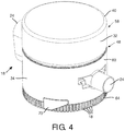
- FIGS. 3 and 4 illustrate external perspective views of humidification system 18 fully assembled.
- Canister 40 is seated in chamber dock 48 to permit the flow of liquid from liquid storage chamber 32 into humidification chamber 36.
- the bottom side of humidification 18 is configured to mate securely and/or removably with the housing that houses pressure generator 14 (not shown in FIGS. 3 and 4 ).
- a set of teeth 57 are formed extending outward from the bottom of humidification system 18 to facilitate a stable docking with the housing the houses pressure generator (not shown in FIGS. 3 and 4 ).
- FIG. 5 illustrates an exploded view of humidification system 18.
- humidification system 18 includes a storage portion 58, a gas flow portion 60, a humidification portion 62, a docking portion 64, and/or other portions.
- Storage portion 58 includes canister 40, lid 42, and cylindrical protrusion 44. Storage portion 58 forms liquid storage chamber 32 and feed path 38.
- Gas flow portion 60 is formed having a generally cylindrical outer housing. Inlet 22 and outlet 24, and chamber dock 48 are formed by gas flow portion 60, and gas flow portion 60 cooperates with other components (e.g., humidification portion 62) to form flow path 16 and humidification chamber 34.
- chamber seat 52 is formed and the cylindrical walls of gas flow portion 60 form chamber guide members 50.
- An opening 66 is formed in chamber seat 52 through which cylindrical protrusion 44 of storage portion 58 extends when humidification system 18 is assembled.
- Gas flow portion 60 also forms feed path guide members 54, extending downward in the view shown in FIG. 5 from opening 66.
- Gas flow portion 60 further includes locking members 68 and 70.
- Locking members 68 are formed at chamber dock 48 as protrusions inward from chamber guide members 50. Locking members 68 are configured to securely engage corresponding slots 72 formed on storage portion 58 to securely and removably affix storage portion 58 to gas flow portion 60. Locking members 70 are formed on the exterior of gas flow portion 60, and are configured to securely and removably mate with corresponding structures 74 formed on docking portion 64 to mate gas flow portion 60 to docking portion 64.
- Humidification portion 62 is configured to be seated inside gas flow portion 60 and docking portion 64. When humidification system 18 is assembled, humidification portion 62 cooperates with other components of humidification system 18 to form flow path 16 and humidification chamber 34. Humidification portion 62 is configured to carry heater 36.
- Docking portion 64 is configured to securely mate with gas flow portion 60 to hold humidification portion 62 in place within humidification system 18. Docking portion 64 is further configured (e.g. with teeth 57) to securely and removably dock humidification system 18 with the housing that houses pressure generator 14 (not shown in FIG. 5 ). Docking portion 64 is formed having an annular shape, such that humidification portion 62 extends therethrough when humidification system 18 is assembled (as can be seen in FIG. 2 ).
- FIGS. 6 and 7 show exploded views of storage portion 58.
- storage portion 58 includes canister 40, seal 76, path member 56, lid 42, valve 46, and/or other components.
- Canister 40 provides the volume in which liquid storage chamber 32 (not shown in FIGS. 6 and 7 ) is formed.
- Canister 40 has a generally cylindrical shape with an opening formed at one end.
- One or more locking members 78 are formed at the opening. Locking members 78 are configured to securely and removably engage corresponding slots 80 formed on lid 42.
- Seal 76 is configured to seal and engagement between canister 40 and lid 42.
- seal 76 is a typical, elastic o-ring seal that seals the engagement be being crushed between the sealed components.
- seal 76 is an annular seal having an inner slot 82 formed facing inward toward its center and an outer slot 84 facing outward from its outer periphery. Slots 82 and 84 are configured to receive components to further secure the seal provided by seal 76.
- outer slot 84 is configured to receive a protrusion 86 (shown in FIG. 7 ) formed at the opening of canister 40 to further secure the sealed engagement between canister 40 and seal 76.
- Path member 58 includes a feed path portion 88, an annular tab 90, and a path entrance portion 92.
- Feed path portion 88 is configured to extend into cylindrical protrusion 44 of lid 44 to form the serpentine route of feed path 38 (not shown in FIGS. 6 and 7 ).
- Annular tab 90 extends outward radially from feed path portion 88, and rests against lid 42 when storage portion 58 is assembled (e.g., as shown in FIG. 2 ).
- the edges of annular tab 90 are formed to fit inside of inner slot 84 of seal 76, thereby enhancing the sealed engagement between path member 58, seal 76, and lid 42 (e.g., as shown in FIG. 2 ).
- Path entrance portion 92 is formed as a hollow cylinder that extends out from annular tab 90 into the cavity of canister 40 in a direction opposite from feed path portion 88. At or near the interface between path entrance portion 92 and annular tab 90 a set of one or more feed path openings 94 are formed. Feed path openings 94 are formed having a size, shape, and/or arrangement on path entrance portions 92 that controls the flow of liquid into feed path 38 (not shown in FIGS. 6 and 7 ). As gas replacing the liquid leaving canister 40 flows up feed path 38 (not shown in FIGS. 6 and 7 ), the gas bypasses feed path openings 94 and continues up path entrance portion 92 and into canister 40. This may prevent disruptions in the consistency of the flow of liquid from canister 40 into path member 58 caused by gas flowing in the opposite direction.
- valve 46 is a plunger valve that includes a valve opening 96 and a plunger 98.
- Valve opening 96 is configured to be seated within hollow cylinder 44, and to receive plunger 98 therein.
- Plunger 98 is configured to close valve opening 96 if canister 40 is not installed in chamber dock 48 (not shown in FIGS. 6 and 7 ). Responsive to canister 40 being installed in chamber dock 48, plunger 98 is pushed back up into hollow cylinder 44, thereby enabling liquid and gas to flow through valve opening 96.
- FIG. 8 provides a sectional view of humidification system 18 that is similar to the view provided in FIG. 2 .
- humidification has been tilted with respect to horizontal by an angle ⁇ .
- FIGS. 2 and 8 illustrate the manner in which the serpentine shape of feed path 38 causes the flow of liquid out of liquid storage chamber 32 through feed path 38 to halt, responsive to humidification system 18 being moved out of an operational orientation.
- an "operational orientation” may include a range of tilt with respect to a base operating position.
- the base operating position is the position of device 10 when placed, bottom down, on a perfectly horizontal surface.
- an operational orientation may include orientations with less than about 20° of tilt form the base operating position.
- liquid from liquid storage chamber 32 spirals downward along feed path 38 due to gravity to replenish liquid that has been vaporized in the humidification chamber.
- air bubbles e.g. air bubble 100 spiral upward along feed path 38 and into liquid storage chamber 32 to replace the liquid that has left.
- the range of angles over which the humidification system can be tilted from the based orientation base operating position without halting the flow of fluid from the liquid storage chamber to the humidification chamber can be controlled based on the pitch of the helix.
- the present invention contemplates providing a selection of path members 56 having different pitches for the helix so that the user (or others) can select the at what angle the flow of fluid from the liquid storage chamber to the humidification chamber will be shut off.
- FIG. 9 illustrates a method 102 of preventing liquid ingress in a pressure support device configured to generate a pressurized flow of breathable gas for delivery to the airway of a subject.
- the pressurized flow of breathable gas is provided along a flow path within the device.
- the operations of method 102 presented below are intended to be illustrative. In some examples, method 102 may be accomplished with one or more additional operations not described, and/or without one or more of the operations discussed. Additionally, the order in which the operations of method 102 are illustrated in FIG. 9 and described below is not intended to be limiting.
- operation 104 responsive to the device having an operational orientation, liquid is fed from a liquid storage chamber into a humidification chamber through a feed path by gravity.
- the humidification chamber is disposed in the flow path through the device.
- the feed path has a serpentine shape.
- operation 104 is performed by a liquid storage chamber, a humidification chamber, and a feed path that are similar to or the same as liquid storage chamber 32, humidification chamber 34, and/or feed path 38 (shown in FIGS. 1-8 and described above).
- operation 106 liquid within the humidification chamber is heated such that the pressurized flow of breathable gas is humidified as it flows through the humidification chamber by vaporized liquid.
- operation 62 is performed by a heater similar to or the same as heater 36 (shown in FIGS. 1 and 2 , and described above).
- the flow of liquid from the liquid storage chamber into the humidification chamber is halted.
- the halting of the flow of liquid from the liquid storage chamber into the humidification chamber is halted by virtue of the serpentine shape of the feed path.
- any reference signs placed between parentheses shall not be construed as limiting the claim.
- the word “comprising” or “including” does not exclude the presence of elements or steps other than those listed in a claim.
- several of these means may be embodied by one and the same item of hardware.
- the word “a” or “an” preceding an element does not exclude the presence of a plurality of such elements.
- any device claim enumerating several means several of these means may be embodied by one and the same item of hardware.
- the mere fact that certain elements are recited in mutually different dependent claims does not indicate that these elements cannot be used in combination.
- several of these means may be embodied by one and the same item of hardware.
- the mere fact that certain elements are recited in mutually different dependent claims does not indicate that these elements cannot be used in combination.
Landscapes
- Health & Medical Sciences (AREA)
- Emergency Medicine (AREA)
- Pulmonology (AREA)
- Engineering & Computer Science (AREA)
- Anesthesiology (AREA)
- Biomedical Technology (AREA)
- Heart & Thoracic Surgery (AREA)
- Hematology (AREA)
- Life Sciences & Earth Sciences (AREA)
- Animal Behavior & Ethology (AREA)
- General Health & Medical Sciences (AREA)
- Public Health (AREA)
- Veterinary Medicine (AREA)
- Air Humidification (AREA)
Claims (6)
- Druckunterstützungssystem (10), Folgendes umfassend:einen Druckgenerator (14), der konfiguriert ist, um eine unter Druck stehende Strömung eines atembaren Gases zur Abgabe in den Atemweg eines Patienten zu erzeugen, wobei die unter Druck stehende Strömung eines atembaren Gases durch einen Strömungspfad (16) innerhalb des Systems (10) bereitgestellt wird;eine Flüssigkeitsvorratskammer (32), die konfiguriert ist, um eine Menge an Flüssigkeit zu halten;eine Befeuchtungskammer (34), die im Strömungspfad (16) angeordnet ist, wobei die Befeuchtungskammer (34) konfiguriert ist, um Flüssigkeit aus der Flüssigkeitsvorratskammer (32) zu empfangen; undeinen Zuführpfads (38), der derart konfiguriert ist, dass als Reaktion darauf, dass das System (10) eine operative Ausrichtung hat, Flüssigkeit aus der Flüssigkeitsvorratskammer (32) durch den Zuführpfad (38) durch die Schwerkraft zur Befeuchtungskammer (34) zugeführt wird, wobei der Zuführpfad (38) eine Serpentinenform aufweist, sodass, als Reaktion darauf, dass das System (10) die operative Ausrichtung verlassen hat, die Flüssigkeitsströmung aus der Flüssigkeitsvorratskammer (32) zur Befeuchtungskammer (34) angehalten wird.
- System (10) nach Anspruch 1, wobei die Serpentinenform des Zuführpfads (38) eine wendelförmige Form umfasst.
- System (10) nach Anspruch 2, wobei die wendelförmige Form innerhalb des Zuführpfads (38) durch ein wendeiförmiges Element gebildet wird, das im Zuführpfad (38) angeordnet ist.
- System (10) nach Anspruch 1, wobei die Flüssigkeitsvorratskammer (32) eine mit Ausnahme des Zuführpfads (38) versiegelte Kammer ist, und wobei die Serpentinenform des Zuführpfads (38) die Flüssigkeitsströmung von der Flüssigkeitskammer zur Befeuchtungskammer (34) durch Einfangen von Luft innerhalb des Zuführpfads (38) anhält, welche die Flüssigkeitsströmung blockiert.
- System (10) nach Anspruch 1, wobei die operative Ausrichtung Drehausrichtungen des Systems (10) umfasst, die eine Geräteneigung von weniger als zwanzig Grad aufweisen.
- System nach Anspruch 1, darüber hinaus eine Heizung (36) umfassend, die konfiguriert ist, um die Flüssigkeit innerhalb der Befeuchtungskammer (34) zu erwärmen, sodass die unter Druck stehende Strömung eines atembaren Gases befeuchtet wird, wenn sie durch die Befeuchtungskammer strömt.
Applications Claiming Priority (2)
| Application Number | Priority Date | Filing Date | Title |
|---|---|---|---|
| US201161452193P | 2011-03-14 | 2011-03-14 | |
| PCT/IB2012/051041 WO2012123854A1 (en) | 2011-03-14 | 2012-03-06 | Humidifier with liquid ingress protection |
Publications (2)
| Publication Number | Publication Date |
|---|---|
| EP2686053A1 EP2686053A1 (de) | 2014-01-22 |
| EP2686053B1 true EP2686053B1 (de) | 2017-05-17 |
Family
ID=45852632
Family Applications (1)
| Application Number | Title | Priority Date | Filing Date |
|---|---|---|---|
| EP12709384.7A Not-in-force EP2686053B1 (de) | 2011-03-14 | 2012-03-06 | Befeuchter mit flüssigkeitseindringungsschutz |
Country Status (5)
| Country | Link |
|---|---|
| US (1) | US9545492B2 (de) |
| EP (1) | EP2686053B1 (de) |
| JP (1) | JP6002696B2 (de) |
| CN (1) | CN103429293B (de) |
| WO (1) | WO2012123854A1 (de) |
Families Citing this family (12)
| Publication number | Priority date | Publication date | Assignee | Title |
|---|---|---|---|---|
| US10314989B2 (en) | 2013-01-28 | 2019-06-11 | Hancock Medical, Inc. | Position control devices and methods for use with positive airway pressure systems |
| EP2837399B1 (de) * | 2013-08-13 | 2016-08-17 | Apex Medical Corp. | Flüssigkeitsbehälter zur Gasbefeuchtung und Flüssigkeitslagervorrichtung |
| US9155858B2 (en) | 2013-08-20 | 2015-10-13 | Apex Medical Corp. | Liquid container for gas humidification and liquid storage device |
| CN103800982B (zh) * | 2014-01-08 | 2015-12-23 | 北京怡和嘉业医疗科技有限公司 | 用于呼吸机的加湿器以及呼吸机 |
| SG10201907307SA (en) * | 2014-01-30 | 2019-09-27 | Fisher & Paykel Healthcare Ltd | Breathing assistance apparatus with liquid containment |
| WO2016028525A1 (en) * | 2014-08-18 | 2016-02-25 | Hancock Medical, Inc. | Portable pap device with humidification |
| CN104548299B (zh) * | 2015-01-09 | 2017-05-24 | 北京怡和嘉业医疗科技有限公司 | 一种呼吸机及湿化器 |
| CN104548307B (zh) | 2015-01-09 | 2017-12-22 | 北京怡和嘉业医疗科技股份有限公司 | 一种加湿装置、湿化器及呼吸机 |
| USD776802S1 (en) | 2015-03-06 | 2017-01-17 | Hancock Medical, Inc. | Positive airway pressure system console |
| CN104941047B (zh) * | 2015-07-02 | 2017-08-15 | 刘黎 | 一种加湿器和持续正压通气治疗机 |
| JP2019518520A (ja) | 2016-05-19 | 2019-07-04 | ハンコック メディカル, インコーポレイテッド | 位置閉塞性睡眠時無呼吸検出システム |
| JP7263261B2 (ja) | 2017-06-08 | 2023-04-24 | ケース ウエスタン リザーブ ユニバーシティ | 制御された濃度で送達を行うための気化システム |
Family Cites Families (26)
| Publication number | Priority date | Publication date | Assignee | Title |
|---|---|---|---|---|
| US3804280A (en) | 1971-07-27 | 1974-04-16 | Respiratory Care | Multi-use inhalation therapy apparatus |
| US4051205A (en) * | 1972-09-13 | 1977-09-27 | Graham Cameron Grant | Apparatus for saturated gas delivery |
| GB1448473A (en) * | 1972-09-13 | 1976-09-08 | Grant G C | Vapour saturated gas delivery |
| JPS5833467Y2 (ja) * | 1978-08-24 | 1983-07-26 | 日本特殊陶業株式会社 | 超音波加湿装置 |
| DE3574344D1 (en) * | 1984-08-29 | 1989-12-28 | Omron Tateisi Electronics Co | Ultrasonic atomizer |
| JPS6168159A (ja) * | 1984-09-10 | 1986-04-08 | Omron Tateisi Electronics Co | 超音波霧化器 |
| JPH0512896A (ja) | 1991-07-08 | 1993-01-22 | Sharp Corp | 音声録音再生装置 |
| US5579758A (en) | 1994-07-13 | 1996-12-03 | Century; Theodore J. | Sub-miniature aerosolizer with helical flow path formed by threaded insert |
| FI102145B (fi) | 1995-12-29 | 1998-10-30 | Instrumentarium Oy | Sovitelma anestesianestesäiliön täytön rajoittamiseksi |
| DE29617077U1 (de) | 1996-10-01 | 1997-01-09 | Drägerwerk AG, 23558 Lübeck | Anfeuchtersystem mit einer Füllstandsregelung für die zu verdampfende Flüssigkeit |
| JP3436462B2 (ja) | 1996-11-01 | 2003-08-11 | 三菱電機株式会社 | 半導体装置 |
| US5916493A (en) * | 1997-08-12 | 1999-06-29 | Pegasus Research Corporation | Humidifier system |
| JPH11197553A (ja) | 1998-01-09 | 1999-07-27 | Calsonic Corp | 霧化装置 |
| US6398197B1 (en) * | 1999-05-10 | 2002-06-04 | Fisher & Paykel Limited | Water chamber |
| DE20010553U1 (de) * | 2000-06-19 | 2000-11-23 | Hoffrichter, Helmut, 19061 Schwerin | Luftbefeuchter für ein Beatmungsgerät |
| US6827340B2 (en) * | 2000-08-14 | 2004-12-07 | Taga Medical Technologies, Inc. | CPAP humidifier |
| WO2002066106A1 (en) * | 2001-02-16 | 2002-08-29 | Resmed Limited | Humidifier with structure to prevent backflow of liquid through the humidifier inlet |
| DE10234811C1 (de) * | 2002-07-31 | 2003-11-27 | Draeger Medical Ag | Atemgasanfeuchtersystem für einen Patienten |
| US6749181B1 (en) | 2002-11-21 | 2004-06-15 | Fong Yen Electrical Co., Ltd. | Humidifier |
| AU2003903139A0 (en) | 2003-06-20 | 2003-07-03 | Resmed Limited | Breathable gas apparatus with humidifier |
| EP1924312B1 (de) | 2005-08-15 | 2016-06-29 | ResMed Limited | Befeuchter-wanne für ein cpap-gerät |
| US8997740B2 (en) | 2005-09-27 | 2015-04-07 | Ric Investments, Llc | Humidifier with back-flow prevention valve |
| JP5009989B2 (ja) | 2006-08-25 | 2012-08-29 | フィッシャー アンド ペイケル ヘルスケア リミテッド | 内部発熱体及びヒータープレートを備えた加湿器 |
| WO2009001621A1 (ja) | 2007-06-26 | 2008-12-31 | Murata Manufacturing Co., Ltd. | 部品内蔵基板の製造方法 |
| US8424519B2 (en) | 2009-05-06 | 2013-04-23 | A Plus Medical | Positive airway pressure apparatus |
| JP5532946B2 (ja) | 2010-01-18 | 2014-06-25 | セイコーエプソン株式会社 | 印刷装置における印刷条件設定方法 |
-
2012
- 2012-03-06 CN CN201280013174.0A patent/CN103429293B/zh not_active Expired - Fee Related
- 2012-03-06 EP EP12709384.7A patent/EP2686053B1/de not_active Not-in-force
- 2012-03-06 JP JP2013558539A patent/JP6002696B2/ja not_active Expired - Fee Related
- 2012-03-06 US US14/004,918 patent/US9545492B2/en active Active
- 2012-03-06 WO PCT/IB2012/051041 patent/WO2012123854A1/en not_active Ceased
Also Published As
| Publication number | Publication date |
|---|---|
| WO2012123854A1 (en) | 2012-09-20 |
| EP2686053A1 (de) | 2014-01-22 |
| CN103429293B (zh) | 2016-02-24 |
| CN103429293A (zh) | 2013-12-04 |
| US20140000600A1 (en) | 2014-01-02 |
| JP6002696B2 (ja) | 2016-10-05 |
| US9545492B2 (en) | 2017-01-17 |
| JP2014512898A (ja) | 2014-05-29 |
Similar Documents
| Publication | Publication Date | Title |
|---|---|---|
| EP2686053B1 (de) | Befeuchter mit flüssigkeitseindringungsschutz | |
| US11819623B2 (en) | Positive airway pressure device | |
| EP2313140B1 (de) | Befeuchter für ein beatmungssystem | |
| AU2009219787B2 (en) | Pressure support system with upstream humidifier | |
| US9174016B2 (en) | Humidifier for a breathing system | |
| EP2519298B1 (de) | Feuchtigkeitskontrolle in einem druckunterstützungssystem | |
| EP2608836B1 (de) | Tragbares befeuchtungssystem und adapter dafür | |
| JP2005538817A (ja) | 加湿器用水充填装置 | |
| EP3590571B1 (de) | Beatmungsvorrichtung mit flüssigkeitsbehälter | |
| EP3880283B1 (de) | Druckunterstützungssystemventil | |
| EP4294487B1 (de) | Integrierter befeuchter mit wassereintrittsschutz | |
| US12285568B2 (en) | Humidification device and respiratory humidification and blowing apparatus including the same | |
| CN102671275B (zh) | 加湿设备和具有该加湿设备的通气治疗设备 | |
| CN202654514U (zh) | 加湿设备和具有该加湿设备的通气治疗设备 |
Legal Events
| Date | Code | Title | Description |
|---|---|---|---|
| PUAI | Public reference made under article 153(3) epc to a published international application that has entered the european phase |
Free format text: ORIGINAL CODE: 0009012 |
|
| 17P | Request for examination filed |
Effective date: 20131014 |
|
| AK | Designated contracting states |
Kind code of ref document: A1 Designated state(s): AL AT BE BG CH CY CZ DE DK EE ES FI FR GB GR HR HU IE IS IT LI LT LU LV MC MK MT NL NO PL PT RO RS SE SI SK SM TR |
|
| DAX | Request for extension of the european patent (deleted) | ||
| 17Q | First examination report despatched |
Effective date: 20151023 |
|
| GRAP | Despatch of communication of intention to grant a patent |
Free format text: ORIGINAL CODE: EPIDOSNIGR1 |
|
| INTG | Intention to grant announced |
Effective date: 20161213 |
|
| RIN1 | Information on inventor provided before grant (corrected) |
Inventor name: DIMATTEO, MARK, WILLIAM Inventor name: BARCLAY, MARK |
|
| GRAS | Grant fee paid |
Free format text: ORIGINAL CODE: EPIDOSNIGR3 |
|
| GRAA | (expected) grant |
Free format text: ORIGINAL CODE: 0009210 |
|
| AK | Designated contracting states |
Kind code of ref document: B1 Designated state(s): AL AT BE BG CH CY CZ DE DK EE ES FI FR GB GR HR HU IE IS IT LI LT LU LV MC MK MT NL NO PL PT RO RS SE SI SK SM TR |
|
| REG | Reference to a national code |
Ref country code: GB Ref legal event code: FG4D |
|
| REG | Reference to a national code |
Ref country code: CH Ref legal event code: EP |
|
| REG | Reference to a national code |
Ref country code: IE Ref legal event code: FG4D |
|
| REG | Reference to a national code |
Ref country code: AT Ref legal event code: REF Ref document number: 893913 Country of ref document: AT Kind code of ref document: T Effective date: 20170615 |
|
| REG | Reference to a national code |
Ref country code: DE Ref legal event code: R096 Ref document number: 602012032521 Country of ref document: DE |
|
| REG | Reference to a national code |
Ref country code: NL Ref legal event code: MP Effective date: 20170517 |
|
| REG | Reference to a national code |
Ref country code: LT Ref legal event code: MG4D |
|
| REG | Reference to a national code |
Ref country code: AT Ref legal event code: MK05 Ref document number: 893913 Country of ref document: AT Kind code of ref document: T Effective date: 20170517 |
|
| PG25 | Lapsed in a contracting state [announced via postgrant information from national office to epo] |
Ref country code: ES Free format text: LAPSE BECAUSE OF FAILURE TO SUBMIT A TRANSLATION OF THE DESCRIPTION OR TO PAY THE FEE WITHIN THE PRESCRIBED TIME-LIMIT Effective date: 20170517 Ref country code: HR Free format text: LAPSE BECAUSE OF FAILURE TO SUBMIT A TRANSLATION OF THE DESCRIPTION OR TO PAY THE FEE WITHIN THE PRESCRIBED TIME-LIMIT Effective date: 20170517 Ref country code: AT Free format text: LAPSE BECAUSE OF FAILURE TO SUBMIT A TRANSLATION OF THE DESCRIPTION OR TO PAY THE FEE WITHIN THE PRESCRIBED TIME-LIMIT Effective date: 20170517 Ref country code: LT Free format text: LAPSE BECAUSE OF FAILURE TO SUBMIT A TRANSLATION OF THE DESCRIPTION OR TO PAY THE FEE WITHIN THE PRESCRIBED TIME-LIMIT Effective date: 20170517 Ref country code: GR Free format text: LAPSE BECAUSE OF FAILURE TO SUBMIT A TRANSLATION OF THE DESCRIPTION OR TO PAY THE FEE WITHIN THE PRESCRIBED TIME-LIMIT Effective date: 20170818 Ref country code: NO Free format text: LAPSE BECAUSE OF FAILURE TO SUBMIT A TRANSLATION OF THE DESCRIPTION OR TO PAY THE FEE WITHIN THE PRESCRIBED TIME-LIMIT Effective date: 20170817 Ref country code: FI Free format text: LAPSE BECAUSE OF FAILURE TO SUBMIT A TRANSLATION OF THE DESCRIPTION OR TO PAY THE FEE WITHIN THE PRESCRIBED TIME-LIMIT Effective date: 20170517 |
|
| PG25 | Lapsed in a contracting state [announced via postgrant information from national office to epo] |
Ref country code: PL Free format text: LAPSE BECAUSE OF FAILURE TO SUBMIT A TRANSLATION OF THE DESCRIPTION OR TO PAY THE FEE WITHIN THE PRESCRIBED TIME-LIMIT Effective date: 20170517 Ref country code: IS Free format text: LAPSE BECAUSE OF FAILURE TO SUBMIT A TRANSLATION OF THE DESCRIPTION OR TO PAY THE FEE WITHIN THE PRESCRIBED TIME-LIMIT Effective date: 20170917 Ref country code: RS Free format text: LAPSE BECAUSE OF FAILURE TO SUBMIT A TRANSLATION OF THE DESCRIPTION OR TO PAY THE FEE WITHIN THE PRESCRIBED TIME-LIMIT Effective date: 20170517 Ref country code: BG Free format text: LAPSE BECAUSE OF FAILURE TO SUBMIT A TRANSLATION OF THE DESCRIPTION OR TO PAY THE FEE WITHIN THE PRESCRIBED TIME-LIMIT Effective date: 20170817 Ref country code: SE Free format text: LAPSE BECAUSE OF FAILURE TO SUBMIT A TRANSLATION OF THE DESCRIPTION OR TO PAY THE FEE WITHIN THE PRESCRIBED TIME-LIMIT Effective date: 20170517 Ref country code: LV Free format text: LAPSE BECAUSE OF FAILURE TO SUBMIT A TRANSLATION OF THE DESCRIPTION OR TO PAY THE FEE WITHIN THE PRESCRIBED TIME-LIMIT Effective date: 20170517 Ref country code: NL Free format text: LAPSE BECAUSE OF FAILURE TO SUBMIT A TRANSLATION OF THE DESCRIPTION OR TO PAY THE FEE WITHIN THE PRESCRIBED TIME-LIMIT Effective date: 20170517 |
|
| PG25 | Lapsed in a contracting state [announced via postgrant information from national office to epo] |
Ref country code: CZ Free format text: LAPSE BECAUSE OF FAILURE TO SUBMIT A TRANSLATION OF THE DESCRIPTION OR TO PAY THE FEE WITHIN THE PRESCRIBED TIME-LIMIT Effective date: 20170517 Ref country code: EE Free format text: LAPSE BECAUSE OF FAILURE TO SUBMIT A TRANSLATION OF THE DESCRIPTION OR TO PAY THE FEE WITHIN THE PRESCRIBED TIME-LIMIT Effective date: 20170517 Ref country code: DK Free format text: LAPSE BECAUSE OF FAILURE TO SUBMIT A TRANSLATION OF THE DESCRIPTION OR TO PAY THE FEE WITHIN THE PRESCRIBED TIME-LIMIT Effective date: 20170517 Ref country code: SK Free format text: LAPSE BECAUSE OF FAILURE TO SUBMIT A TRANSLATION OF THE DESCRIPTION OR TO PAY THE FEE WITHIN THE PRESCRIBED TIME-LIMIT Effective date: 20170517 Ref country code: RO Free format text: LAPSE BECAUSE OF FAILURE TO SUBMIT A TRANSLATION OF THE DESCRIPTION OR TO PAY THE FEE WITHIN THE PRESCRIBED TIME-LIMIT Effective date: 20170517 |
|
| REG | Reference to a national code |
Ref country code: DE Ref legal event code: R097 Ref document number: 602012032521 Country of ref document: DE |
|
| PG25 | Lapsed in a contracting state [announced via postgrant information from national office to epo] |
Ref country code: SM Free format text: LAPSE BECAUSE OF FAILURE TO SUBMIT A TRANSLATION OF THE DESCRIPTION OR TO PAY THE FEE WITHIN THE PRESCRIBED TIME-LIMIT Effective date: 20170517 Ref country code: IT Free format text: LAPSE BECAUSE OF FAILURE TO SUBMIT A TRANSLATION OF THE DESCRIPTION OR TO PAY THE FEE WITHIN THE PRESCRIBED TIME-LIMIT Effective date: 20170517 |
|
| PLBE | No opposition filed within time limit |
Free format text: ORIGINAL CODE: 0009261 |
|
| STAA | Information on the status of an ep patent application or granted ep patent |
Free format text: STATUS: NO OPPOSITION FILED WITHIN TIME LIMIT |
|
| REG | Reference to a national code |
Ref country code: FR Ref legal event code: PLFP Year of fee payment: 7 |
|
| 26N | No opposition filed |
Effective date: 20180220 |
|
| PG25 | Lapsed in a contracting state [announced via postgrant information from national office to epo] |
Ref country code: SI Free format text: LAPSE BECAUSE OF FAILURE TO SUBMIT A TRANSLATION OF THE DESCRIPTION OR TO PAY THE FEE WITHIN THE PRESCRIBED TIME-LIMIT Effective date: 20170517 |
|
| REG | Reference to a national code |
Ref country code: CH Ref legal event code: PL |
|
| GBPC | Gb: european patent ceased through non-payment of renewal fee |
Effective date: 20180306 |
|
| PG25 | Lapsed in a contracting state [announced via postgrant information from national office to epo] |
Ref country code: MC Free format text: LAPSE BECAUSE OF FAILURE TO SUBMIT A TRANSLATION OF THE DESCRIPTION OR TO PAY THE FEE WITHIN THE PRESCRIBED TIME-LIMIT Effective date: 20170517 |
|
| REG | Reference to a national code |
Ref country code: BE Ref legal event code: MM Effective date: 20180331 |
|
| REG | Reference to a national code |
Ref country code: IE Ref legal event code: MM4A |
|
| PG25 | Lapsed in a contracting state [announced via postgrant information from national office to epo] |
Ref country code: LU Free format text: LAPSE BECAUSE OF NON-PAYMENT OF DUE FEES Effective date: 20180306 |
|
| PG25 | Lapsed in a contracting state [announced via postgrant information from national office to epo] |
Ref country code: IE Free format text: LAPSE BECAUSE OF NON-PAYMENT OF DUE FEES Effective date: 20180306 |
|
| PG25 | Lapsed in a contracting state [announced via postgrant information from national office to epo] |
Ref country code: LI Free format text: LAPSE BECAUSE OF NON-PAYMENT OF DUE FEES Effective date: 20180331 Ref country code: GB Free format text: LAPSE BECAUSE OF NON-PAYMENT OF DUE FEES Effective date: 20180306 Ref country code: BE Free format text: LAPSE BECAUSE OF NON-PAYMENT OF DUE FEES Effective date: 20180331 Ref country code: CH Free format text: LAPSE BECAUSE OF NON-PAYMENT OF DUE FEES Effective date: 20180331 |
|
| PG25 | Lapsed in a contracting state [announced via postgrant information from national office to epo] |
Ref country code: MT Free format text: LAPSE BECAUSE OF NON-PAYMENT OF DUE FEES Effective date: 20180306 |
|
| PG25 | Lapsed in a contracting state [announced via postgrant information from national office to epo] |
Ref country code: TR Free format text: LAPSE BECAUSE OF FAILURE TO SUBMIT A TRANSLATION OF THE DESCRIPTION OR TO PAY THE FEE WITHIN THE PRESCRIBED TIME-LIMIT Effective date: 20170517 |
|
| PG25 | Lapsed in a contracting state [announced via postgrant information from national office to epo] |
Ref country code: HU Free format text: LAPSE BECAUSE OF FAILURE TO SUBMIT A TRANSLATION OF THE DESCRIPTION OR TO PAY THE FEE WITHIN THE PRESCRIBED TIME-LIMIT; INVALID AB INITIO Effective date: 20120306 Ref country code: PT Free format text: LAPSE BECAUSE OF FAILURE TO SUBMIT A TRANSLATION OF THE DESCRIPTION OR TO PAY THE FEE WITHIN THE PRESCRIBED TIME-LIMIT Effective date: 20170517 |
|
| PG25 | Lapsed in a contracting state [announced via postgrant information from national office to epo] |
Ref country code: CY Free format text: LAPSE BECAUSE OF FAILURE TO SUBMIT A TRANSLATION OF THE DESCRIPTION OR TO PAY THE FEE WITHIN THE PRESCRIBED TIME-LIMIT Effective date: 20170517 Ref country code: MK Free format text: LAPSE BECAUSE OF NON-PAYMENT OF DUE FEES Effective date: 20170517 |
|
| PG25 | Lapsed in a contracting state [announced via postgrant information from national office to epo] |
Ref country code: AL Free format text: LAPSE BECAUSE OF FAILURE TO SUBMIT A TRANSLATION OF THE DESCRIPTION OR TO PAY THE FEE WITHIN THE PRESCRIBED TIME-LIMIT Effective date: 20170517 |
|
| PGFP | Annual fee paid to national office [announced via postgrant information from national office to epo] |
Ref country code: FR Payment date: 20230323 Year of fee payment: 12 |
|
| PGFP | Annual fee paid to national office [announced via postgrant information from national office to epo] |
Ref country code: DE Payment date: 20220628 Year of fee payment: 12 |
|
| REG | Reference to a national code |
Ref country code: DE Ref legal event code: R119 Ref document number: 602012032521 Country of ref document: DE |
|
| PG25 | Lapsed in a contracting state [announced via postgrant information from national office to epo] |
Ref country code: DE Free format text: LAPSE BECAUSE OF NON-PAYMENT OF DUE FEES Effective date: 20241001 |
|
| PG25 | Lapsed in a contracting state [announced via postgrant information from national office to epo] |
Ref country code: FR Free format text: LAPSE BECAUSE OF NON-PAYMENT OF DUE FEES Effective date: 20240331 |
|
| PG25 | Lapsed in a contracting state [announced via postgrant information from national office to epo] |
Ref country code: FR Free format text: LAPSE BECAUSE OF NON-PAYMENT OF DUE FEES Effective date: 20240331 Ref country code: DE Free format text: LAPSE BECAUSE OF NON-PAYMENT OF DUE FEES Effective date: 20241001 |