EP2686087B2 - Verfahren und vorrichtung zur entfernung von hitzestabilen aminsalzen aus einem aminabsorbens - Google Patents
Verfahren und vorrichtung zur entfernung von hitzestabilen aminsalzen aus einem aminabsorbens Download PDFInfo
- Publication number
- EP2686087B2 EP2686087B2 EP12712467.5A EP12712467A EP2686087B2 EP 2686087 B2 EP2686087 B2 EP 2686087B2 EP 12712467 A EP12712467 A EP 12712467A EP 2686087 B2 EP2686087 B2 EP 2686087B2
- Authority
- EP
- European Patent Office
- Prior art keywords
- absorbent
- amine
- amine absorbent
- lean
- residual
- Prior art date
- Legal status (The legal status is an assumption and is not a legal conclusion. Google has not performed a legal analysis and makes no representation as to the accuracy of the status listed.)
- Active
Links
Images
Classifications
-
- B—PERFORMING OPERATIONS; TRANSPORTING
- B01—PHYSICAL OR CHEMICAL PROCESSES OR APPARATUS IN GENERAL
- B01D—SEPARATION
- B01D53/00—Separation of gases or vapours; Recovering vapours of volatile solvents from gases; Chemical or biological purification of waste gases, e.g. engine exhaust gases, smoke, fumes, flue gases, aerosols
- B01D53/14—Separation of gases or vapours; Recovering vapours of volatile solvents from gases; Chemical or biological purification of waste gases, e.g. engine exhaust gases, smoke, fumes, flue gases, aerosols by absorption
- B01D53/1425—Regeneration of liquid absorbents
-
- B—PERFORMING OPERATIONS; TRANSPORTING
- B01—PHYSICAL OR CHEMICAL PROCESSES OR APPARATUS IN GENERAL
- B01D—SEPARATION
- B01D53/00—Separation of gases or vapours; Recovering vapours of volatile solvents from gases; Chemical or biological purification of waste gases, e.g. engine exhaust gases, smoke, fumes, flue gases, aerosols
- B01D53/14—Separation of gases or vapours; Recovering vapours of volatile solvents from gases; Chemical or biological purification of waste gases, e.g. engine exhaust gases, smoke, fumes, flue gases, aerosols by absorption
- B01D53/1456—Removing acid components
- B01D53/1475—Removing carbon dioxide
-
- B—PERFORMING OPERATIONS; TRANSPORTING
- B01—PHYSICAL OR CHEMICAL PROCESSES OR APPARATUS IN GENERAL
- B01D—SEPARATION
- B01D53/00—Separation of gases or vapours; Recovering vapours of volatile solvents from gases; Chemical or biological purification of waste gases, e.g. engine exhaust gases, smoke, fumes, flue gases, aerosols
- B01D53/14—Separation of gases or vapours; Recovering vapours of volatile solvents from gases; Chemical or biological purification of waste gases, e.g. engine exhaust gases, smoke, fumes, flue gases, aerosols by absorption
- B01D53/1493—Selection of liquid materials for use as absorbents
-
- B—PERFORMING OPERATIONS; TRANSPORTING
- B01—PHYSICAL OR CHEMICAL PROCESSES OR APPARATUS IN GENERAL
- B01D—SEPARATION
- B01D61/00—Processes of separation using semi-permeable membranes, e.g. dialysis, osmosis or ultrafiltration; Apparatus, accessories or auxiliary operations specially adapted therefor
- B01D61/42—Electrodialysis; Electro-osmosis ; Electro-ultrafiltration; Membrane capacitive deionization
- B01D61/422—Electrodialysis
-
- B—PERFORMING OPERATIONS; TRANSPORTING
- B01—PHYSICAL OR CHEMICAL PROCESSES OR APPARATUS IN GENERAL
- B01J—CHEMICAL OR PHYSICAL PROCESSES, e.g. CATALYSIS OR COLLOID CHEMISTRY; THEIR RELEVANT APPARATUS
- B01J47/00—Ion-exchange processes in general; Apparatus therefor
-
- C—CHEMISTRY; METALLURGY
- C07—ORGANIC CHEMISTRY
- C07C—ACYCLIC OR CARBOCYCLIC COMPOUNDS
- C07C209/00—Preparation of compounds containing amino groups bound to a carbon skeleton
- C07C209/82—Purification; Separation; Stabilisation; Use of additives
- C07C209/84—Purification
-
- B—PERFORMING OPERATIONS; TRANSPORTING
- B01—PHYSICAL OR CHEMICAL PROCESSES OR APPARATUS IN GENERAL
- B01D—SEPARATION
- B01D2252/00—Absorbents, i.e. solvents and liquid materials for gas absorption
- B01D2252/20—Organic absorbents
- B01D2252/204—Amines
-
- B—PERFORMING OPERATIONS; TRANSPORTING
- B01—PHYSICAL OR CHEMICAL PROCESSES OR APPARATUS IN GENERAL
- B01D—SEPARATION
- B01D2252/00—Absorbents, i.e. solvents and liquid materials for gas absorption
- B01D2252/20—Organic absorbents
- B01D2252/204—Amines
- B01D2252/20478—Alkanolamines
- B01D2252/20484—Alkanolamines with one hydroxyl group
-
- B—PERFORMING OPERATIONS; TRANSPORTING
- B01—PHYSICAL OR CHEMICAL PROCESSES OR APPARATUS IN GENERAL
- B01D—SEPARATION
- B01D2252/00—Absorbents, i.e. solvents and liquid materials for gas absorption
- B01D2252/20—Organic absorbents
- B01D2252/204—Amines
- B01D2252/20478—Alkanolamines
- B01D2252/20489—Alkanolamines with two or more hydroxyl groups
-
- B—PERFORMING OPERATIONS; TRANSPORTING
- B01—PHYSICAL OR CHEMICAL PROCESSES OR APPARATUS IN GENERAL
- B01D—SEPARATION
- B01D2257/00—Components to be removed
- B01D2257/50—Carbon oxides
- B01D2257/504—Carbon dioxide
-
- B—PERFORMING OPERATIONS; TRANSPORTING
- B01—PHYSICAL OR CHEMICAL PROCESSES OR APPARATUS IN GENERAL
- B01D—SEPARATION
- B01D2258/00—Sources of waste gases
- B01D2258/02—Other waste gases
- B01D2258/0283—Flue gases
-
- B—PERFORMING OPERATIONS; TRANSPORTING
- B01—PHYSICAL OR CHEMICAL PROCESSES OR APPARATUS IN GENERAL
- B01D—SEPARATION
- B01D2259/00—Type of treatment
- B01D2259/40—Further details for adsorption processes and devices
- B01D2259/40083—Regeneration of adsorbents in processes other than pressure or temperature swing adsorption
- B01D2259/40088—Regeneration of adsorbents in processes other than pressure or temperature swing adsorption by heating
- B01D2259/4009—Regeneration of adsorbents in processes other than pressure or temperature swing adsorption by heating using hot gas
-
- Y—GENERAL TAGGING OF NEW TECHNOLOGICAL DEVELOPMENTS; GENERAL TAGGING OF CROSS-SECTIONAL TECHNOLOGIES SPANNING OVER SEVERAL SECTIONS OF THE IPC; TECHNICAL SUBJECTS COVERED BY FORMER USPC CROSS-REFERENCE ART COLLECTIONS [XRACs] AND DIGESTS
- Y02—TECHNOLOGIES OR APPLICATIONS FOR MITIGATION OR ADAPTATION AGAINST CLIMATE CHANGE
- Y02A—TECHNOLOGIES FOR ADAPTATION TO CLIMATE CHANGE
- Y02A50/00—TECHNOLOGIES FOR ADAPTATION TO CLIMATE CHANGE in human health protection, e.g. against extreme weather
- Y02A50/20—Air quality improvement or preservation, e.g. vehicle emission control or emission reduction by using catalytic converters
-
- Y—GENERAL TAGGING OF NEW TECHNOLOGICAL DEVELOPMENTS; GENERAL TAGGING OF CROSS-SECTIONAL TECHNOLOGIES SPANNING OVER SEVERAL SECTIONS OF THE IPC; TECHNICAL SUBJECTS COVERED BY FORMER USPC CROSS-REFERENCE ART COLLECTIONS [XRACs] AND DIGESTS
- Y02—TECHNOLOGIES OR APPLICATIONS FOR MITIGATION OR ADAPTATION AGAINST CLIMATE CHANGE
- Y02C—CAPTURE, STORAGE, SEQUESTRATION OR DISPOSAL OF GREENHOUSE GASES [GHG]
- Y02C20/00—Capture or disposal of greenhouse gases
- Y02C20/40—Capture or disposal of greenhouse gases of CO2
Definitions
- the proposed invention relates to a system and a method for the removal of heat stable amine salts from an amine absorbent used in a carbon dioxide (CO 2 ) capture process.
- a hot process gas (or flue gas) is generated.
- a flue gas will often contain, among other things, carbon dioxide (CO 2 ).
- CO 2 carbon dioxide
- liquid solutions comprising amine compounds are commonly used as an absorbent.
- amine compounds commonly used in absorption of CO 2 from gas streams include monoethanolamine (MEA), diethanolamine (DEA), methyldiethanolamine (MDEA), diisopropylamine (DIPA) and aminoethoxyethanol (diglycolamine) (DGA).
- MEA monoethanolamine
- DEA diethanolamine
- MDEA methyldiethanolamine
- DIPA diisopropylamine
- DGA aminoethoxyethanol
- the most commonly used amines compounds in industrial plants are the alkanolamines MEA, DEA, and MDEA.
- CO 2 in the gas stream is captured in the liquid absorbent solution in an absorption process.
- a CO 2 absorber is employed to establish suitable conditions (temperature, pressure, turbulence, etc.) for chemical absorption of CO 2 into the amine absorbent from a mixed gas stream.
- the amine absorbent containing absorbed CO 2 is subsequently regenerated, whereby absorbed CO 2 is separated from the absorbent, and the regenerated absorbent is then reused in the CO 2 absorption process.
- a circulating absorbent stream is formed. Regeneration is generally achieved by heating the amine absorbent in a stripper reboiler to a temperature at which CO 2 is released from the absorbent.
- the absorbent In the regenerator reboiler the absorbent is subjected to high temperature (generally about 115 °C or higher), whereas in the absorber the absorbent is exposed to higher O 2 environment. As a result of the exposure to high temperature and/or the presence of O 2 , the amine solvent(s) of the absorbent may undergo degradation, whereby undesired degradation products are formed in the liquid phase. These degradation products, known as heat stable salts or heat stable amine salts (HSS), may accumulate in the circulating absorbent stream. The HSS reduce the CO 2 removal potency of the absorbent and may therefore preferably be removed from the absorbent stream.
- high temperature generally about 115 °C or higher
- O 2 environment As a result of the exposure to high temperature and/or the presence of O 2 , the amine solvent(s) of the absorbent may undergo degradation, whereby undesired degradation products are formed in the liquid phase. These degradation products, known as heat stable salts or heat stable amine salts (HSS), may accumulate in the
- a common method of HSS removal is to take a slipstream from the circulating absorbent, separate the bulk absorbent from the HSS in a reclaimer and recycle the separated amine back to the circulating absorbent loop as reclaimed absorbent.
- a reclaimer can consist of a distillation, ion exchange, or electrodialysis unit (see, for instance, EP1216744 ).
- HSS heat stable salts
- a separation step e.g. electrodialysis (ED)
- ED electrodialysis
- Amine based CO 2 capture systems are sometimes operated in a way such that a relatively high CO 2 loading is observed in the lean solvent leaving the stripper. It has been found that when a slip stream of the lean solvent is sent to the reclamation unit, either electrodialysis or ion exchange, the relatively high lean loading fed to the reclamation unit results in significant quantities of amine lost through the reclamation waste stream. Reduced amine losses can significantly reduce amine make-up of the system and provide an economic advantage.
- a method and a system wherein the amine absorbent containing the heat stable salts to be removed is first subjected to flashing and optionally stripping, e.g. in a flash drum and stripper respectively, to remove residual CO 2 , before being forwarded to the amine reclaimer for separation of amine absorbent from the HSS.
- flashing and optionally stripping
- the flashing (and optionally stripping) step is simple and reliable, involves low additional investment and operational costs, and is easy to integrate into existing systems. Stripping is performed in a stripper, wherein the incoming amine absorbent is heated, e.g.
- Flashing is generally performed in a flash drum, wherein the incoming amine absorbent undergoes a reduction in pressure, e.g. by passing through a throttling valve or other throttling device. More volatile components, such as CO 2 , are at least partly evaporated and leave the flash drum via a gas/vapor exit. Less volatile components, such as the bulk amine absorbent in this case, remain in liquid form and leave the flash drum via a liquid exit.
- the flashing (and optionally stripping) step should result in a reduction of the amount of CO 2 in the amine absorbent.
- the residual CO 2 removal step comprises flashing the withdrawn slipstream of regenerated amine absorbent to remove residual CO 2 .
- the residual CO 2 removal step further comprises stripping the withdrawn amine absorbent to remove residual CO 2 .
- the residual CO 2 removal step comprises stripping and then flashing the withdrawn amine absorbent to remove residual CO 2 .
- the flashing is performed under near vacuum conditions.
- the absorbent may be kept at relatively low temperature. In addition to saving energy required for heating the absorbent, this also reduces the exposure of the absorbent to higher temperatures which could cause further degradation of the absorbent.
- the flashing may for example be performed at a pressure in the range of 0-2 bar gauge.
- the method for the removal of heat stable amine salts from an amine absorbent is useful in a carbon dioxide (CO 2 ) capture process comprising regeneration of the amine absorbent at elevated temperatures.
- CO 2 carbon dioxide
- the method for the removal of heat stable amine salts can be operated with little additional energy requirement, by withdrawing the slipstream of amine absorbent from a point in the process where the amine absorbent has a low CO 2 loading.
- the CO 2 capture process comprises:
- the slipstream of amine absorbent containing HSS is advantageously withdrawn from the lean amine absorbent from the regenerator. More particularly, the slipstream of amine absorbent is withdrawn from the regenerator or from the liquid conduit between the regenerator and a lean absorbent/rich absorbent heat exchanger.
- the lean amine absorbent from the regenerator generally has a temperature of 100 °C or higher. This allows the thermal energy provided to the lean amine absorbent in the regenerator to be utilized in the flashing and optionally stripping step.
- the slipstream of lean amine absorbent containing HSS may also be withdrawn from the lean absorbent/rich absorbent heat exchanger or from the liquid conduit between the lean absorbent/rich absorbent heat exchanger and the CO 2 absorber performing the scrubbing step.
- the temperature of the slipstream of lean amine absorbent containing HSS may have a temperature of less than 100 °C.
- the withdrawn amine absorbent containing heat stable amine salts is regenerated CO 2 lean amine absorbent.
- the regenerated CO 2 lean amine absorbent has a temperature of at least 100 °C, such as at least 120 °C.
- the separation step comprises subjecting the amine absorbent from the residual CO2 removal step to electrodialysis and ion exchange.
- the method further comprises cooling the the amine absorbent from the residual CO 2 removal step before subjecting it to the separation step.
- the method further comprises subjecting the amine absorbent from the residual CO 2 removal step to indirect heat exchange with the amine absorbent coming from the separation step.
- CO 2 carbon dioxide
- the residual CO 2 removal unit comprises a flash drum.
- the residual CO 2 removal unit further comprises a stripper.
- the residual CO 2 removal unit comprises a stripper and a flash drum arranged in series.
- the flash drum and the optional stripper provide for inexpensive, efficient and reliable removal of residual CO 2 from amine absorbent containing HSS before the absorbent is fed to the amine reclaimer for separation of heat stable amine salts.
- a flash drum and optionally a stripper
- CO 2 carbon dioxide
- the carbon dioxide (CO 2 ) capture system comprises:
- the slipstream of amine absorbent containing HSS is advantageously withdrawn from the lean amine absorbent from the regenerator. More particularly, the slipstream of amine absorbent is withdrawn from the regenerator or from the liquid conduit between the regenerator and a lean absorbent/rich absorbent heat exchanger.
- the lean amine absorbent from the regenerator generally has a temperature of 100 °C or higher, such as 120 °C or higher. This allows the thermal energy provided to the lean amine absorbent in the regenerator to be utilized in the flashing and optional stripping step.
- the slipstream of lean amine absorbent containing HSS may also be withdrawn from the lean absorbent/rich absorbent heat exchanger or from the liquid conduit between the lean absorbent/rich absorbent heat exchanger and the CO 2 absorber performing the scrubbing step.
- the residual CO 2 removal unit is in liquid connection with, and configured to receive, an amine absorbent stream from the regenerator, and operative for separating residual CO 2 from the CO 2 lean amine absorbent.
- the amine reclaimer comprises an electrodialysis unit and an ion exchange unit.
- the subsystem for removal of heat stable amine salts further comprises an amine absorbent cooler arranged between the residual CO 2 removal unit and the reclaimer and operative for cooling the amine absorbent from the residual CO 2 removal unit before it enters the reclaimer.
- the subsystem for removal of heat stable amine salts further comprises an indirect heat exchanger operative for subjecting the amine absorbent from the residual CO 2 removal unit to indirect heat exchange with the amine absorbent coming from the reclaimer.
- amine absorbent refers to a liquid composition comprising at least one amine compound useful in absorption of CO 2 from gas streams.
- Such compositions and suitable amine compounds are well known to a person skilled in the art.
- Examples of amine compounds commonly used in absorption of CO 2 from gas streams include, but are not limited to, monoethanolamine (MEA), diethanolamine (DEA), methyldiethanolamine (MDEA), diisopropylamine (DIPA) and aminoethoxyethanol (diglycolamine) (DGA).
- the most commonly used amines compounds in industrial plants are the alkanolamines MEA, DEA, and MDEA.
- the absorbent may comprise a single amine compound or a mixture of two or more amine compounds.
- the absorbent may comprise up to about 90 % by volume of water, for example from about 50 to about 90 % by volume of water.
- the absorbent may also comprise varying amounts of absorbed CO 2 .
- Absorbent containing none or only a low concentration of absorbed CO 2 e.g. following regeneration, is referred to as "CO 2 lean” or simply “lean” absorbent, whereas absorbent containing higher concentrations of absorbed CO 2 , e.g. following absorption, is referred to as "CO 2 rich” or simply “rich” absorbent.
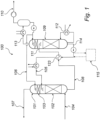
- FIG. 1 is a schematic representation of an amine based carbon dioxide (CO 2 ) capture system (100).
- the system comprises an absorption unit (101) arranged to allow contact between a gas stream to be purified and one or more wash liquids.
- the absorption unit represented in FIG. 1 comprises a CO 2 absorption section (102) and a water wash section (103). Flue gas, from which CO 2 is to be removed, is fed to the absorption unit (101) via line (104).
- the flue gas is contacted with a first wash liquid comprising an amine compound, e.g. by bubbling the flue gas through said first wash liquid or by spraying the first wash liquid into the flue gas.
- the first wash liquid is fed to the absorption unit (101) via line (105).
- CO 2 from the flue gas is absorbed in the first wash liquid. Flue gas depleted of CO 2 in the CO 2 absorption section then enters the water wash section (103) of the absorption unit.
- the water wash section (103) is arranged to allow contact between the flue gas depleted of CO 2 from the CO 2 absorption section (102) and a second wash liquid, which is generally water.
- the second wash liquid is fed to the absorption unit via line (106).
- contaminants remaining in the flue gas when it leaves the CO 2 absorption section are absorbed in the second wash liquid. Flue gas depleted of CO 2 and contaminants leaves the absorption unit via line (107).
- the used first and second wash liquid containing absorbed CO 2 and contaminants leave the absorption unit via line (108).
- the used first and second wash liquid may be recycled via a regenerator unit (109), wherein contaminants and CO 2 are separated from the wash water.
- the separated CO 2 leaves the system via line (110).
- the used first and second wash liquid to be regenerated enters the regenerator (109) via line (111).
- the used wash liquids are heated, generally using steam, in a reboiler (112). The heating causes desorption of absorbed CO 2 from the wash liquids.
- the desorbed CO 2 then exits the regenerator via line (113) together with some water vapor also formed during heating.
- Regenerated wash liquid, containing a reduced concentration of CO 2 leaves the regenerator (109) via line (114).
- the regenerated wash liquid is also referred to herein as "CO 2 lean amine absorbent" or simply "lean amine absorbent".
- the lean amine absorbent also contains heat stable salts (HSS) formed as degradation products in the regenerator as a result of the exposure to high temperature and/or the presence of O 2 (absorbed by the absorbent in the absorption unit).
- HSS heat stable salts
- the lean amine absorbent leaving the regenerator may be directed to a lean absorbent/rich absorbent heat exchanger (123) where it is used for pre-heating rich amine absorbent from line (108) directed towards the regenerator (109).
- the amine based carbon dioxide (CO 2 ) capture system (100) further comprises an amine absorbent reclaimer circuit (115) operative for at least partial removal of HSS from the circulating amine absorbent, so as to prevent accumulation of HSS and the problems associated therewith.
- the amine absorbent reclaimer circuit (115) is generally configured to withdraw a slipstream of the main amine absorbent flow.
- the amine absorbent reclaimer circuit (115) is configured to withdraw the slipstream of lean amine absorbent from a point in the process where the amine absorbent has a low CO 2 loading, i.e. lean amine absorbent.
- the slipstream of amine absorbent is withdrawn from the regenerator (109) or from the liquid conduit (114) between the regenerator (109) and a lean absorbent/rich absorbent heat exchanger (123).
- the lean amine absorbent from the regenerator generally has a temperature of 100 °C or higher, such as 120 °C or higher. This allows the thermal energy provided to the lean amine absorbent in the regenerator to be utilized in the stripping and/or flashing step.
- the slipstream of lean amine absorbent containing HSS may also be withdrawn from the lean absorbent/rich absorbent heat exchanger (123) or from the liquid conduit (105) between the lean absorbent/rich absorbent heat exchanger (123) and the CO 2 absorber (101) performing the scrubbing step.
- the slipstream may generally comprise in the range of 0.001-50 % by volume of the main amine absorbent flow, such as in the range of 0.01-10 % by volume of the main amine absorbent flow.
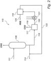
- FIG. 2 represents an amine based carbon dioxide (CO 2 ) capture system according to the invention, comprising an amine absorbent reclaimer circuit (115).
- the amine absorbent reclaimer circuit (115) is connected to the regenerator side of an amine based carbon dioxide (CO 2 ) capture system, e.g. as described above with reference to FIG. 1 .
- the amine absorbent reclaimer circuit (115) comprises an amine reclaimer (116) for separating heat stable salts from the amine absorbent.
- the amine reclaimer (116) is an electrodialysis (ED) unit.
- the ED unit is used to transport salt ions, e.g. HSS, from the amine absorbent through ion-exchange membranes to another solution under the influence of an applied electric potential difference.
- salt ions e.g. HSS
- the cell consists of a feed (diluate) compartment and a concentrate (e.g. brine) compartment formed by an anion exchange membrane and a cation exchange membrane placed between two electrodes.
- Multiple electrodialysis cells may be arranged into a configuration called an electrodialysis stack, with alternating anion and cation exchange membranes forming the multiple electrodialysis cells.
- the ED process results in a reduction of HSS in the amine absorbent as HSS ions are concentrated in the concentrate solution.
- the amine reclaimer (116) is an ion exchange unit comprising an ion exchange resin suitable for the removal of HSS ions from the amine absorbent.
- the amine absorbent reclaimer circuit (115) further comprises a residual CO 2 removal unit (117) arranged upstream of the amine reclaimer (116) with reference to the lean amine absorbent stream.
- the residual CO 2 removal unit (117) is a flash drum. Flash (or partial) evaporation is the partial vaporization that occurs when a saturated liquid stream undergoes a reduction in pressure by passing through a throttling valve or other throttling device. If the throttling valve or device is located at the entry into a pressure vessel so that the flash evaporation occurs within the vessel, then the vessel is often referred to as a flash drum.
- the flash drum comprises a pressure vessel having a feed inlet, a gas outlet and a liquid outlet.
- the feed inlet is equipped with a throttling device configured to decrease the pressure of the feed stream before it enters the pressure vessel.
- the lean amine absorbent enters the flash drum via a feed line (118).
- the temperature and pressure of the lean amine absorbent is determined by the temperature and pressure of the lean amine absorbent in, or leaving, the regeneration unit (109).
- the pressure of the lean amine absorbent may optionally be decreased by means of a throttling valve or device arranged in the feed inlet of the flash drum. In the flash drum, the pressure is then reduced, such that more volatile components, e.g. residual CO 2 , at least partially evaporate, while less volatile components, e.g. amine absorbent and water, remain in liquid phase.
- the pressure inside of the flash drum may preferably be low, such as in the range of 0-2 bar gauge. Evaporated components, e.g. residual CO 2 , leave the flash drum through a gas outlet via line (119), while liquid components, e.g. amine absorbent and water, leave the flash drum through a liquid outlet via line (120).
- the residual CO 2 removal unit (117) may further comprise a stripper.
- the stripper may, for example, comprise a generally cylindrical steel vessel configured to operate within a pre-determined pressure range.
- the stripper is preferably equipped with one or more suitable mass transfer devices, such as valve trays, sieve trays, structured packing, random packing or other suitable packing materials, or a combination thereof.
- a heating system/device may be provided in the stripper for heating the amine absorbent.
- the stripper is preferably configured to provide sufficient heat to the amine absorbent so that low boiling point components, for example CO 2 , are transferred to a gas phase, while high boiling point components, for example water and amine, are collected in a liquid phase at the bottom of the stripper.
- the amine absorbent may be heated up appropriately via, for example, a reboiler.
- the reboiler may be heated using, for example, electrically generated heat or steam.
- the stripper is configured to discharge the gas phase, containing CO 2 , via a gas exit, and the liquid phase, containing water and amine, via a liquid exit.
- the residual CO 2 removal unit (117) comprises a stripper and a flash drum arranged in series, such that a first portion of residual CO 2 may be removed in the stripper, and a second portion of residual CO 2 may be removed in the flash drum.
- the stripper and flash drum may be as described above.
- the lean amine absorbent first enters the stripper, where it is heated to a temperature sufficient to transfer low boiling point components, for example CO 2 , to a gas phase, while high boiling point components, for example water and amine, are collected in a liquid phase at the bottom of the stripper.
- the liquid phase is then forwarded to the flash drum, where the pressure is reduced so that more volatile components, e.g.
- residual CO 2 at least partially evaporate, while less volatile components, e.g. amine absorbent and water, remain in liquid phase.
- the lean amine absorbent from which residual CO 2 has been at least partially removed, is forwarded via line (120) to the amine reclaimer (116), wherein heat stable salts are at least partially separated from the amine absorbent to produce a lean amine absorbent depleted in HSS.
- the amine absorbent reclaimer circuit (115) further comprises a cooler (121) arranged between the residual CO 2 removal unit (117) and amine reclaimer, and configured to adjust the temperature of the lean amine absorbent from the residual CO 2 removal unit before it enters the amine reclaimer (116).
- a cooler (121) arranged between the residual CO 2 removal unit (117) and amine reclaimer, and configured to adjust the temperature of the lean amine absorbent from the residual CO 2 removal unit before it enters the amine reclaimer (116).
- an amine absorbent reclaimer circuit (115) comprising a cooler (121), may optionally further comprise an indirect heat exchanger (not shown) arranged between the residual CO 2 removal unit (117) and the cooler (121) and configured to cool the lean amine absorbent from the residual CO 2 removal unit (117) using the lean amine absorbent depleted in HSS leaving the amine reclaimer (116).
- the indirect heat exchanger may for example be a conventional plate or shell and tube type heat exchanger.
- the lean amine absorbent depleted in HSS leaves the amine reclaimer (116) and is forwarded via return line (122) back to the CO 2 capture system (100).
- the lean amine absorbent depleted in HSS may, for example be reintroduced into the regenerator (109), absorber (101), or into a suitable liquid conduit connecting the regenerator (109) and absorber (101).
- the position for reintroduction of the lean amine absorbent from the amine reclaimer circuit may be selected depending on the specific temperature and pressure of the absorbent.
- One suitable position for reintroduction would be into line (114), either upstream or downstream of a lean absorbent/rich absorbent heat exchanger (123).
- the separated heat stable salts leave the amine reclaimer via line (124).
- This example shows that a significant reduction of amine losses can be achieved by reduction of the CO 2 loading of the lean amine absorbent, e.g. by stripping or flashing, prior to feeding it to a reclaimer unit, such as an electrodialysis unit.
Landscapes
- Chemical & Material Sciences (AREA)
- Engineering & Computer Science (AREA)
- Chemical Kinetics & Catalysis (AREA)
- Organic Chemistry (AREA)
- General Chemical & Material Sciences (AREA)
- Oil, Petroleum & Natural Gas (AREA)
- Analytical Chemistry (AREA)
- Water Supply & Treatment (AREA)
- Health & Medical Sciences (AREA)
- Urology & Nephrology (AREA)
- Gas Separation By Absorption (AREA)
- Treating Waste Gases (AREA)
- Carbon And Carbon Compounds (AREA)
- Separation Using Semi-Permeable Membranes (AREA)
- Water Treatment By Electricity Or Magnetism (AREA)
Claims (11)
- Verfahren zum Entfernen von wärmestabilen Aminsalzen aus einem regenerierten Aminabsorptionsmittel, das eine reduzierte Konzentration von Kohlendioxid (CO2) aufweist, das in einem CO2-Einfangprozess durch ein Waschen eines Rauchgasstroms ausgebildet ist, der CO2 aufweist, wobei ein CO2-reiches Aminabsorptionsmittel durch ein Entfernen des CO2 aus dem Rauchgasstrom in einem CO2-Absorber (101) ausgebildet wird, und das regenerierte Aminabsorptionsmittel aus dem CO2-reichen Aminabsorptionsmittel in einem Regenerator (109) durch ein Erhitzen ausgebildet wird, um eine Desorption von CO2-Gas aus dem CO2-reichen Aminabsorptionsmittel zu bewirken, das regenerierte Aminabsorptionsmittel umfassend mindestens eine Aminverbindung, Rest-CO2 und die wärmestabilen Aminsalze, wobei das Verfahren gekennzeichnet ist durch:Zurückziehen eines Nachstroms des regenerierten Aminabsorptionsmittels aus dem Regenerator (109) oder aus einer Flüssigkeitsleitung zwischen dem Regenerator (109) und einem mager absorptionsfähigen/reich absorptionsfähigen Wärmetauscher (123);Aussetzen des Nachstroms einer Rest-CO2-Entfernung, umfassend ein Flashen des Nachstroms in einer Rest-CO2-Einheit (117), um Rest-CO2 zu entfernen, um ein CO2-mageres Aminabsorptionsmittel auszubilden; dannAussetzen des CO2-mageren Aminabsorptionsmittels einer Trennung in einem Aminverbesserungsmittel (116), um wärmestabile Aminsalze aus dem CO2-mageren Aminabsorptionsmittel zu entfernen, um ein verbessertes Aminabsorptionsmittel auszubilden, wobei die Trennung in dem Verbesserungsmittel das Aussetzen des CO2-mageren Aminabsorptionsmittels einer Elektrodialyse und einem lonenaustausch einschließt; undZurückführen des verbesserten Aminabsorptionsmittels, das eine verringerte Konzentration von wärmestabilen Aminsalzen aufweist, zu dem CO2-Einfangprozess.
- Verfahren nach Anspruch 1, wobei der Schritt des Aussetzens des Nachstroms der Rest-CO2-Entfernung ferner ein Strippen des Nachstroms in der Rest-CO2-Einheit (117) einschließt, um Rest-CO2 zu entfernen.
- Verfahren nach Anspruch 1, wobei das Flashen unter Beinahe-Vakuumbedingungen durchgeführt wird.
- Verfahren nach Anspruch 1, wobei der CO2-Einfangprozess umfasst:
Regenerieren des CO2-reichen Aminabsorptionsmittel durch Erhitzen des CO2-reichen Aminabsorptionsmittels, um CO2 aus dem CO2-reichen Aminabsorptionsmittel zu trennen, wodurch das regenerierte Aminabsorptionsmittel erzeugt wird, das eine verringerte Konzentration von CO2 aufweist, und das regenerierte Aminabsorptionsmittel wiederverwendet wird, um das Rauchgas zu waschen. - Verfahren nach Anspruch 4, wobei der Nachstrom des regenerierten Aminabsorptionsmittels eine Temperatur von mindestens 100 °C aufweist.
- Verfahren nach Anspruch 1, ferner umfassendein Abkühlen des CO2-mageren Aminabsorptionsmittels vor dem Aussetzen des CO2-mageren Aminabsorptionsmittels der Trennung.
- Verfahren nach Anspruch 6, ferner umfassenddas Aussetzen des CO2-mageren Aminabsorptionsmittels einem indirekten Wärmeaustausch mit dem verbesserten Aminabsorptionsmittel.
- Kohlendioxid(CO2)-Einfangsystem (100) unter Verwendung eines Aminabsorptionsmittels für die Absorption von CO2 aus einem Rauchgasstrom, wobei das CO2-Einfangsystem eine CO2-Absorptionseinheit (101) zum Entfernen von CO2 aus dem Rauchgasstrom unter Verwendung des Aminabsorptionsstroms aufweist, um ein CO2-reiches Aminabsorptionsmittel auszubilden, wobei die Absorptionseinheit (101) mit einer Regeneratoreinheit (109) in Verbindung steht, zum Entfernen von CO 2 aus dem CO2-reichen Aminabsorptionsmittel durch Erhitzen, um einen regenerierten Aminabsorptionsstrom auszubilden, wobei das CO2-Einfangsystem gekennzeichnet ist durch:
ein Subsystem (115) für die Entfernung von wärmestabilen Aminsalzen aus dem regenerierten Aminabsorptionsmittel, das Subsystem (115) umfassend:eine Rest-CO2-Entfernungseinheit (117) in Flüssigkeitsverbindung mit einem Nachstrom und konfiguriert, um diesen von dem regenerierten Aminabsorptionsmittel aus der Regeneratoreinheit (109) des CO,2-Einfangsystems (100) oder aus einer Flüssigkeitsleitung zwischen dem Regenerator (109) und dem mager absorptionsfähigen/reich absorptionsfähigen Wärmetauscher (123) aufzunehmen und betriebsfähig ist zum Trennen von Rest-CO2 aus dem Nachstrom, um ein CO2-mageres Aminabsorptionsmittel auszubilden, das restliche CO2-Entfernungseinheit (117) umfassend eine Entspannungstrommel; undein Aminverbesserungsmittel (116) in flüssiger Verbindung mit dem CO2-mageren Aminabsorptionsstrom und konfiguriert, um diesen zu empfangen, der eine weitere reduzierte Konzentration von CO2 von der Rest-CO2-Entfernungseinheit (117) aufweist und betriebsfähig ist zum Trennen von wärmestabilen Aminsalzen aus dem CO2-mageren Aminabsorptionsmittel, um ein verbessertes Aminabsorptionsmittel auszubilden, die Aminverbesserungsmitteleinheit (116) ferner umfassend eine Elektrodialyseeinheit und eine lonenaustauscheinheit. - CO2-Einfangsystem (100) nach Anspruch 8, wobeidie Rest-CO2-Entfernungseinheit (117) einen Stripper und die in Reihe angeordnete Entspannungstrommel umfasst.
- CO2-Einfangsystem (100) nach Anspruch 8, ferner umfassend einen Aminabsorptionskühler (121), der zwischen der Rest-CO 2-Entfernungseinheit (117) und der Verbesserungsmitteleinheit (116) angeordnet ist und betriebsfähig ist zum Kühlen des CO2-mageren Aminabsorptionsmittels aus der Rest-CO2-Entferungseinheit (117), bevor das CO2-magere Aminabsorptionsmittel in das Verbesserungsmittel (116) eintritt.
- CO 2-Einfangsystem (100) nach Anspruch 10, ferner umfassendeinen indirekten Wärmetauscher, der betriebsfähig ist zum Aussetzen des CO2-mageren Absorptionsmittels aus der Rest-CO2-Entfernungseinheit (117) einem indirekten Wärmeaustausch mit dem verbesserten Aminabsorptionsmittel, das von der Verbesserungsmitteleinheit (116) kommt.
Applications Claiming Priority (3)
| Application Number | Priority Date | Filing Date | Title |
|---|---|---|---|
| US201161454079P | 2011-03-18 | 2011-03-18 | |
| US13/248,344 US20120235087A1 (en) | 2011-03-18 | 2011-09-29 | Method for the removal of heat stable amine salts from an amine absorbent |
| PCT/US2012/028889 WO2012129001A1 (en) | 2011-03-18 | 2012-03-13 | A method for the removal of heat stable amine salts from an amine absorbent |
Publications (3)
| Publication Number | Publication Date |
|---|---|
| EP2686087A1 EP2686087A1 (de) | 2014-01-22 |
| EP2686087B1 EP2686087B1 (de) | 2019-12-18 |
| EP2686087B2 true EP2686087B2 (de) | 2023-06-07 |
Family
ID=46827747
Family Applications (1)
| Application Number | Title | Priority Date | Filing Date |
|---|---|---|---|
| EP12712467.5A Active EP2686087B2 (de) | 2011-03-18 | 2012-03-13 | Verfahren und vorrichtung zur entfernung von hitzestabilen aminsalzen aus einem aminabsorbens |
Country Status (8)
| Country | Link |
|---|---|
| US (2) | US20120235087A1 (de) |
| EP (1) | EP2686087B2 (de) |
| JP (1) | JP2014512944A (de) |
| CN (1) | CN103476481B (de) |
| AU (1) | AU2012231370B2 (de) |
| CA (1) | CA2830343A1 (de) |
| TW (1) | TW201244810A (de) |
| WO (1) | WO2012129001A1 (de) |
Families Citing this family (22)
| Publication number | Priority date | Publication date | Assignee | Title |
|---|---|---|---|---|
| EP2481466A1 (de) * | 2011-01-31 | 2012-08-01 | Siemens Aktiengesellschaft | Vorrichtung und Verfahren zum Aufreinigen eines mit Nitrosamin verunreinigten Produktes einer Prozessanlage |
| US20120235087A1 (en) | 2011-03-18 | 2012-09-20 | Dow Global Technologies Llc | Method for the removal of heat stable amine salts from an amine absorbent |
| US9623366B2 (en) * | 2013-03-04 | 2017-04-18 | Mitsubishi Heavy Industries, Ltd. | CO2 recovery system and CO2 recovery method |
| US9334455B2 (en) | 2013-06-28 | 2016-05-10 | Uop Llc | Methods and apparatuses for enhanced absorption of acid gas components from sour feed gas |
| JP2015134334A (ja) * | 2014-01-17 | 2015-07-27 | 三菱重工業株式会社 | リクレーミング装置及び方法、co2又はh2s又はその双方の回収装置 |
| US10005019B2 (en) * | 2014-02-21 | 2018-06-26 | Sharp Kabushiki Kaisha | Carbon dioxide concentration-controlling device and electronic apparatus |
| WO2015138940A1 (en) | 2014-03-13 | 2015-09-17 | Fluor Technologies Corporation | Removal of metals from co2 capture solvents |
| US10232304B2 (en) | 2014-08-20 | 2019-03-19 | Sharp Kabushiki Kaisha | Carbon dioxide concentration control system and carbon dioxide concentration control device |
| KR101839225B1 (ko) * | 2016-09-08 | 2018-03-15 | 주식회사 포스코 | 코크스 오븐 가스 정제 방법 및 정제 장치 |
| KR101839590B1 (ko) * | 2017-05-15 | 2018-03-16 | (주)시온텍 | 유체 순환형 산성가스 제거 장치 및 방법 |
| JP6882154B2 (ja) * | 2017-12-26 | 2021-06-02 | 株式会社東芝 | 二酸化炭素成分除去装置および二酸化炭素成分除去方法ならびに二酸化炭素ガス除去装置 |
| CN108726477B (zh) * | 2018-06-15 | 2021-08-03 | 上海理工大学 | 一种热平衡紧凑固定床化学链制氢脱碳一体化装置及方法 |
| CN108970334B (zh) * | 2018-08-02 | 2020-10-27 | 中国科学技术大学 | 用于富碳胺液的再生系统及其用途 |
| CN112742176B (zh) * | 2019-10-30 | 2023-05-05 | 中国石油化工股份有限公司 | 一种净化脱除胺液中热稳定盐的方法及装置 |
| CN113041786B (zh) * | 2019-12-26 | 2022-06-14 | 国家能源投资集团有限责任公司 | 一种二氧化碳捕集胺液的净化方法及其应用 |
| US12186682B2 (en) | 2021-12-03 | 2025-01-07 | Saudi Arabian Oil Company | Restoring accumulated DGA with reclaimer sparge line |
| US12043810B2 (en) | 2021-12-07 | 2024-07-23 | Saudi Arabian Oil Company | Control scheme for amine contactor |
| CN114210206B (zh) * | 2021-12-15 | 2022-09-20 | 浙江大学 | 一种回收有机胺co2贫液废液的两段电渗析系统和方法 |
| CN114247291B (zh) * | 2021-12-21 | 2023-08-11 | 浙江志澄环境资源科技有限公司 | 一种去除工业二氧化碳捕获系统中热稳盐的工作方法 |
| JP7661261B2 (ja) | 2022-03-10 | 2025-04-14 | 株式会社東芝 | 電気透析システムおよびco2回収システム |
| JP2025520235A (ja) * | 2022-06-23 | 2025-07-03 | エレクトロセップ インコーポレイテッド | 炭素捕捉及び他の酸性ガス回収のためのゼロ液体排出アミン再生方法 |
| CN116870663B (zh) * | 2023-08-04 | 2024-08-23 | 中国石油天然气集团有限公司 | 一种胺液净化再生系统及方法 |
Citations (11)
| Publication number | Priority date | Publication date | Assignee | Title |
|---|---|---|---|---|
| US5137702A (en) † | 1988-12-22 | 1992-08-11 | Mobil Oil Corporation | Regeneration of used alkanolamine solutions |
| US5292407A (en) † | 1992-12-18 | 1994-03-08 | Union Carbide Chemicals & Plastics Technology Corporation | Process for converting heat stable amine salts to heat regenerable amine salts |
| WO1998032520A1 (en) † | 1997-01-24 | 1998-07-30 | Mpr Services, Inc. | Process for treating gas with ultra-lean amine |
| US5788864A (en) † | 1995-02-24 | 1998-08-04 | Mpr Services | Amine heat stable salt removal from type II anion exchange resin |
| US5910611A (en) † | 1987-04-09 | 1999-06-08 | Union Carbide Chemicals & Plastics Technology Corporation | Aqueous alkanolamines using an electrodialysis cell with an ion exchange membrane |
| EP1601445A1 (de) † | 2003-03-10 | 2005-12-07 | Board Of Regents, The University Of Texas System | Regenerierung einer wässrigen lösung aus einem sauergasabsorptionsverfahren mittels mehrstufigem stripping und flashing |
| US20070286785A1 (en) † | 2006-06-09 | 2007-12-13 | Roy Wade Rhodes | Optimization of amine regeneration system start-up using flash tank pressurization |
| US20100062926A1 (en) † | 2006-11-24 | 2010-03-11 | Simon Woodhouse | Absorbent regeneration with flashed lean solution and heat integration |
| CA2736222A1 (en) † | 2008-10-14 | 2010-04-22 | Exxonmobil Upstream Research Company | Removal of acid gases from a gas stream |
| US20100108610A1 (en) † | 2008-11-06 | 2010-05-06 | Vijay Bhambhani Godhwani | Method for Treating a Diamine Absorbent Stream |
| EP2667958A1 (de) † | 2011-01-24 | 2013-12-04 | Electrosep Technologies Inc. | Verfahren zur entfernung wärmestabiler basissalze aus einer verunreinigten basischen lösung und seine anwendung in einem prozess zur säuregasrückgewinnung aus einem säuregasstrom |
Family Cites Families (17)
| Publication number | Priority date | Publication date | Assignee | Title |
|---|---|---|---|---|
| US2768945A (en) | 1953-03-09 | 1956-10-30 | Socony Mobil Oil Co Inc | Method of separating acidic gases from fluid mixtures |
| US3554690A (en) | 1969-01-15 | 1971-01-12 | Girdler Inc C & I | Apparatus and method for removing carbon dioxide from process gases |
| US4245569A (en) | 1979-03-26 | 1981-01-20 | Combustion Engineering, Inc. | Scrubber bypass system |
| US5338521A (en) | 1992-11-10 | 1994-08-16 | Air Products And Chemicals, Inc. | Process for reversibly absorbing acid gases from gaseous mixtures |
| US5601784A (en) | 1994-09-09 | 1997-02-11 | Electric Power Research Institute | On-line control and monitoring system for wet lime/limestone flue gas desulfurization process |
| US5912387A (en) | 1997-01-28 | 1999-06-15 | The Dow Chemical Company | Amine heat stable salt neutralization having reduced solids |
| US6187277B1 (en) | 1999-06-04 | 2001-02-13 | Leon Kirschner | Method for purifying gases |
| US6517700B2 (en) * | 2000-05-02 | 2003-02-11 | Carolyn H. Byszewski | Process for the removal of heat stable amine salts |
| US6497852B2 (en) * | 2000-12-22 | 2002-12-24 | Shrikar Chakravarti | Carbon dioxide recovery at high pressure |
| US7192468B2 (en) * | 2002-04-15 | 2007-03-20 | Fluor Technologies Corporation | Configurations and method for improved gas removal |
| US20070148068A1 (en) * | 2005-12-23 | 2007-06-28 | Burgers Kenneth L | Reclaiming amines in carbon dioxide recovery |
| US7601315B2 (en) * | 2006-12-28 | 2009-10-13 | Cansolv Technologies Inc. | Process for the recovery of carbon dioxide from a gas stream |
| US20100074828A1 (en) | 2008-01-28 | 2010-03-25 | Fluegen, Inc. | Method and Apparatus for the Removal of Carbon Dioxide from a Gas Stream |
| US8226893B2 (en) | 2008-06-24 | 2012-07-24 | Mclauchlan Robert A | Automated sulfur recovery loop |
| NO20092229L (no) * | 2009-06-09 | 2010-12-10 | Aker Clean Carbon As | Reclaimer for absorbent |
| JP5660303B2 (ja) * | 2010-11-18 | 2015-01-28 | 栗田エンジニアリング株式会社 | アミン液の再生方法 |
| US20120235087A1 (en) | 2011-03-18 | 2012-09-20 | Dow Global Technologies Llc | Method for the removal of heat stable amine salts from an amine absorbent |
-
2011
- 2011-09-29 US US13/248,344 patent/US20120235087A1/en not_active Abandoned
-
2012
- 2012-03-13 CN CN201280014045.3A patent/CN103476481B/zh active Active
- 2012-03-13 CA CA2830343A patent/CA2830343A1/en not_active Abandoned
- 2012-03-13 WO PCT/US2012/028889 patent/WO2012129001A1/en not_active Ceased
- 2012-03-13 JP JP2014501141A patent/JP2014512944A/ja active Pending
- 2012-03-13 AU AU2012231370A patent/AU2012231370B2/en not_active Ceased
- 2012-03-13 EP EP12712467.5A patent/EP2686087B2/de active Active
- 2012-03-16 TW TW101109235A patent/TW201244810A/zh unknown
-
2016
- 2016-08-31 US US15/253,243 patent/US10456749B2/en active Active
Patent Citations (11)
| Publication number | Priority date | Publication date | Assignee | Title |
|---|---|---|---|---|
| US5910611A (en) † | 1987-04-09 | 1999-06-08 | Union Carbide Chemicals & Plastics Technology Corporation | Aqueous alkanolamines using an electrodialysis cell with an ion exchange membrane |
| US5137702A (en) † | 1988-12-22 | 1992-08-11 | Mobil Oil Corporation | Regeneration of used alkanolamine solutions |
| US5292407A (en) † | 1992-12-18 | 1994-03-08 | Union Carbide Chemicals & Plastics Technology Corporation | Process for converting heat stable amine salts to heat regenerable amine salts |
| US5788864A (en) † | 1995-02-24 | 1998-08-04 | Mpr Services | Amine heat stable salt removal from type II anion exchange resin |
| WO1998032520A1 (en) † | 1997-01-24 | 1998-07-30 | Mpr Services, Inc. | Process for treating gas with ultra-lean amine |
| EP1601445A1 (de) † | 2003-03-10 | 2005-12-07 | Board Of Regents, The University Of Texas System | Regenerierung einer wässrigen lösung aus einem sauergasabsorptionsverfahren mittels mehrstufigem stripping und flashing |
| US20070286785A1 (en) † | 2006-06-09 | 2007-12-13 | Roy Wade Rhodes | Optimization of amine regeneration system start-up using flash tank pressurization |
| US20100062926A1 (en) † | 2006-11-24 | 2010-03-11 | Simon Woodhouse | Absorbent regeneration with flashed lean solution and heat integration |
| CA2736222A1 (en) † | 2008-10-14 | 2010-04-22 | Exxonmobil Upstream Research Company | Removal of acid gases from a gas stream |
| US20100108610A1 (en) † | 2008-11-06 | 2010-05-06 | Vijay Bhambhani Godhwani | Method for Treating a Diamine Absorbent Stream |
| EP2667958A1 (de) † | 2011-01-24 | 2013-12-04 | Electrosep Technologies Inc. | Verfahren zur entfernung wärmestabiler basissalze aus einer verunreinigten basischen lösung und seine anwendung in einem prozess zur säuregasrückgewinnung aus einem säuregasstrom |
Also Published As
| Publication number | Publication date |
|---|---|
| EP2686087A1 (de) | 2014-01-22 |
| WO2012129001A1 (en) | 2012-09-27 |
| EP2686087B1 (de) | 2019-12-18 |
| US20160367944A1 (en) | 2016-12-22 |
| AU2012231370B2 (en) | 2015-04-23 |
| CN103476481B (zh) | 2017-05-03 |
| CN103476481A (zh) | 2013-12-25 |
| US20120235087A1 (en) | 2012-09-20 |
| JP2014512944A (ja) | 2014-05-29 |
| TW201244810A (en) | 2012-11-16 |
| US10456749B2 (en) | 2019-10-29 |
| AU2012231370A1 (en) | 2013-09-26 |
| CA2830343A1 (en) | 2012-09-27 |
Similar Documents
| Publication | Publication Date | Title |
|---|---|---|
| EP2686087B2 (de) | Verfahren und vorrichtung zur entfernung von hitzestabilen aminsalzen aus einem aminabsorbens | |
| Wang et al. | Amine reclaiming technologies in post-combustion carbon dioxide capture | |
| US8357344B2 (en) | Gas deacidizing method using an absorbent solution with vaporization and/or purification of a fraction of the regenerated absorbent solution | |
| JP5658243B2 (ja) | Co2吸収剤の再生利用のための方法および再生利用器 | |
| JP5703106B2 (ja) | アミン回収システム及び二酸化炭素回収システム | |
| CN104160268B (zh) | 酸性气体去除装置 | |
| US20120219482A1 (en) | Systems and processes for removing volatile degradation products produced in gas purification | |
| CN104284881B (zh) | 回收单一或混合胺溶剂的系统和方法 | |
| KR20120023718A (ko) | 산성 가스의 분리에 사용되는 자기 농축 흡수제 | |
| US8833081B2 (en) | Low pressure steam pre-heaters for gas purification systems and processes of use | |
| EP2230000B1 (de) | Vorrichtung und Verfahren zur Abgasbehandlung mit Ammoniaklösung | |
| US10213728B2 (en) | Method for separating carbon dioxide from a gas flow, in particular from a flue gas flow, and separating device for separating carbon dioxide from a gas flow, in particular from a flue gas flow | |
| US8486358B2 (en) | Carbon dioxide capture method, with optimized acid wash section | |
| JP4831833B2 (ja) | Co2回収装置及びco2回収装置における廃棄物処理方法 | |
| FR2958180A1 (fr) | Procede de desacidification d'un gaz par une solution absorbante, avec section de lavage acide | |
| CA2834664C (en) | Method and apparatus for capturing sox in a flue gas processing system |
Legal Events
| Date | Code | Title | Description |
|---|---|---|---|
| TPAC | Observations filed by third parties |
Free format text: ORIGINAL CODE: EPIDOSNTIPA |
|
| PUAI | Public reference made under article 153(3) epc to a published international application that has entered the european phase |
Free format text: ORIGINAL CODE: 0009012 |
|
| 17P | Request for examination filed |
Effective date: 20130911 |
|
| AK | Designated contracting states |
Kind code of ref document: A1 Designated state(s): AL AT BE BG CH CY CZ DE DK EE ES FI FR GB GR HR HU IE IS IT LI LT LU LV MC MK MT NL NO PL PT RO RS SE SI SK SM TR |
|
| DAX | Request for extension of the european patent (deleted) | ||
| 17Q | First examination report despatched |
Effective date: 20160629 |
|
| RAP1 | Party data changed (applicant data changed or rights of an application transferred) |
Owner name: DOW GLOBAL TECHNOLOGIES LLC Owner name: GENERAL ELECTRIC TECHNOLOGY GMBH Owner name: VITSE, FREDERIC |
|
| RAP1 | Party data changed (applicant data changed or rights of an application transferred) |
Owner name: DOW GLOBAL TECHNOLOGIES LLC Owner name: GENERAL ELECTRIC TECHNOLOGY GMBH |
|
| TPAC | Observations filed by third parties |
Free format text: ORIGINAL CODE: EPIDOSNTIPA |
|
| STAA | Information on the status of an ep patent application or granted ep patent |
Free format text: STATUS: EXAMINATION IS IN PROGRESS |
|
| GRAP | Despatch of communication of intention to grant a patent |
Free format text: ORIGINAL CODE: EPIDOSNIGR1 |
|
| STAA | Information on the status of an ep patent application or granted ep patent |
Free format text: STATUS: GRANT OF PATENT IS INTENDED |
|
| INTG | Intention to grant announced |
Effective date: 20190628 |
|
| GRAS | Grant fee paid |
Free format text: ORIGINAL CODE: EPIDOSNIGR3 |
|
| GRAA | (expected) grant |
Free format text: ORIGINAL CODE: 0009210 |
|
| STAA | Information on the status of an ep patent application or granted ep patent |
Free format text: STATUS: THE PATENT HAS BEEN GRANTED |
|
| AK | Designated contracting states |
Kind code of ref document: B1 Designated state(s): AL AT BE BG CH CY CZ DE DK EE ES FI FR GB GR HR HU IE IS IT LI LT LU LV MC MK MT NL NO PL PT RO RS SE SI SK SM TR |
|
| REG | Reference to a national code |
Ref country code: GB Ref legal event code: FG4D |
|
| REG | Reference to a national code |
Ref country code: CH Ref legal event code: EP |
|
| REG | Reference to a national code |
Ref country code: IE Ref legal event code: FG4D |
|
| REG | Reference to a national code |
Ref country code: DE Ref legal event code: R096 Ref document number: 602012066541 Country of ref document: DE |
|
| REG | Reference to a national code |
Ref country code: AT Ref legal event code: REF Ref document number: 1213966 Country of ref document: AT Kind code of ref document: T Effective date: 20200115 |
|
| REG | Reference to a national code |
Ref country code: NL Ref legal event code: FP |
|
| REG | Reference to a national code |
Ref country code: NO Ref legal event code: T2 Effective date: 20191218 |
|
| PG25 | Lapsed in a contracting state [announced via postgrant information from national office to epo] |
Ref country code: FI Free format text: LAPSE BECAUSE OF FAILURE TO SUBMIT A TRANSLATION OF THE DESCRIPTION OR TO PAY THE FEE WITHIN THE PRESCRIBED TIME-LIMIT Effective date: 20191218 Ref country code: BG Free format text: LAPSE BECAUSE OF FAILURE TO SUBMIT A TRANSLATION OF THE DESCRIPTION OR TO PAY THE FEE WITHIN THE PRESCRIBED TIME-LIMIT Effective date: 20200318 Ref country code: LT Free format text: LAPSE BECAUSE OF FAILURE TO SUBMIT A TRANSLATION OF THE DESCRIPTION OR TO PAY THE FEE WITHIN THE PRESCRIBED TIME-LIMIT Effective date: 20191218 Ref country code: LV Free format text: LAPSE BECAUSE OF FAILURE TO SUBMIT A TRANSLATION OF THE DESCRIPTION OR TO PAY THE FEE WITHIN THE PRESCRIBED TIME-LIMIT Effective date: 20191218 Ref country code: SE Free format text: LAPSE BECAUSE OF FAILURE TO SUBMIT A TRANSLATION OF THE DESCRIPTION OR TO PAY THE FEE WITHIN THE PRESCRIBED TIME-LIMIT Effective date: 20191218 Ref country code: GR Free format text: LAPSE BECAUSE OF FAILURE TO SUBMIT A TRANSLATION OF THE DESCRIPTION OR TO PAY THE FEE WITHIN THE PRESCRIBED TIME-LIMIT Effective date: 20200319 |
|
| REG | Reference to a national code |
Ref country code: LT Ref legal event code: MG4D |
|
| PG25 | Lapsed in a contracting state [announced via postgrant information from national office to epo] |
Ref country code: HR Free format text: LAPSE BECAUSE OF FAILURE TO SUBMIT A TRANSLATION OF THE DESCRIPTION OR TO PAY THE FEE WITHIN THE PRESCRIBED TIME-LIMIT Effective date: 20191218 Ref country code: RS Free format text: LAPSE BECAUSE OF FAILURE TO SUBMIT A TRANSLATION OF THE DESCRIPTION OR TO PAY THE FEE WITHIN THE PRESCRIBED TIME-LIMIT Effective date: 20191218 |
|
| PG25 | Lapsed in a contracting state [announced via postgrant information from national office to epo] |
Ref country code: AL Free format text: LAPSE BECAUSE OF FAILURE TO SUBMIT A TRANSLATION OF THE DESCRIPTION OR TO PAY THE FEE WITHIN THE PRESCRIBED TIME-LIMIT Effective date: 20191218 |
|
| PG25 | Lapsed in a contracting state [announced via postgrant information from national office to epo] |
Ref country code: EE Free format text: LAPSE BECAUSE OF FAILURE TO SUBMIT A TRANSLATION OF THE DESCRIPTION OR TO PAY THE FEE WITHIN THE PRESCRIBED TIME-LIMIT Effective date: 20191218 Ref country code: RO Free format text: LAPSE BECAUSE OF FAILURE TO SUBMIT A TRANSLATION OF THE DESCRIPTION OR TO PAY THE FEE WITHIN THE PRESCRIBED TIME-LIMIT Effective date: 20191218 Ref country code: CZ Free format text: LAPSE BECAUSE OF FAILURE TO SUBMIT A TRANSLATION OF THE DESCRIPTION OR TO PAY THE FEE WITHIN THE PRESCRIBED TIME-LIMIT Effective date: 20191218 Ref country code: PT Free format text: LAPSE BECAUSE OF FAILURE TO SUBMIT A TRANSLATION OF THE DESCRIPTION OR TO PAY THE FEE WITHIN THE PRESCRIBED TIME-LIMIT Effective date: 20200513 |
|
| PG25 | Lapsed in a contracting state [announced via postgrant information from national office to epo] |
Ref country code: IS Free format text: LAPSE BECAUSE OF FAILURE TO SUBMIT A TRANSLATION OF THE DESCRIPTION OR TO PAY THE FEE WITHIN THE PRESCRIBED TIME-LIMIT Effective date: 20200418 Ref country code: SK Free format text: LAPSE BECAUSE OF FAILURE TO SUBMIT A TRANSLATION OF THE DESCRIPTION OR TO PAY THE FEE WITHIN THE PRESCRIBED TIME-LIMIT Effective date: 20191218 Ref country code: SM Free format text: LAPSE BECAUSE OF FAILURE TO SUBMIT A TRANSLATION OF THE DESCRIPTION OR TO PAY THE FEE WITHIN THE PRESCRIBED TIME-LIMIT Effective date: 20191218 |
|
| REG | Reference to a national code |
Ref country code: DE Ref legal event code: R026 Ref document number: 602012066541 Country of ref document: DE |
|
| PLBI | Opposition filed |
Free format text: ORIGINAL CODE: 0009260 |
|
| PLAX | Notice of opposition and request to file observation + time limit sent |
Free format text: ORIGINAL CODE: EPIDOSNOBS2 |
|
| REG | Reference to a national code |
Ref country code: AT Ref legal event code: MK05 Ref document number: 1213966 Country of ref document: AT Kind code of ref document: T Effective date: 20191218 |
|
| 26 | Opposition filed |
Opponent name: ELECTROSEP TECHNOLOGIES INC. Effective date: 20200917 |
|
| PG25 | Lapsed in a contracting state [announced via postgrant information from national office to epo] |
Ref country code: ES Free format text: LAPSE BECAUSE OF FAILURE TO SUBMIT A TRANSLATION OF THE DESCRIPTION OR TO PAY THE FEE WITHIN THE PRESCRIBED TIME-LIMIT Effective date: 20191218 Ref country code: DK Free format text: LAPSE BECAUSE OF FAILURE TO SUBMIT A TRANSLATION OF THE DESCRIPTION OR TO PAY THE FEE WITHIN THE PRESCRIBED TIME-LIMIT Effective date: 20191218 Ref country code: MC Free format text: LAPSE BECAUSE OF FAILURE TO SUBMIT A TRANSLATION OF THE DESCRIPTION OR TO PAY THE FEE WITHIN THE PRESCRIBED TIME-LIMIT Effective date: 20191218 |
|
| REG | Reference to a national code |
Ref country code: CH Ref legal event code: PL |
|
| PG25 | Lapsed in a contracting state [announced via postgrant information from national office to epo] |
Ref country code: SI Free format text: LAPSE BECAUSE OF FAILURE TO SUBMIT A TRANSLATION OF THE DESCRIPTION OR TO PAY THE FEE WITHIN THE PRESCRIBED TIME-LIMIT Effective date: 20191218 Ref country code: AT Free format text: LAPSE BECAUSE OF FAILURE TO SUBMIT A TRANSLATION OF THE DESCRIPTION OR TO PAY THE FEE WITHIN THE PRESCRIBED TIME-LIMIT Effective date: 20191218 |
|
| REG | Reference to a national code |
Ref country code: BE Ref legal event code: MM Effective date: 20200331 |
|
| PG25 | Lapsed in a contracting state [announced via postgrant information from national office to epo] |
Ref country code: LU Free format text: LAPSE BECAUSE OF NON-PAYMENT OF DUE FEES Effective date: 20200313 |
|
| PLAF | Information modified related to communication of a notice of opposition and request to file observations + time limit |
Free format text: ORIGINAL CODE: EPIDOSCOBS2 |
|
| PG25 | Lapsed in a contracting state [announced via postgrant information from national office to epo] |
Ref country code: IE Free format text: LAPSE BECAUSE OF NON-PAYMENT OF DUE FEES Effective date: 20200313 Ref country code: LI Free format text: LAPSE BECAUSE OF NON-PAYMENT OF DUE FEES Effective date: 20200331 Ref country code: FR Free format text: LAPSE BECAUSE OF NON-PAYMENT OF DUE FEES Effective date: 20200331 Ref country code: CH Free format text: LAPSE BECAUSE OF NON-PAYMENT OF DUE FEES Effective date: 20200331 Ref country code: IT Free format text: LAPSE BECAUSE OF FAILURE TO SUBMIT A TRANSLATION OF THE DESCRIPTION OR TO PAY THE FEE WITHIN THE PRESCRIBED TIME-LIMIT Effective date: 20191218 |
|
| PG25 | Lapsed in a contracting state [announced via postgrant information from national office to epo] |
Ref country code: BE Free format text: LAPSE BECAUSE OF NON-PAYMENT OF DUE FEES Effective date: 20200331 Ref country code: PL Free format text: LAPSE BECAUSE OF FAILURE TO SUBMIT A TRANSLATION OF THE DESCRIPTION OR TO PAY THE FEE WITHIN THE PRESCRIBED TIME-LIMIT Effective date: 20191218 |
|
| PLBB | Reply of patent proprietor to notice(s) of opposition received |
Free format text: ORIGINAL CODE: EPIDOSNOBS3 |
|
| REG | Reference to a national code |
Ref country code: DE Ref legal event code: R082 Ref document number: 602012066541 Country of ref document: DE |
|
| RAP4 | Party data changed (patent owner data changed or rights of a patent transferred) |
Owner name: GENERAL ELECTRIC TECHNOLOGY GMBH Owner name: DOW GLOBAL TECHNOLOGIES LLC |
|
| PG25 | Lapsed in a contracting state [announced via postgrant information from national office to epo] |
Ref country code: TR Free format text: LAPSE BECAUSE OF FAILURE TO SUBMIT A TRANSLATION OF THE DESCRIPTION OR TO PAY THE FEE WITHIN THE PRESCRIBED TIME-LIMIT Effective date: 20191218 Ref country code: MT Free format text: LAPSE BECAUSE OF FAILURE TO SUBMIT A TRANSLATION OF THE DESCRIPTION OR TO PAY THE FEE WITHIN THE PRESCRIBED TIME-LIMIT Effective date: 20191218 Ref country code: CY Free format text: LAPSE BECAUSE OF FAILURE TO SUBMIT A TRANSLATION OF THE DESCRIPTION OR TO PAY THE FEE WITHIN THE PRESCRIBED TIME-LIMIT Effective date: 20191218 |
|
| PG25 | Lapsed in a contracting state [announced via postgrant information from national office to epo] |
Ref country code: MK Free format text: LAPSE BECAUSE OF FAILURE TO SUBMIT A TRANSLATION OF THE DESCRIPTION OR TO PAY THE FEE WITHIN THE PRESCRIBED TIME-LIMIT Effective date: 20191218 |
|
| PLAB | Opposition data, opponent's data or that of the opponent's representative modified |
Free format text: ORIGINAL CODE: 0009299OPPO |
|
| R26 | Opposition filed (corrected) |
Opponent name: ELECTROSEP TECHNOLOGIES INC. Effective date: 20200917 |
|
| REG | Reference to a national code |
Ref country code: CH Ref legal event code: PK Free format text: BERICHTIGUNGEN |
|
| RIC2 | Information provided on ipc code assigned after grant |
Ipc: C07C 209/84 20060101ALI20221013BHEP Ipc: B01D 61/42 20060101ALI20221013BHEP Ipc: B01D 53/14 20060101ALI20221013BHEP Ipc: B01J 47/00 20170101AFI20221013BHEP |
|
| PUAH | Patent maintained in amended form |
Free format text: ORIGINAL CODE: 0009272 |
|
| STAA | Information on the status of an ep patent application or granted ep patent |
Free format text: STATUS: PATENT MAINTAINED AS AMENDED |
|
| 27A | Patent maintained in amended form |
Effective date: 20230607 |
|
| AK | Designated contracting states |
Kind code of ref document: B2 Designated state(s): AL AT BE BG CH CY CZ DE DK EE ES FI FR GB GR HR HU IE IS IT LI LT LU LV MC MK MT NL NO PL PT RO RS SE SI SK SM TR |
|
| REG | Reference to a national code |
Ref country code: DE Ref legal event code: R102 Ref document number: 602012066541 Country of ref document: DE |
|
| P01 | Opt-out of the competence of the unified patent court (upc) registered |
Effective date: 20230522 |
|
| REG | Reference to a national code |
Ref country code: NL Ref legal event code: FP |
|
| REG | Reference to a national code |
Ref country code: NO Ref legal event code: T2 Effective date: 20191218 |
|
| PGFP | Annual fee paid to national office [announced via postgrant information from national office to epo] |
Ref country code: NL Payment date: 20260219 Year of fee payment: 15 |
|
| PGFP | Annual fee paid to national office [announced via postgrant information from national office to epo] |
Ref country code: GB Payment date: 20260219 Year of fee payment: 15 |
|
| PGFP | Annual fee paid to national office [announced via postgrant information from national office to epo] |
Ref country code: NO Payment date: 20260223 Year of fee payment: 15 Ref country code: DE Payment date: 20260219 Year of fee payment: 15 |