EP2686151B1 - Blasform - Google Patents
Blasform Download PDFInfo
- Publication number
- EP2686151B1 EP2686151B1 EP12714246.1A EP12714246A EP2686151B1 EP 2686151 B1 EP2686151 B1 EP 2686151B1 EP 12714246 A EP12714246 A EP 12714246A EP 2686151 B1 EP2686151 B1 EP 2686151B1
- Authority
- EP
- European Patent Office
- Prior art keywords
- slider
- blow mould
- connection
- mould according
- collector
- Prior art date
- Legal status (The legal status is an assumption and is not a legal conclusion. Google has not performed a legal analysis and makes no representation as to the accuracy of the status listed.)
- Active
Links
Images




Classifications
-
- B—PERFORMING OPERATIONS; TRANSPORTING
- B29—WORKING OF PLASTICS; WORKING OF SUBSTANCES IN A PLASTIC STATE IN GENERAL
- B29C—SHAPING OR JOINING OF PLASTICS; SHAPING OF MATERIAL IN A PLASTIC STATE, NOT OTHERWISE PROVIDED FOR; AFTER-TREATMENT OF THE SHAPED PRODUCTS, e.g. REPAIRING
- B29C49/00—Blow-moulding, i.e. blowing a preform or parison to a desired shape within a mould; Apparatus therefor
- B29C49/28—Blow-moulding apparatus
- B29C49/30—Blow-moulding apparatus having movable moulds or mould parts
-
- B—PERFORMING OPERATIONS; TRANSPORTING
- B29—WORKING OF PLASTICS; WORKING OF SUBSTANCES IN A PLASTIC STATE IN GENERAL
- B29C—SHAPING OR JOINING OF PLASTICS; SHAPING OF MATERIAL IN A PLASTIC STATE, NOT OTHERWISE PROVIDED FOR; AFTER-TREATMENT OF THE SHAPED PRODUCTS, e.g. REPAIRING
- B29C33/00—Moulds or cores; Details thereof or accessories therefor
- B29C33/30—Mounting, exchanging or centering
- B29C33/306—Exchangeable mould parts, e.g. cassette moulds, mould inserts
-
- B—PERFORMING OPERATIONS; TRANSPORTING
- B29—WORKING OF PLASTICS; WORKING OF SUBSTANCES IN A PLASTIC STATE IN GENERAL
- B29C—SHAPING OR JOINING OF PLASTICS; SHAPING OF MATERIAL IN A PLASTIC STATE, NOT OTHERWISE PROVIDED FOR; AFTER-TREATMENT OF THE SHAPED PRODUCTS, e.g. REPAIRING
- B29C49/00—Blow-moulding, i.e. blowing a preform or parison to a desired shape within a mould; Apparatus therefor
- B29C49/42—Component parts, details or accessories; Auxiliary operations
- B29C49/48—Moulds
-
- B—PERFORMING OPERATIONS; TRANSPORTING
- B29—WORKING OF PLASTICS; WORKING OF SUBSTANCES IN A PLASTIC STATE IN GENERAL
- B29C—SHAPING OR JOINING OF PLASTICS; SHAPING OF MATERIAL IN A PLASTIC STATE, NOT OTHERWISE PROVIDED FOR; AFTER-TREATMENT OF THE SHAPED PRODUCTS, e.g. REPAIRING
- B29C49/00—Blow-moulding, i.e. blowing a preform or parison to a desired shape within a mould; Apparatus therefor
- B29C49/42—Component parts, details or accessories; Auxiliary operations
- B29C49/48—Moulds
- B29C49/4823—Moulds with incorporated heating or cooling means
-
- B—PERFORMING OPERATIONS; TRANSPORTING
- B29—WORKING OF PLASTICS; WORKING OF SUBSTANCES IN A PLASTIC STATE IN GENERAL
- B29C—SHAPING OR JOINING OF PLASTICS; SHAPING OF MATERIAL IN A PLASTIC STATE, NOT OTHERWISE PROVIDED FOR; AFTER-TREATMENT OF THE SHAPED PRODUCTS, e.g. REPAIRING
- B29C49/00—Blow-moulding, i.e. blowing a preform or parison to a desired shape within a mould; Apparatus therefor
- B29C49/42—Component parts, details or accessories; Auxiliary operations
- B29C49/48—Moulds
- B29C2049/4856—Mounting, exchanging or centering moulds or parts thereof
-
- B—PERFORMING OPERATIONS; TRANSPORTING
- B29—WORKING OF PLASTICS; WORKING OF SUBSTANCES IN A PLASTIC STATE IN GENERAL
- B29C—SHAPING OR JOINING OF PLASTICS; SHAPING OF MATERIAL IN A PLASTIC STATE, NOT OTHERWISE PROVIDED FOR; AFTER-TREATMENT OF THE SHAPED PRODUCTS, e.g. REPAIRING
- B29C49/00—Blow-moulding, i.e. blowing a preform or parison to a desired shape within a mould; Apparatus therefor
- B29C49/42—Component parts, details or accessories; Auxiliary operations
- B29C49/48—Moulds
- B29C2049/4856—Mounting, exchanging or centering moulds or parts thereof
- B29C2049/4864—Fixed by a special construction to the mould half carriers, e.g. using insulating material between the mould and the mould half carrier
-
- B—PERFORMING OPERATIONS; TRANSPORTING
- B29—WORKING OF PLASTICS; WORKING OF SUBSTANCES IN A PLASTIC STATE IN GENERAL
- B29C—SHAPING OR JOINING OF PLASTICS; SHAPING OF MATERIAL IN A PLASTIC STATE, NOT OTHERWISE PROVIDED FOR; AFTER-TREATMENT OF THE SHAPED PRODUCTS, e.g. REPAIRING
- B29C2949/00—Indexing scheme relating to blow-moulding
- B29C2949/07—Preforms or parisons characterised by their configuration
- B29C2949/0715—Preforms or parisons characterised by their configuration the preform having one end closed
-
- B—PERFORMING OPERATIONS; TRANSPORTING
- B29—WORKING OF PLASTICS; WORKING OF SUBSTANCES IN A PLASTIC STATE IN GENERAL
- B29C—SHAPING OR JOINING OF PLASTICS; SHAPING OF MATERIAL IN A PLASTIC STATE, NOT OTHERWISE PROVIDED FOR; AFTER-TREATMENT OF THE SHAPED PRODUCTS, e.g. REPAIRING
- B29C49/00—Blow-moulding, i.e. blowing a preform or parison to a desired shape within a mould; Apparatus therefor
- B29C49/02—Combined blow-moulding and manufacture of the preform or the parison
- B29C49/06—Injection blow-moulding
Definitions
- the present invention relates to a blow mould or stretch-blow mould of at least one preheated preform, made of thermoplastic material, for the production of containers.
- blow mould for plastic containers comprise two lateral half-moulds, removably fixed to respective half-mould holders, and a mould base.
- said mould base comprises a first member or bottom support, i.e. the support of the bottom impression of the container to be blown, usually screw-fixed to a second member, indicated as base plate or collector. Screw connections are further provided in order to connect ducts for a thermal conditioning liquid, for example water, provided in the collector to ducts provided within the bottom support.
- a thermal conditioning liquid for example water
- US20100278961A1 discloses a blow mould comprising two half-moulds and a mould base member on which a base mould insert is mounted by cooperating locking means. The need is therefore felt to provide a blow mould provided with a quick coupling system in the area of the mould base which allows the aforementioned drawbacks to be overcome.
- the primary object of the present invention is to provide a blow mould which allows simpler and quicker replacement of the bottom impression of the container to be blown.
- a further object of the invention is to provide a blow mould in which it is no longer necessary to use external tools for disassembling and assembling the members constituting the mould base.
- the present invention proposes to achieve the objects discussed above by providing a blow mould for plastic containers, the mould defining a longitudinal axis, which in accordance with claim 1 comprises at least two lateral half-moulds and a mould base, wherein the mould base comprises a first member and a second member connectable to each other by means of a quick coupling system comprising at least one first connection pin between first member and second member, said first connection pin being fixed to said first member, wherein said second member includes therein
- the first member of the blow mould base is also called bottom support, i.e. it is the support of the bottom impression of the container to be blown.
- the second member of the blow mould base also called collector or base plate, is designed to connect the bottom support to a positioning device for positioning the mould base along the longitudinal axis of said mould.
- the bottom support is provided with two first connection pins and the first slider in the collector is provided with two holes arranged along the first longitudinal sliding direction, each hole being appropriately shaped to lock a respective first connection pin when the first slider moves from the unlocking position between first member and second member to the locking position between first member and second member.
- the bottom support is also provided with a second connection pin, such as a tapered pin, adapted to interact with the second slider of the collector, taking it from said first position of mechanical connection with the first slider to said releasing position from the first slider.
- two internal housings are provided in which the first and the second sliders can slide, respectively, and in which, at an end thereof, respective elastic return means are fixed, which push the first slider towards said locking position and the second slider towards said first position of mechanical connection, respectively.
- the quick mechanical coupling of the bottom support to the mould base plate takes place by means of engaging the two first connection pins in the respective holes or housings of the first slider during the passing thereof from the unlocking position to the locking position.
- the first slider is arranged substantially diametrically in the body of the collector and is actuated in a radial direction towards the inside or towards the outside of the perimeter surface of the base. During the step of unlocking between bottom support and collector, the first slider is made to slide in the housing thereof by pushing axially by force of hand and is returned to position by return springs.
- the invention allows to reduce the replacement times of the bottom impressions of the containers to be moulded to around 15 seconds, thus reducing the replacement time in a blowing machine with several blowing stations.
- a further advantage of the present invention is represented by the fact that the removal and replacement of the members constituting the mould base can simply take place manually, without the need of providing the use of external tools.
- the solution of the invention further allows the hydraulic connections to be released with a single manual movement of the first slider and at the same time to mechanically uncouple the bottom support from the collector. All of this clearly leads to greater speed and efficiency in operations of changing format of the bottom impression of the container to be moulded.
- Another advantage is represented by the fact that the solution of the invention allows a reduction in the force needed to couple the two parts of the mould base.
- practically no force is required to insert the first connection pins into the first slider, while the force needed to couple the male-female elements of the hydraulic connections remains unchanged, to which the insertion force for inserting the tapered pin into the second slider must be added.
- a blow mould is represented, globally indicated with the reference number 1, for the production of containers, in particular bottles, made of thermoplastic material such as PET, PEN or other suitable material, or mixtures thereof, by means of the blow moulding or stretch-blow moulding of preheated preforms.
- Blow mould 1 defining a longitudinal axis X, comprises:
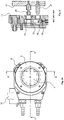
- the mould base 4 ( Figure 1b ) comprises a first member 5 and a second member 6.
- the first member 5 of blow mould base 4 which is also called bottom support, is the support member of the bottom impression 7 of the container to be blown.
- the second member 6 of blow mould base 4, also called collector or base plate, is designed to connect the bottom support or support member 5 to a positioning device 8 for positioning the mould base 4 along the longitudinal axis X of said mould.
- said positioning device 8 is represented by a carriage 9 which is movable along a track 10.
- the collector is made of a metal material, preferably but not necessarily aluminium.
- the support member 5 is provided, at a first end, with a housing for the bottom impression 7 of the container to be blown and, at a second end, with a flat surface 11.
- the support member 5 is further provided with the following components, protruding from said flat surface 11, which are useful for both the mechanical and hydraulic connection between said support member 5 and the collector 6:
- the second connection pin 21 is a tapered pin.
- the collector or base plate 6 is provided, at a flat surface 12 thereof facing the flat surface 11 of the support member 5, with:
- Both support member 5 and collector 6 are internally provided with respective ducts 23, 24, connected to the male elements 22 and to the female elements 22' of the fluid-tight connections, respectively, in order to allow the passage of a thermal conditioning liquid, e.g. water at a predetermined temperature, from the collector 6 to the bottom support and vice versa.
- a thermal conditioning liquid e.g. water at a predetermined temperature
- the two ducts 24 of the collector 6 allow the water to be conveyed from the external connections 25 to the female elements 22' of the fluid-tight connections and vice versa.
- FIG. 12 shows an example of push-fit, fluid-tight connection, which is commercially available and can be used in the present invention.
- the collector or base plate 6 is further internally provided with:
- First and second elastic return means 15, 18 are, preferably but not necessarily, helical compression springs. Other types of springs can alternatively be provided.
- the first slider 13, shown in Figure 11 is advantageously provided with:
- first connection pins 20 have a substantially mushroom- or cap-shaped end and the respective holes 27 of the first slider 13 have an eyelet-shaped profile for a quick and efficient mechanical coupling of said pins 20.
- first connection pins 20 ( Figure 2b ) have an end having a first, more internal, portion 50 having a first diameter, and a second, more external, portion 51, having a second diameter which is larger than the first diameter.
- the respective holes 27 of the first slider 13 have a first portion 52 having, in top plan, a first profile and a second portion 53 having, in top plan, a second profile which is narrower than the first profile ( Figure 11a ).
- connection pins 20 pass through the respective holes 27 at the portion 52 having a wider profile. After sliding of the first slider 13 outwards from the collector 6, the pins 20 are again locked with the second portion 51 thereof in the portion 53 of the holes 27 having a narrower profile.
- the second slider 16, shown in Figure 10 is advantageously provided with:
- the tapered pin 21 also functions as an anti-rotation device between bottom support and collector.
Landscapes
- Engineering & Computer Science (AREA)
- Mechanical Engineering (AREA)
- Manufacturing & Machinery (AREA)
- Moulds For Moulding Plastics Or The Like (AREA)
- Blow-Moulding Or Thermoforming Of Plastics Or The Like (AREA)
Claims (11)
- Blasform für Kunststoffbehälter, die eine Längsachse definiert und zumindest zwei laterale Halbformen und einen Formboden (4) aufweist,
wobei der Formboden (4) ein erstes Teil (5) und ein zweites Teil (6) aufweist, die mittels eines Schnellkupplungssystems miteinander verbunden werden können, das zumindest einen Verbindungsstift (20) aufweist, welcher Verbindungsstift (20) zwischen dem ersten Teil (5) und dem zweiten Teil (6) an dem ersten Teil (5) befestigt ist,
wobei das zweite Teil (6) darin enthält- einen ersten Schieber (13), der eine erste Längsgleitrichtung definiert entlang der ersten Richtung auf einer bezüglich der Längsachse senkrechten Ebene gleitet und eine entriegelte Position und eine verriegelte Position einnehmen kann, wobei der erste Schieber (13) mit zumindest einer Öffnung (27) versehen ist, um den zumindest einen Verbindungsstift (20) darin zu verriegeln, wenn der erste Schieber (13) in der verriegelten Position ist, und- einen zweiten Schieber (16), der eine zweite Längsgleitrichtung auf der Ebene definiert, die die erste Gleitrichtung schneidet; wobei der zweite Schieber (16) entlang der zweiten Gleitrichtung aus einer ersten Position in mechanischer Verbindung mit dem ersten Schieber (13), in der der erste Schieber (13) in der entriegelten Position ist, zu einer zweiten von dem ersten Schieber (13) entriegelten Position gleiten kann, wobei das erste Teil (5) und das zweite Teil (6) mittels des zumindest einen Verbindungsstifts (20) miteinander verbunden sind und der erste Schieber (13) in der verriegelten Position ist. - Blasform gemäß Anspruch 1, wobei das erste Teil (5) mit zwei ersten Verbindungsstiften (20) versehen ist und der erste Schieber (13) mit zwei Öffnungen (27) versehen ist, die entlang der ersten Längsgleitrichtung angeordnet sind und jede Öffnung (27) entsprechend geformt ist, um einen zugehörigen Verbindungsstift (20) zu verriegeln, wenn sich der erste Schieber (13) von der entriegelten Position zur verriegelten Position bewegt.
- Blasform gemäß Anspruch 1 oder 2, wobei das erste Teil (5) mit einem zweiten Verbindungsstift (21) zwischen dem ersten Teil und dem zweiten Teil versehen ist, der geeignet ist, um mit dem zweiten Schieber (16) zu interagieren, um diesen von der ersten Position der mechanischen Verbindung zu der zweiten, entriegelten, Position mitzunehmen.
- Blasform gemäß Anspruch 3, wobei im zweiten Teil (6) vorgesehen sind:- ein erstes internes Längsgehäuse, in dem der erste Schieber (13) gleiten kann,- erste elastische Rückholmittel (15), die mit einem ersten Ende am Boden des ersten internen Gehäuses und mit einem zweiten Ende am ersten Schieber (13) befestigt sind, um den ersten Schieber zur Verriegelungsposition zu drücken,- ein zweites internes Längsgehäuse, in dem der zweite Schieber (16) gleiten kann,- zweite elastische Rückholmittel (18), die mit einem ersten Ende am Boden des zweiten internen Gehäuses und mit einem zweiten Ende am zweiten Schieber (16) befestigt sind, um den zweiten Schieber zur ersten Position der mechanischen Verbindung zu drücken.
- Blasform gemäß Anspruch 3 oder 4, wobei zumindest eine flüssigkeitsdichte Schnellkupplungsverbindung zwischen dem ersten Teil (5) und dem zweiten Teil (6) vorgesehen ist, um eine Temperier-Flüssigkeit von dem zweiten Teil zum ersten Teil, und umgekehrt, weiterzuleiten.
- Blasform gemäß Anspruch 5, wobei die zumindest eine flüssigkeitsdichte Verbindung ein männliches Element (22), das aus dem ersten Teil (5) ragt, und ein weibliches Element (22'), das im zweiten Teil (6) im Eingriff steht, aufweist oder umgekehrt.
- Blasform gemäß Anspruch 5 oder 6, wobei zwei flüssigkeitsdichte Verbindungen vorgesehen sind.
- Blasform gemäß Anspruch 4, wobei zumindest ein erstes Durchgangsloch (20') auf einer Oberfläche des zweiten Teils (6) für den Eintritt des zumindest einen ersten Verbindungsstifts (20) in das erste interne Gehäuse vorgesehen ist.
- Blasform gemäß Anspruch 8, wobei zumindest ein zweites Durchgangsloch (21') auf einer Oberfläche des zweiten Teils (6) für den Eintritt des zweiten Verbindungsstifts (21) in das zweite interne Gehäuse vorgesehen ist.
- Blasform gemäß Anspruch 2, wobei die ersten Verbindungsstifte (20) ein Ende mit einem ersten Bereich (50), der einen ersten Durchmesser hat, und einen zweiten Bereich (51), der einen zweiten Durchmesser hat, der größer ist als der erste Durchmesser, wobei die zugehörigen Löcher (27) des ersten Schiebers (13) ein ösenförmiges Profil zum Einhaken der ersten Verbindungsstifte aufweisen.
- Blasform gemäß Anspruch 3, wobei der zweite Verbindungsstift (21) ein Kegelstift ist und der zweite Schieber (16) ein zugehöriges Durchgangsloch (31) mit einem Bereich einer Innenfläche (32), die derart geneigt ist, dass der Kegelstift während des Schrittes der Verbindung des ersten Teils (5) mit dem zweiten Teil (6) in den Bereich der Innenfläche eingreift, und somit die Entriegelung des zweiten Schiebers (16) vom ersten Schieber (13) bewerkstelligt.
Applications Claiming Priority (2)
| Application Number | Priority Date | Filing Date | Title |
|---|---|---|---|
| IT000126A ITRM20110126A1 (it) | 2011-03-16 | 2011-03-16 | Stampo di soffiaggio |
| PCT/EP2012/054649 WO2012123567A1 (en) | 2011-03-16 | 2012-03-16 | Blow mould |
Publications (2)
| Publication Number | Publication Date |
|---|---|
| EP2686151A1 EP2686151A1 (de) | 2014-01-22 |
| EP2686151B1 true EP2686151B1 (de) | 2018-07-04 |
Family
ID=43977356
Family Applications (1)
| Application Number | Title | Priority Date | Filing Date |
|---|---|---|---|
| EP12714246.1A Active EP2686151B1 (de) | 2011-03-16 | 2012-03-16 | Blasform |
Country Status (7)
| Country | Link |
|---|---|
| US (1) | US8915729B2 (de) |
| EP (1) | EP2686151B1 (de) |
| CN (1) | CN103534073B (de) |
| ES (1) | ES2689770T3 (de) |
| IT (1) | ITRM20110126A1 (de) |
| WO (1) | WO2012123567A1 (de) |
| ZA (1) | ZA201307697B (de) |
Cited By (1)
| Publication number | Priority date | Publication date | Assignee | Title |
|---|---|---|---|---|
| WO2025124825A1 (de) * | 2023-12-11 | 2025-06-19 | Khs Gmbh | Vorrichtung und system zum halten eines formwerkzeugsegments, handhabungsvorrichtung für ein formwerkzeugsegment und verfahren zum wechseln eines formwerkzeugsegments |
Families Citing this family (10)
| Publication number | Priority date | Publication date | Assignee | Title |
|---|---|---|---|---|
| ITRM20110165A1 (it) * | 2011-03-30 | 2012-10-01 | Sipa Progettazione Automaz | Stampo di soffiaggio |
| FR2983766B1 (fr) * | 2011-12-08 | 2014-02-14 | Sidel Participations | Ensemble pour la fixation, avec raccordement fluidique, d'un fond de moule sur un support |
| DE102012111497A1 (de) * | 2012-11-27 | 2014-05-28 | Gea Food Solutions Germany Gmbh | Verpackungsmaschine mit einer Komplettierungsanzeige |
| KR102205646B1 (ko) | 2015-03-17 | 2021-01-20 | 닛세이 에이. 에스. 비 기카이 가부시키가이샤 | 블로우몰드유닛 및 그를 사용한 블로우성형장치 |
| EP3661725B1 (de) | 2017-08-02 | 2022-01-19 | Krones AG | Automatischer blasformwechsel |
| WO2019067437A1 (en) * | 2017-09-29 | 2019-04-04 | F&S Tool, Inc. | BLIND INSTALLATION OF INJECTION MOLD ELEMENTS |
| IT201900006961A1 (it) * | 2019-05-17 | 2020-11-17 | Sipa Progettazione Automaz | Apparato di supporto per supportare almeno uno stampo di collo di contenitore in una macchina di stampaggio per iniezione e soffiaggio |
| CN111113858B (zh) * | 2019-12-19 | 2020-10-09 | 德玛克(长兴)注塑系统有限公司 | 一种吹瓶模快速锁模机构 |
| EP4335619A1 (de) * | 2022-09-08 | 2024-03-13 | Competek | Adapter zum befestigen eines formbodens an einem inkompatiblen formenträger |
| CN118927478B (zh) * | 2024-08-19 | 2025-12-26 | 江苏新美星包装机械股份有限公司 | 一种模具快换装置 |
Family Cites Families (9)
| Publication number | Priority date | Publication date | Assignee | Title |
|---|---|---|---|---|
| FR2733176B1 (fr) * | 1995-04-19 | 1997-06-27 | Sidel Sa | Dispositif pour fabriquer des recipients en une matiere thermoplastique par soufflage ou etirage-soufflage |
| DE10033412B4 (de) | 2000-07-08 | 2012-05-24 | Khs Corpoplast Gmbh | Vorrichtung zur Blasformung von Behältern |
| US7014446B2 (en) * | 2003-07-14 | 2006-03-21 | Uniloy Milacron Inc. | Quick release volume control inserts for molding machines |
| DE102005035233A1 (de) * | 2005-07-25 | 2007-04-12 | Sig Technology Ag | Vorrichtung zur Halterung von Blasformsegmenten |
| CN201165036Y (zh) * | 2007-10-31 | 2008-12-17 | 深圳Tcl新技术有限公司 | 模具镶件快换结构 |
| US8057210B2 (en) * | 2009-04-29 | 2011-11-15 | Visy R & D Pty Ltd | Mould insert |
| DE102009035871A1 (de) * | 2009-07-31 | 2011-02-03 | Krones Ag | Schnellwechselmechansimus für Bodenteile |
| EP2292409B1 (de) * | 2009-09-04 | 2011-11-16 | Uhlmann Pac-Systeme GmbH & Co. KG | Werkzeugträger, Werkzeug und Arbeitsstation mit Werkzeugträger und daran befestigtem Werkzeug |
| DE102010048720A1 (de) * | 2010-10-19 | 2012-04-19 | Krones Aktiengesellschaft | Schnellmontierbare Bodenform mit zuschaltbarer Haltekraftunterstützung |
-
2011
- 2011-03-16 IT IT000126A patent/ITRM20110126A1/it unknown
-
2012
- 2012-03-16 CN CN201280023250.6A patent/CN103534073B/zh active Active
- 2012-03-16 EP EP12714246.1A patent/EP2686151B1/de active Active
- 2012-03-16 WO PCT/EP2012/054649 patent/WO2012123567A1/en not_active Ceased
- 2012-03-16 US US14/005,485 patent/US8915729B2/en active Active
- 2012-03-16 ES ES12714246.1T patent/ES2689770T3/es active Active
-
2013
- 2013-10-16 ZA ZA2013/07697A patent/ZA201307697B/en unknown
Non-Patent Citations (1)
| Title |
|---|
| None * |
Cited By (1)
| Publication number | Priority date | Publication date | Assignee | Title |
|---|---|---|---|---|
| WO2025124825A1 (de) * | 2023-12-11 | 2025-06-19 | Khs Gmbh | Vorrichtung und system zum halten eines formwerkzeugsegments, handhabungsvorrichtung für ein formwerkzeugsegment und verfahren zum wechseln eines formwerkzeugsegments |
Also Published As
| Publication number | Publication date |
|---|---|
| US8915729B2 (en) | 2014-12-23 |
| ZA201307697B (en) | 2014-07-30 |
| EP2686151A1 (de) | 2014-01-22 |
| CN103534073A (zh) | 2014-01-22 |
| US20140010910A1 (en) | 2014-01-09 |
| ITRM20110126A1 (it) | 2012-09-17 |
| WO2012123567A1 (en) | 2012-09-20 |
| CN103534073B (zh) | 2016-01-20 |
| ES2689770T3 (es) | 2018-11-15 |
Similar Documents
| Publication | Publication Date | Title |
|---|---|---|
| EP2686151B1 (de) | Blasform | |
| CN102481720B (zh) | 模具更换方法 | |
| CN103459123B (zh) | 吹塑模具 | |
| US20130224328A1 (en) | Demolding mechanism for molded article having internal thread | |
| JP2005045248A (ja) | 光送受信モジュールのホットプラギング装置 | |
| CN110841967A (zh) | 一种模具加工用表面清洗装置 | |
| JP2009262418A (ja) | 金型装置 | |
| CN100546810C (zh) | 用于容器吹塑机的模具及用一该模具来制造容器的方法 | |
| CN206485482U (zh) | 一种自锁机构 | |
| JPWO2020174615A1 (ja) | アンダーカット処理機構、成形用金型及び成形品 | |
| JP2020015211A (ja) | アンダーカット処理機構及び成形用金型 | |
| CN111037853B (zh) | 氧合器螺旋导流内芯注塑成型模具 | |
| CN119704130A (zh) | 一种工具盒 | |
| JP2658558B2 (ja) | 射出成形金型のエジェクタプレートのロック装置 | |
| CN201115984Y (zh) | 开\合模定位机构 | |
| CN205291439U (zh) | 注塑模具 | |
| CN214294211U (zh) | 模具组件及模具 | |
| CN104228001B (zh) | 注塑模具 | |
| JP2004142286A (ja) | 湾曲物の射出成形金型及びその離型方法 | |
| CN210308833U (zh) | 一种模具内圆柱扣位二次强脱结构 | |
| CN222809354U (zh) | 一种便于清理的模压生产装置 | |
| CN206465407U (zh) | 注塑模具二次顶出机构及注塑模具 | |
| CN201120683Y (zh) | 具滑块机构的模具 | |
| CN206983164U (zh) | 注塑模具 | |
| CN218196347U (zh) | 成型模具 |
Legal Events
| Date | Code | Title | Description |
|---|---|---|---|
| PUAI | Public reference made under article 153(3) epc to a published international application that has entered the european phase |
Free format text: ORIGINAL CODE: 0009012 |
|
| 17P | Request for examination filed |
Effective date: 20131015 |
|
| AK | Designated contracting states |
Kind code of ref document: A1 Designated state(s): AL AT BE BG CH CY CZ DE DK EE ES FI FR GB GR HR HU IE IS IT LI LT LU LV MC MK MT NL NO PL PT RO RS SE SI SK SM TR |
|
| DAX | Request for extension of the european patent (deleted) | ||
| GRAP | Despatch of communication of intention to grant a patent |
Free format text: ORIGINAL CODE: EPIDOSNIGR1 |
|
| STAA | Information on the status of an ep patent application or granted ep patent |
Free format text: STATUS: GRANT OF PATENT IS INTENDED |
|
| INTG | Intention to grant announced |
Effective date: 20180119 |
|
| GRAS | Grant fee paid |
Free format text: ORIGINAL CODE: EPIDOSNIGR3 |
|
| GRAA | (expected) grant |
Free format text: ORIGINAL CODE: 0009210 |
|
| STAA | Information on the status of an ep patent application or granted ep patent |
Free format text: STATUS: THE PATENT HAS BEEN GRANTED |
|
| AK | Designated contracting states |
Kind code of ref document: B1 Designated state(s): AL AT BE BG CH CY CZ DE DK EE ES FI FR GB GR HR HU IE IS IT LI LT LU LV MC MK MT NL NO PL PT RO RS SE SI SK SM TR |
|
| REG | Reference to a national code |
Ref country code: GB Ref legal event code: FG4D |
|
| REG | Reference to a national code |
Ref country code: CH Ref legal event code: EP |
|
| REG | Reference to a national code |
Ref country code: AT Ref legal event code: REF Ref document number: 1014020 Country of ref document: AT Kind code of ref document: T Effective date: 20180715 |
|
| REG | Reference to a national code |
Ref country code: IE Ref legal event code: FG4D |
|
| REG | Reference to a national code |
Ref country code: DE Ref legal event code: R096 Ref document number: 602012048044 Country of ref document: DE |
|
| REG | Reference to a national code |
Ref country code: RO Ref legal event code: EPE |
|
| REG | Reference to a national code |
Ref country code: NL Ref legal event code: MP Effective date: 20180704 |
|
| REG | Reference to a national code |
Ref country code: ES Ref legal event code: FG2A Ref document number: 2689770 Country of ref document: ES Kind code of ref document: T3 Effective date: 20181115 |
|
| REG | Reference to a national code |
Ref country code: LT Ref legal event code: MG4D |
|
| PG25 | Lapsed in a contracting state [announced via postgrant information from national office to epo] |
Ref country code: NL Free format text: LAPSE BECAUSE OF FAILURE TO SUBMIT A TRANSLATION OF THE DESCRIPTION OR TO PAY THE FEE WITHIN THE PRESCRIBED TIME-LIMIT Effective date: 20180704 |
|
| PG25 | Lapsed in a contracting state [announced via postgrant information from national office to epo] |
Ref country code: CZ Free format text: LAPSE BECAUSE OF FAILURE TO SUBMIT A TRANSLATION OF THE DESCRIPTION OR TO PAY THE FEE WITHIN THE PRESCRIBED TIME-LIMIT Effective date: 20180704 Ref country code: FI Free format text: LAPSE BECAUSE OF FAILURE TO SUBMIT A TRANSLATION OF THE DESCRIPTION OR TO PAY THE FEE WITHIN THE PRESCRIBED TIME-LIMIT Effective date: 20180704 Ref country code: NO Free format text: LAPSE BECAUSE OF FAILURE TO SUBMIT A TRANSLATION OF THE DESCRIPTION OR TO PAY THE FEE WITHIN THE PRESCRIBED TIME-LIMIT Effective date: 20181004 Ref country code: IS Free format text: LAPSE BECAUSE OF FAILURE TO SUBMIT A TRANSLATION OF THE DESCRIPTION OR TO PAY THE FEE WITHIN THE PRESCRIBED TIME-LIMIT Effective date: 20181104 Ref country code: RS Free format text: LAPSE BECAUSE OF FAILURE TO SUBMIT A TRANSLATION OF THE DESCRIPTION OR TO PAY THE FEE WITHIN THE PRESCRIBED TIME-LIMIT Effective date: 20180704 Ref country code: SE Free format text: LAPSE BECAUSE OF FAILURE TO SUBMIT A TRANSLATION OF THE DESCRIPTION OR TO PAY THE FEE WITHIN THE PRESCRIBED TIME-LIMIT Effective date: 20180704 Ref country code: BG Free format text: LAPSE BECAUSE OF FAILURE TO SUBMIT A TRANSLATION OF THE DESCRIPTION OR TO PAY THE FEE WITHIN THE PRESCRIBED TIME-LIMIT Effective date: 20181004 Ref country code: LT Free format text: LAPSE BECAUSE OF FAILURE TO SUBMIT A TRANSLATION OF THE DESCRIPTION OR TO PAY THE FEE WITHIN THE PRESCRIBED TIME-LIMIT Effective date: 20180704 Ref country code: GR Free format text: LAPSE BECAUSE OF FAILURE TO SUBMIT A TRANSLATION OF THE DESCRIPTION OR TO PAY THE FEE WITHIN THE PRESCRIBED TIME-LIMIT Effective date: 20181005 Ref country code: PL Free format text: LAPSE BECAUSE OF FAILURE TO SUBMIT A TRANSLATION OF THE DESCRIPTION OR TO PAY THE FEE WITHIN THE PRESCRIBED TIME-LIMIT Effective date: 20180704 |
|
| PG25 | Lapsed in a contracting state [announced via postgrant information from national office to epo] |
Ref country code: AL Free format text: LAPSE BECAUSE OF FAILURE TO SUBMIT A TRANSLATION OF THE DESCRIPTION OR TO PAY THE FEE WITHIN THE PRESCRIBED TIME-LIMIT Effective date: 20180704 Ref country code: LV Free format text: LAPSE BECAUSE OF FAILURE TO SUBMIT A TRANSLATION OF THE DESCRIPTION OR TO PAY THE FEE WITHIN THE PRESCRIBED TIME-LIMIT Effective date: 20180704 Ref country code: HR Free format text: LAPSE BECAUSE OF FAILURE TO SUBMIT A TRANSLATION OF THE DESCRIPTION OR TO PAY THE FEE WITHIN THE PRESCRIBED TIME-LIMIT Effective date: 20180704 |
|
| REG | Reference to a national code |
Ref country code: DE Ref legal event code: R097 Ref document number: 602012048044 Country of ref document: DE |
|
| PG25 | Lapsed in a contracting state [announced via postgrant information from national office to epo] |
Ref country code: EE Free format text: LAPSE BECAUSE OF FAILURE TO SUBMIT A TRANSLATION OF THE DESCRIPTION OR TO PAY THE FEE WITHIN THE PRESCRIBED TIME-LIMIT Effective date: 20180704 |
|
| PLBE | No opposition filed within time limit |
Free format text: ORIGINAL CODE: 0009261 |
|
| STAA | Information on the status of an ep patent application or granted ep patent |
Free format text: STATUS: NO OPPOSITION FILED WITHIN TIME LIMIT |
|
| PG25 | Lapsed in a contracting state [announced via postgrant information from national office to epo] |
Ref country code: SM Free format text: LAPSE BECAUSE OF FAILURE TO SUBMIT A TRANSLATION OF THE DESCRIPTION OR TO PAY THE FEE WITHIN THE PRESCRIBED TIME-LIMIT Effective date: 20180704 Ref country code: DK Free format text: LAPSE BECAUSE OF FAILURE TO SUBMIT A TRANSLATION OF THE DESCRIPTION OR TO PAY THE FEE WITHIN THE PRESCRIBED TIME-LIMIT Effective date: 20180704 Ref country code: SK Free format text: LAPSE BECAUSE OF FAILURE TO SUBMIT A TRANSLATION OF THE DESCRIPTION OR TO PAY THE FEE WITHIN THE PRESCRIBED TIME-LIMIT Effective date: 20180704 |
|
| 26N | No opposition filed |
Effective date: 20190405 |
|
| PG25 | Lapsed in a contracting state [announced via postgrant information from national office to epo] |
Ref country code: SI Free format text: LAPSE BECAUSE OF FAILURE TO SUBMIT A TRANSLATION OF THE DESCRIPTION OR TO PAY THE FEE WITHIN THE PRESCRIBED TIME-LIMIT Effective date: 20180704 |
|
| PG25 | Lapsed in a contracting state [announced via postgrant information from national office to epo] |
Ref country code: RO Free format text: LAPSE BECAUSE OF NON-PAYMENT OF DUE FEES Effective date: 20180704 Ref country code: MC Free format text: LAPSE BECAUSE OF FAILURE TO SUBMIT A TRANSLATION OF THE DESCRIPTION OR TO PAY THE FEE WITHIN THE PRESCRIBED TIME-LIMIT Effective date: 20180704 |
|
| REG | Reference to a national code |
Ref country code: CH Ref legal event code: PL |
|
| GBPC | Gb: european patent ceased through non-payment of renewal fee |
Effective date: 20190316 |
|
| PG25 | Lapsed in a contracting state [announced via postgrant information from national office to epo] |
Ref country code: LU Free format text: LAPSE BECAUSE OF NON-PAYMENT OF DUE FEES Effective date: 20190316 |
|
| REG | Reference to a national code |
Ref country code: BE Ref legal event code: MM Effective date: 20190331 |
|
| PG25 | Lapsed in a contracting state [announced via postgrant information from national office to epo] |
Ref country code: LI Free format text: LAPSE BECAUSE OF NON-PAYMENT OF DUE FEES Effective date: 20190331 Ref country code: CH Free format text: LAPSE BECAUSE OF NON-PAYMENT OF DUE FEES Effective date: 20190331 Ref country code: IE Free format text: LAPSE BECAUSE OF NON-PAYMENT OF DUE FEES Effective date: 20190316 Ref country code: GB Free format text: LAPSE BECAUSE OF NON-PAYMENT OF DUE FEES Effective date: 20190316 |
|
| PG25 | Lapsed in a contracting state [announced via postgrant information from national office to epo] |
Ref country code: BE Free format text: LAPSE BECAUSE OF NON-PAYMENT OF DUE FEES Effective date: 20190331 |
|
| PG25 | Lapsed in a contracting state [announced via postgrant information from national office to epo] |
Ref country code: MT Free format text: LAPSE BECAUSE OF NON-PAYMENT OF DUE FEES Effective date: 20190316 Ref country code: PT Free format text: LAPSE BECAUSE OF FAILURE TO SUBMIT A TRANSLATION OF THE DESCRIPTION OR TO PAY THE FEE WITHIN THE PRESCRIBED TIME-LIMIT Effective date: 20181105 |
|
| PG25 | Lapsed in a contracting state [announced via postgrant information from national office to epo] |
Ref country code: CY Free format text: LAPSE BECAUSE OF FAILURE TO SUBMIT A TRANSLATION OF THE DESCRIPTION OR TO PAY THE FEE WITHIN THE PRESCRIBED TIME-LIMIT Effective date: 20180704 |
|
| PG25 | Lapsed in a contracting state [announced via postgrant information from national office to epo] |
Ref country code: HU Free format text: LAPSE BECAUSE OF FAILURE TO SUBMIT A TRANSLATION OF THE DESCRIPTION OR TO PAY THE FEE WITHIN THE PRESCRIBED TIME-LIMIT; INVALID AB INITIO Effective date: 20120316 |
|
| REG | Reference to a national code |
Ref country code: AT Ref legal event code: UEP Ref document number: 1014020 Country of ref document: AT Kind code of ref document: T Effective date: 20180704 |
|
| PG25 | Lapsed in a contracting state [announced via postgrant information from national office to epo] |
Ref country code: MK Free format text: LAPSE BECAUSE OF FAILURE TO SUBMIT A TRANSLATION OF THE DESCRIPTION OR TO PAY THE FEE WITHIN THE PRESCRIBED TIME-LIMIT Effective date: 20180704 |
|
| P01 | Opt-out of the competence of the unified patent court (upc) registered |
Effective date: 20230525 |
|
| PGFP | Annual fee paid to national office [announced via postgrant information from national office to epo] |
Ref country code: DE Payment date: 20250319 Year of fee payment: 14 |
|
| PGFP | Annual fee paid to national office [announced via postgrant information from national office to epo] |
Ref country code: TR Payment date: 20250310 Year of fee payment: 14 |
|
| PGFP | Annual fee paid to national office [announced via postgrant information from national office to epo] |
Ref country code: ES Payment date: 20250428 Year of fee payment: 14 |
|
| PGFP | Annual fee paid to national office [announced via postgrant information from national office to epo] |
Ref country code: IT Payment date: 20250331 Year of fee payment: 14 |
|
| PGFP | Annual fee paid to national office [announced via postgrant information from national office to epo] |
Ref country code: AT Payment date: 20260324 Year of fee payment: 15 |
|
| PGFP | Annual fee paid to national office [announced via postgrant information from national office to epo] |
Ref country code: FR Payment date: 20260330 Year of fee payment: 15 |