EP2686481B1 - Klingenförmiges werkzeug und verfahren zu seiner herstellung - Google Patents
Klingenförmiges werkzeug und verfahren zu seiner herstellung Download PDFInfo
- Publication number
- EP2686481B1 EP2686481B1 EP12761451.9A EP12761451A EP2686481B1 EP 2686481 B1 EP2686481 B1 EP 2686481B1 EP 12761451 A EP12761451 A EP 12761451A EP 2686481 B1 EP2686481 B1 EP 2686481B1
- Authority
- EP
- European Patent Office
- Prior art keywords
- steel
- hardness
- ion implantation
- tool
- plasma immersion
- Prior art date
- Legal status (The legal status is an assumption and is not a legal conclusion. Google has not performed a legal analysis and makes no representation as to the accuracy of the status listed.)
- Active
Links
Images



Classifications
-
- B—PERFORMING OPERATIONS; TRANSPORTING
- B41—PRINTING; LINING MACHINES; TYPEWRITERS; STAMPS
- B41F—PRINTING MACHINES OR PRESSES
- B41F31/00—Inking arrangements or devices
- B41F31/02—Ducts, containers, supply or metering devices
- B41F31/04—Ducts, containers, supply or metering devices with duct-blades or like metering devices
-
- D—TEXTILES; PAPER
- D21—PAPER-MAKING; PRODUCTION OF CELLULOSE
- D21G—CALENDERS; ACCESSORIES FOR PAPER-MAKING MACHINES
- D21G3/00—Doctors
-
- A—HUMAN NECESSITIES
- A61—MEDICAL OR VETERINARY SCIENCE; HYGIENE
- A61B—DIAGNOSIS; SURGERY; IDENTIFICATION
- A61B17/00—Surgical instruments, devices or methods
- A61B17/32—Surgical cutting instruments
-
- B—PERFORMING OPERATIONS; TRANSPORTING
- B05—SPRAYING OR ATOMISING IN GENERAL; APPLYING FLUENT MATERIALS TO SURFACES, IN GENERAL
- B05C—APPARATUS FOR APPLYING FLUENT MATERIALS TO SURFACES, IN GENERAL
- B05C11/00—Component parts, details or accessories not specifically provided for in groups B05C1/00 - B05C9/00
- B05C11/02—Apparatus for spreading or distributing liquids or other fluent materials already applied to a surface ; Controlling means therefor; Control of the thickness of a coating by spreading or distributing liquids or other fluent materials already applied to the coated surface
- B05C11/04—Apparatus for spreading or distributing liquids or other fluent materials already applied to a surface ; Controlling means therefor; Control of the thickness of a coating by spreading or distributing liquids or other fluent materials already applied to the coated surface with blades
-
- B—PERFORMING OPERATIONS; TRANSPORTING
- B05—SPRAYING OR ATOMISING IN GENERAL; APPLYING FLUENT MATERIALS TO SURFACES, IN GENERAL
- B05C—APPARATUS FOR APPLYING FLUENT MATERIALS TO SURFACES, IN GENERAL
- B05C11/00—Component parts, details or accessories not specifically provided for in groups B05C1/00 - B05C9/00
- B05C11/02—Apparatus for spreading or distributing liquids or other fluent materials already applied to a surface ; Controlling means therefor; Control of the thickness of a coating by spreading or distributing liquids or other fluent materials already applied to the coated surface
- B05C11/04—Apparatus for spreading or distributing liquids or other fluent materials already applied to a surface ; Controlling means therefor; Control of the thickness of a coating by spreading or distributing liquids or other fluent materials already applied to the coated surface with blades
- B05C11/045—Apparatus for spreading or distributing liquids or other fluent materials already applied to a surface ; Controlling means therefor; Control of the thickness of a coating by spreading or distributing liquids or other fluent materials already applied to the coated surface with blades characterised by the blades themselves
-
- B—PERFORMING OPERATIONS; TRANSPORTING
- B23—MACHINE TOOLS; METAL-WORKING NOT OTHERWISE PROVIDED FOR
- B23D—PLANING; SLOTTING; SHEARING; BROACHING; SAWING; FILING; SCRAPING; LIKE OPERATIONS FOR WORKING METAL BY REMOVING MATERIAL, NOT OTHERWISE PROVIDED FOR
- B23D35/00—Tools for shearing machines or shearing devices; Holders or chucks for shearing tools
-
- B—PERFORMING OPERATIONS; TRANSPORTING
- B26—HAND CUTTING TOOLS; CUTTING; SEVERING
- B26B—HAND-HELD CUTTING TOOLS NOT OTHERWISE PROVIDED FOR
- B26B9/00—Blades for hand knives
-
- B—PERFORMING OPERATIONS; TRANSPORTING
- B31—MAKING ARTICLES OF PAPER, CARDBOARD OR MATERIAL WORKED IN A MANNER ANALOGOUS TO PAPER; WORKING PAPER, CARDBOARD OR MATERIAL WORKED IN A MANNER ANALOGOUS TO PAPER
- B31F—MECHANICAL WORKING OR DEFORMATION OF PAPER, CARDBOARD OR MATERIAL WORKED IN A MANNER ANALOGOUS TO PAPER
- B31F1/00—Mechanical deformation without removing material, e.g. in combination with laminating
- B31F1/12—Crêping
- B31F1/14—Crêping by doctor blades arranged crosswise to the web
- B31F1/145—Blade constructions
-
- B—PERFORMING OPERATIONS; TRANSPORTING
- B41—PRINTING; LINING MACHINES; TYPEWRITERS; STAMPS
- B41F—PRINTING MACHINES OR PRESSES
- B41F9/00—Rotary intaglio printing presses
- B41F9/06—Details
- B41F9/08—Wiping mechanisms
- B41F9/10—Doctors, scrapers, or like devices
-
- C—CHEMISTRY; METALLURGY
- C21—METALLURGY OF IRON
- C21D—MODIFYING THE PHYSICAL STRUCTURE OF FERROUS METALS; GENERAL DEVICES FOR HEAT TREATMENT OF FERROUS OR NON-FERROUS METALS OR ALLOYS; MAKING METAL MALLEABLE, e.g. BY DECARBURISATION OR TEMPERING
- C21D9/00—Heat treatment, e.g. annealing, hardening, quenching or tempering, adapted for particular articles; Furnaces therefor
- C21D9/18—Heat treatment, e.g. annealing, hardening, quenching or tempering, adapted for particular articles; Furnaces therefor for knives, scythes, scissors, or like hand cutting tools
-
- C—CHEMISTRY; METALLURGY
- C22—METALLURGY; FERROUS OR NON-FERROUS ALLOYS; TREATMENT OF ALLOYS OR NON-FERROUS METALS
- C22C—ALLOYS
- C22C38/00—Ferrous alloys, e.g. steel alloys
- C22C38/02—Ferrous alloys, e.g. steel alloys containing silicon
-
- C—CHEMISTRY; METALLURGY
- C22—METALLURGY; FERROUS OR NON-FERROUS ALLOYS; TREATMENT OF ALLOYS OR NON-FERROUS METALS
- C22C—ALLOYS
- C22C38/00—Ferrous alloys, e.g. steel alloys
- C22C38/04—Ferrous alloys, e.g. steel alloys containing manganese
-
- C—CHEMISTRY; METALLURGY
- C22—METALLURGY; FERROUS OR NON-FERROUS ALLOYS; TREATMENT OF ALLOYS OR NON-FERROUS METALS
- C22C—ALLOYS
- C22C38/00—Ferrous alloys, e.g. steel alloys
- C22C38/18—Ferrous alloys, e.g. steel alloys containing chromium
-
- C—CHEMISTRY; METALLURGY
- C22—METALLURGY; FERROUS OR NON-FERROUS ALLOYS; TREATMENT OF ALLOYS OR NON-FERROUS METALS
- C22C—ALLOYS
- C22C38/00—Ferrous alloys, e.g. steel alloys
- C22C38/18—Ferrous alloys, e.g. steel alloys containing chromium
- C22C38/22—Ferrous alloys, e.g. steel alloys containing chromium with molybdenum or tungsten
-
- C—CHEMISTRY; METALLURGY
- C22—METALLURGY; FERROUS OR NON-FERROUS ALLOYS; TREATMENT OF ALLOYS OR NON-FERROUS METALS
- C22C—ALLOYS
- C22C38/00—Ferrous alloys, e.g. steel alloys
- C22C38/18—Ferrous alloys, e.g. steel alloys containing chromium
- C22C38/24—Ferrous alloys, e.g. steel alloys containing chromium with vanadium
-
- C—CHEMISTRY; METALLURGY
- C23—COATING METALLIC MATERIAL; COATING MATERIAL WITH METALLIC MATERIAL; CHEMICAL SURFACE TREATMENT; DIFFUSION TREATMENT OF METALLIC MATERIAL; COATING BY VACUUM EVAPORATION, BY SPUTTERING, BY ION IMPLANTATION OR BY CHEMICAL VAPOUR DEPOSITION, IN GENERAL; INHIBITING CORROSION OF METALLIC MATERIAL OR INCRUSTATION IN GENERAL
- C23C—COATING METALLIC MATERIAL; COATING MATERIAL WITH METALLIC MATERIAL; SURFACE TREATMENT OF METALLIC MATERIAL BY DIFFUSION INTO THE SURFACE, BY CHEMICAL CONVERSION OR SUBSTITUTION; COATING BY VACUUM EVAPORATION, BY SPUTTERING, BY ION IMPLANTATION OR BY CHEMICAL VAPOUR DEPOSITION, IN GENERAL
- C23C14/00—Coating by vacuum evaporation, by sputtering or by ion implantation of the coating forming material
- C23C14/06—Coating by vacuum evaporation, by sputtering or by ion implantation of the coating forming material characterised by the coating material
- C23C14/0635—Carbides
-
- C—CHEMISTRY; METALLURGY
- C23—COATING METALLIC MATERIAL; COATING MATERIAL WITH METALLIC MATERIAL; CHEMICAL SURFACE TREATMENT; DIFFUSION TREATMENT OF METALLIC MATERIAL; COATING BY VACUUM EVAPORATION, BY SPUTTERING, BY ION IMPLANTATION OR BY CHEMICAL VAPOUR DEPOSITION, IN GENERAL; INHIBITING CORROSION OF METALLIC MATERIAL OR INCRUSTATION IN GENERAL
- C23C—COATING METALLIC MATERIAL; COATING MATERIAL WITH METALLIC MATERIAL; SURFACE TREATMENT OF METALLIC MATERIAL BY DIFFUSION INTO THE SURFACE, BY CHEMICAL CONVERSION OR SUBSTITUTION; COATING BY VACUUM EVAPORATION, BY SPUTTERING, BY ION IMPLANTATION OR BY CHEMICAL VAPOUR DEPOSITION, IN GENERAL
- C23C14/00—Coating by vacuum evaporation, by sputtering or by ion implantation of the coating forming material
- C23C14/06—Coating by vacuum evaporation, by sputtering or by ion implantation of the coating forming material characterised by the coating material
- C23C14/0641—Nitrides
-
- C—CHEMISTRY; METALLURGY
- C23—COATING METALLIC MATERIAL; COATING MATERIAL WITH METALLIC MATERIAL; CHEMICAL SURFACE TREATMENT; DIFFUSION TREATMENT OF METALLIC MATERIAL; COATING BY VACUUM EVAPORATION, BY SPUTTERING, BY ION IMPLANTATION OR BY CHEMICAL VAPOUR DEPOSITION, IN GENERAL; INHIBITING CORROSION OF METALLIC MATERIAL OR INCRUSTATION IN GENERAL
- C23C—COATING METALLIC MATERIAL; COATING MATERIAL WITH METALLIC MATERIAL; SURFACE TREATMENT OF METALLIC MATERIAL BY DIFFUSION INTO THE SURFACE, BY CHEMICAL CONVERSION OR SUBSTITUTION; COATING BY VACUUM EVAPORATION, BY SPUTTERING, BY ION IMPLANTATION OR BY CHEMICAL VAPOUR DEPOSITION, IN GENERAL
- C23C14/00—Coating by vacuum evaporation, by sputtering or by ion implantation of the coating forming material
- C23C14/22—Coating by vacuum evaporation, by sputtering or by ion implantation of the coating forming material characterised by the process of coating
- C23C14/48—Ion implantation
-
- D—TEXTILES; PAPER
- D21—PAPER-MAKING; PRODUCTION OF CELLULOSE
- D21G—CALENDERS; ACCESSORIES FOR PAPER-MAKING MACHINES
- D21G3/00—Doctors
- D21G3/005—Doctor knifes
-
- D—TEXTILES; PAPER
- D21—PAPER-MAKING; PRODUCTION OF CELLULOSE
- D21H—PULP COMPOSITIONS; PREPARATION THEREOF NOT COVERED BY SUBCLASSES D21C OR D21D; IMPREGNATING OR COATING OF PAPER; TREATMENT OF FINISHED PAPER NOT COVERED BY CLASS B31 OR SUBCLASS D21G; PAPER NOT OTHERWISE PROVIDED FOR
- D21H23/00—Processes or apparatus for adding material to the pulp or to the paper
- D21H23/02—Processes or apparatus for adding material to the pulp or to the paper characterised by the manner in which substances are added
- D21H23/22—Addition to the formed paper
- D21H23/32—Addition to the formed paper by contacting paper with an excess of material, e.g. from a reservoir or in a manner necessitating removal of applied excess material from the paper
- D21H23/34—Knife or blade type coaters
-
- D—TEXTILES; PAPER
- D21—PAPER-MAKING; PRODUCTION OF CELLULOSE
- D21H—PULP COMPOSITIONS; PREPARATION THEREOF NOT COVERED BY SUBCLASSES D21C OR D21D; IMPREGNATING OR COATING OF PAPER; TREATMENT OF FINISHED PAPER NOT COVERED BY CLASS B31 OR SUBCLASS D21G; PAPER NOT OTHERWISE PROVIDED FOR
- D21H27/00—Special paper not otherwise provided for, e.g. made by multi-step processes
- D21H27/30—Multi-ply
- D21H27/40—Multi-ply at least one of the sheets being non-planar, e.g. crêped
-
- A—HUMAN NECESSITIES
- A61—MEDICAL OR VETERINARY SCIENCE; HYGIENE
- A61B—DIAGNOSIS; SURGERY; IDENTIFICATION
- A61B17/00—Surgical instruments, devices or methods
- A61B17/32—Surgical cutting instruments
- A61B17/3209—Incision instruments
- A61B17/3211—Surgical scalpels, knives; Accessories therefor
-
- A—HUMAN NECESSITIES
- A61—MEDICAL OR VETERINARY SCIENCE; HYGIENE
- A61B—DIAGNOSIS; SURGERY; IDENTIFICATION
- A61B17/00—Surgical instruments, devices or methods
- A61B2017/00526—Methods of manufacturing
-
- A—HUMAN NECESSITIES
- A61—MEDICAL OR VETERINARY SCIENCE; HYGIENE
- A61B—DIAGNOSIS; SURGERY; IDENTIFICATION
- A61B17/00—Surgical instruments, devices or methods
- A61B2017/00831—Material properties
Definitions
- the invention relates to a blade shaped tool belonging to that type of tools which comprises flat, strip shaped doctor and coater blades, which have a body of steel and at least one end portion, which is the working part of the tool during use thereof.
- Blade shaped tools of many kinds are employed for various industrial applications. Doctor blades of the typed mentioned in the preamble are used in printing offices and printeries for scraping excess ink from an engraved printing or ductor roller. In the paper industry, coater blades, which also are made of strip steel of the above mentioned kind, are employed for scraping excess coating material from a running paper web in order to leave just an even layer of coating material of desired thickness on the web. Further, also crêping doctor blades for crêping a paper web should be mentioned in this connection. I all these cases, high quality requirements are raised on the employed blade shaped tools, which preferably are made of strip steel. They need to have, for their respective fields of use, an adequate thickness, width, length and shape, flexibility, hardness, and resistance to wear. Particularly, the combination of all these requirements have been difficult to satisfy.
- WO00/13860 discloses hardening of cutter knife edges by Plasma Ion Implantation of foreign ions comprising N, C, Mo, T or Ti.
- burr i.e. tiny projections which may develop on the trailing side of the tool, which may cause scratches or other damages on gravure printing cylinders and anilox rolls for flexographic printing, as well as defects on the web material, respectively, or other damages or defects of various kinds if the "burr" material would come loose.
- the invention aims at providing a thin, improved blade shaped tool which advantageously combines a high wear resistance with a high stiffness against bending, allowing the tool the be pressed with a high contact pressure against the object to be doctored or coated.
- the four blade shaped tools according to the invention whose profiles are shown in Fig. 1 - Fig. 4 , are designated 1, 2, 3, and 4, respectively.
- a hardenable, cold-rolled strip steel for example any of those types of material which today conventionally are used for the manufacturing of doctor and/or coater blades, such as cold-rolled strips of carbon steel, low-alloyed hardenable steels or stainless, martensitic chromium steels.
- the steels in the tools 1-4 have in their hardened and tempered condition a hardness between 500 and 700 HN (Hardness Vickers).
- the body 5 of the tools 1-4 i.e. their main portion, has a thickness which typically is between 0.07 and 0.4 mm as far as doctor blades is concerned, while coater blades typically has a thickness between 0.3 and 0.6 mm.
- the width is typically about 10 - 100 mm.
- the length can be up to about three to four meters, or more in exceptional cases, but may also, as far as doctor blades for printeries are concerned, be as short as 10 cm.
- each of the two wide sides of the blade shaped tool has a surface layer 6a and 6b, respectively, Fig. 5 , which contains hardness increasing products which are precipitated in the matrix of the steel near the surface although to a certain depth. All surfaces of the tool, according to the embodiment, are covered by such surface layers, which are very hard. It is particularly important that the two wide sides 10a and 10b are covered by the hard surface layers 6a, 6b, which are well integrated with the steel body 5, such that they will possess a high tensile strength.
- Fig. 1A illustrates schematically the appearance of the working edge portion when its outermost tip - e.g.
- the surface layers 6a, 6b consist of components from the base material of the doctor blade, i.e. the strip steel which the doctor blade is made mainly of, and of hard products which have been incorporated in the surface layers.
- the hard products in said surface layers consist, according to the invention, mainly of hard products of reaction between, on one hand, one or more of the agents nitrogen, oxygen, and carbon and, on the other hand, one or more reactive metals that react with said agents, said agents and metals, respectively, having been implanted through plasma-immersion-ion- implantation.
- a Swedish terminology in the region ofplasma-immersion-ion-implantation has not yet been standardized. English is the common language, but even English has no terminology standards in this field.
- the base is the PIII-technique according to which the workpiece - as far as the invention is concerned, the workpiece is the steel strip/the tool that shall be treated - is placed directly in a plasma in a vacuum-chamber and is subjected to high, pulsating negative potential.
- the workpiece is the steel strip/the tool that shall be treated - is placed directly in a plasma in a vacuum-chamber and is subjected to high, pulsating negative potential.
- a large number of steel strips in the form of rolls are placed in the vacuum-chamber, each roll containing a steel strip having a length of one or two kilometers or more.
- the number of rolls may amount to the order often or twenty in each batch.
- a plasma sheath is formed around each of all these workpieces, even within the rolls between the winding layers, so that the pulsating potential causes ions to bombard all surfaces of every one of the strips.
- the process in other words is very rational.
- nitrogen, oxygen and/or carbon atoms, and on the other hand metal atoms, preferably of one or more of the metals vanadium, molybdenum, tungsten, chromium, zirconium, titanium, and aluminum are caused to be ionized, i.e. to form ions, which bombard the workpieces/the steel strips, such that the reactive atoms are implanted in the steel, where they react with one another and possibly also with reactive agents which already exist in the steel material.
- hard products are formed, which may comprise or contain e.g. products generated through reactions between various implanted elements and/or between implanted elements and elements which exist originally in the steel, such as reaction products in the form of nitrides, carbides, and oxides, among them for example one or more of the following: titanium nitride (TiN) and aluminum nitride (A1N); vanadium carbide (VC), tungsten carbide (WC), molybdenum carbide (Mo2C/Mo6C) and chromium carbide (Cr3C2); and zirconium oxide (ZrO2), aluminum oxide (Al2O3) and chromium oxide (Cr2O3), respectively.
- TiN titanium nitride
- AlN aluminum nitride
- A1N aluminum nitride
- VC vanadium carbide
- WC tungsten carbide
- Mo2C/Mo6C molybdenum carbide
- hardness promoting products which may exist as discrete particles or as complex agglomerates of precipitated phases, such as new martensite and/or ferrite formed from retained austenite. It should be mentioned in this connection that the above list contains only a few selected but not restricting examples of hard reaction products which according to the invention may be implanted in the hard surface layers on the two wide sides of the tool.
- the surface layers 6a, 6b which contain said products which increase the hardness are very thin. However, they have a thickness of at least 100 nm (nanometers), preferably at least 200 nm and as a maximum about 2 ⁇ m. Performed experiments have indicated that the thickness should be in the range 200 - 2000 nm. A preferred thickness may be at least 300 nm.
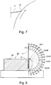
- the hardness of layers of material having so small thickness dimensions can hardly be measured through conventional methods of hardness determination, such as for example Vickers. But it is possible to get an apprehension about the hardness through comparative studies of the bending strength of tools of the invention and of conventionally manufactured tools. Fig.
- FIG. 8 shows schematically a simple device 12 used for such studies, which give clear and distinct proofs of the improvements of bending strength which have been achieved according to the invention. These results also imply an important progress in the technique which is based on the use of doctor and/or coater blades.
- the improvement of the bending strength is particularly significant as it is combined with a pronounced improvement of the wear resistance of the tool which has been evidenced through field tests.
- the degree of springback is a measure of the bending strength.
- underlying layers 7a, 7b which are harder than the base material of the body but not as hard as the surface layers but possibly thicker than them.
- the underlying layers 7a, 7b may be characterized as nitrified layers, i.e. layers of steel containing a high content of nitrides, i.e. compounds of nitrogen and nitride forming metals which may exist in the steel alloy.
- the nitrified layers 7a, 7b are established through Plasma Immersion Ion Implantation of nitrogen in a surface layer of the tool at a temperature which may be lower than the tempering temperature of the steel, before the very thin surface layers 6a, 6b which contain said hardness increasing products are established in a subsequent process.
- the nitrogen may be caused to diffuse deeper into the steel.
- the diffusion may be enhanced by using a strip steel which has a high content of nitride forming metals, such as chromium, molybdenum, titanium, zirconium, vanadium and/or tungsten and others, wherein the nitrogen may diffuse to a depth of at least 0.1 ⁇ m, preferably to at least 0.5 ⁇ m (500 nm) already at a temperature of about 300 °C.
- a thermal treatment at a temperature of up to 480 °C is conceivable in order to promote the diffusion of nitrogen to even greater depths and in any case to between at least 1 ⁇ m but not more than 10 ⁇ m, if so desired, but to maximum 30 % of the strip thickness, and thence also making the precipitation of metal nitrides in the steel more efficient. Therefore, in the nitride hardened layers 7a, 7b, the hardness may be increased with another 100-2500 HV-units (Hardness Vickers units) in excess of the base material's hardness of 500-700 HV.
- HV-units Hardness Vickers units
- the nitrided layers exhibit a hardness gradient counted from the surface layers, because the amount of nitrogen which has diffused into the steel successively is lower and lower in the direction of diffusion. At least in a zone of the nitrided layers, however, the hardness should amount to between 1000 and 3000 HV. In this connection should be mentioned that thicker nitrided layers than 30 % of the thickness of the strip are not desired, because that would cause that the tool 1, 2, 3, 4, which typically is very thin, could be too brittle.
- Fig. 6 schematically illustrates the result of the multi-step treatment.
- thin surface layers 6a', 6b' which form part of the initially nitride hardened layers, now very hard particles in the form of Me-nitrides, oxides, and/or carbides are precipitated, where Me represents nitride, oxide, and/or carbide forming metals.
- the said layers 7a and 7b which have a thickness of at least 0.1 ⁇ m (100 nm), preferably at least 0.5 ⁇ m 500), and suitably at least 1 ⁇ m (1000 nm), however not more than 30 % of the thickness of the strip, and which contain precipitated nitrides of a type and in an amount which afford said layers an additional hardness, so that they at least in a zone of the layers attain a hardness of between 1000 and 3000 HV.
- the nitriding such as it has been described above has two desired effects.
- the nitrided, comparatively thick layers 7a, 7b under the very thin surface layers 6a', 6b' form a support for the latter ones.
- very hard and very thin surface layers run a risk to be damaged if they rest like a thin skin directly on a much softer underlayer.
- the very hard but thin surface layers 6a', 6b' are supported by the not that hard but thicker layer 7a and 7b, respectively, which reduces said risk.
- the steel material 5 which is hardened and tempered to a hardness of between 500 and 700 HV.
- no thermal treatment of the nitrided layers 7a, 7b is performed before the surface layers 6a', 6 b' are applied.
- the Plasma Immersion Ion Implantation of the surface layers 6a', 6b' is performed at an elevated temperature near although lower than the tempering temperature of the steel and for so long period of time that the desired diffusion of nitrogen into the steel will be achieved during this phase.
- a thermal treatment of the nitrided layers is performed before the surface layers 6a', 6 b' are applied, whereupon an additional thermal treatment takes place during a Plasma Immersion Ion Implantation of the surface layers 6a', 6b' at an elevated temperature.
- Still another developed form of the invention is applicable in the cases when the strip steel is of a type which allows precipitation of secondary carbides, e.g. because the steel contains a substantial amount of retained austenite.
- cold rolled strip steels are hardened and tempered in a continuous process, which may cause some types of strip steel to contain a certain amount of retained austenite after hardening and tempering.
- the steel grades Sanprint (SANDVIK) and Uddeholm Hotvar, which are listed in Table 1, are examples of this type of steels which may make precipitation of secondary carbides during a second tempering operation possible, during which the retained austenite at least partly is transformed into secondary carbides and newly formed martenite.
- the hard surface layers 6a, 6b, Fig. 5 , or 6a', 6b', Fig. 6 may be coated with a sliding layer which reduces the friction against the roller, cylinder of corresponding which the doctor/coater blade is pressed against, e.g. a molybdenum layer which may be applied electrolytically according to any known technique, or a layer of Teflon (PTFE).
- a sliding layer which reduces the friction against the roller, cylinder of corresponding which the doctor/coater blade is pressed against, e.g. a molybdenum layer which may be applied electrolytically according to any known technique, or a layer of Teflon (PTFE).
- the microstructure of a sample of the surface treated strip material was studied by means of scanning electrone microscope.
- Fig. 9 shows the material greatly magnified.
- the lighter material a is the surface layer (designated 6a and 6b in the schematic drawing, Fig. 5 ), the thickness of which could be measured to about 350 nm.
- the microstructure of the base material b (designated 5 in Fig. 5 ), which contains major iron carbides minor carbides of not identified type, is visible under the surface layer.
- EDS energy-dispersive X-ray spectroscopy
- the result of the investigation is visualized as a spectrum, in which the area of the peaks are related to the amount of the different elements.
- the elements iron, chromium, manganese and silicon of the base material dominate.
- the reason why the test indicates so high content of the base elements may be that it cannot be avoided, due to the thinness of the surface layers, that also the underlying steel has influenced the test.
- the right hand image B shows that the surface layer has been enriched on these elements, which in the surface layer have been combined with carbon and/or nitrogen to form very small carbides, nitrides and/or carbonitrides, the presence of which could not be detected by scanning electron microscopy. Indirectly, however, the presence of these hard products could be registered through the remarkable increase of the wear resistance of the tool that was achieved.
- a doctor blade made in accordance with the invention of the surface treated strip material of the above mentioned steel grade was subjected to a comparative field test in a flexo printing machine with a ceramic ink transferring plate cylinder, which was laser beam engraved to a line density of 220 lines/cm.
- the plate cylinder had rotated a distance against the doctor blade according to the invention corresponding to about 2.2 x 10 6 running meters (2 200 000 metres)
- the doctor blade was considered to be worn out according to the criteria which were valid in that printing office.
- the purpose was to evaluate the importance of the duration of the treatment of the strip material in the furnace with reference to achieved springiness in terms of springback capacity of the doctor blade. It was judged that the bending test which has been described above with reference to Fig. 8 should be an adequate, comparative method for obtaining a comprehension about the importance of the duration of treatment.
- a first batch of strips, test A was therefor treated for 16 hours, while a second batch of strips of the same kind, test B, was treated for 30 hours but in other respects in the same mode as the first batch.
- the test also demonstrates that a prolonged duration of treatment, and thence probably an increased amount of hard products in the doctor blade material, gives a significant improvement of a feature which is very important for a strip shaped doctor blade, namely a high bending strength in combination with an adequate flexibility and ductility.
- the two materials were also studied in a scanning electron microscope and by means of energy-dispersive X-ray spectroscopy, EDS.
- the microscope-photographic images, Fig. 11 and Fig. 12 (after 16 and 30 hours treatment, respectively, in the Plasma Immersion Ion Implantation furnace), are made so that also the surface of the specimens on top of the surface layers are viewed.
- the darker parts represent the base material, i.e. the steel in the tool body under the surface layers.
- the thicknesses after 16 and 30 hours treatment were measured to about 320 nm and 590 nm, respectively.
- the EDS-analysis gave the same information as in Example 1, namely that Mo, V, and Cr were enriched in the surface layers.
- the hardness of the base material (body 5) was measured to 580 HV after 16 hours as well as after 30 hours of treatment.
- the microstructure of the surface layers could not be determined by means of scanning electron microscopy, but when applying atomic number contrast imaging, the layer which is farthest out, which is indicated by the upper arrow on the image, Fig. 13 , became dark.
- Under the darker layer one can discern a transition zone which is lighter and indicated by the lower arrow. It is assumed that this may indicate that this zone is enriched on the heavier doping metal molybdenum, and in that case probably in the form of M6C-carbides and/or -nitrides.
- the stratification implies that there has been established an outer, very hard zone, which contains i.a. extremely hard titanium-carbides and/ or -nitrides, and an inner, not as hard zone, which contains not so extremely hard molybdenum-carbides and/or -nitrides.
- an outer, very hard zone which contains i.a. extremely hard titanium-carbides and/ or -nitrides
- an inner, not as hard zone which contains not so extremely hard molybdenum-carbides and/or -nitrides.
- de-escalation or phasing out of hardness which is a desirable effect.
- Fig. 15 shows an atomic number contrast image of the same treated steel.
- Fig. 16 shows a section of the base material, which has a typically martensitic structure. Adjacent to needles of martensite Ma there are lamella of cementite Ce, which have been precipitated during the tempering of the steel, and also small tempering carbides X, which have been precipitated from existing retained austenite during the Plasma Immersion Ion Implantation treatment.
- Example 3 The same type of alloyed but not stainless tool steel was used as in Example 3. Also the pre-treatment of the strip material was the same; cold-rolling, hardening, and tempering. The strip which had been pre-treated in that way, was subjected, in two steps, to Plasma Immersion Ion Implantation treatment in the same furnace as according to the foregoing examples. In the two steps, the following parameters for the treatment in the furnace were applied: Step 1 Step 2 Pressure 4 x 10 -3 torr 4 x 10 -3 torr Temperature 400 °C 140 °C Duration of treatment 10 hours 16 hours Frequence 25 kHz 25 kHz Doping metal None Mo, Ti, Cr, B, B Gas N 2 N 2
- test sample sprung back 140°, Ex 4, Fig.8 .
- the two-step treatment thus provided a material, which had the best springiness of the tested materials, but a sample of this tool steel on the other hand had a comparatively good bending strength already in its normal condition, Ex 4N.
- the greatest improvement of the bending resistance was gained through the long term treatment of the stainless steel, Ex 2B, Fig. 8 .
Landscapes
- Chemical & Material Sciences (AREA)
- Engineering & Computer Science (AREA)
- Mechanical Engineering (AREA)
- Materials Engineering (AREA)
- Metallurgy (AREA)
- Organic Chemistry (AREA)
- Life Sciences & Earth Sciences (AREA)
- Health & Medical Sciences (AREA)
- Chemical Kinetics & Catalysis (AREA)
- Surgery (AREA)
- Forests & Forestry (AREA)
- Heart & Thoracic Surgery (AREA)
- Veterinary Medicine (AREA)
- Nuclear Medicine, Radiotherapy & Molecular Imaging (AREA)
- Thermal Sciences (AREA)
- Biomedical Technology (AREA)
- Physics & Mathematics (AREA)
- Medical Informatics (AREA)
- Molecular Biology (AREA)
- Animal Behavior & Ethology (AREA)
- General Health & Medical Sciences (AREA)
- Public Health (AREA)
- Crystallography & Structural Chemistry (AREA)
- Solid-Phase Diffusion Into Metallic Material Surfaces (AREA)
- Physical Vapour Deposition (AREA)
- Dry Development In Electrophotography (AREA)
- Cleaning In Electrography (AREA)
- Coating Apparatus (AREA)
- Paper (AREA)
- Rotary Presses (AREA)
- Cutting Tools, Boring Holders, And Turrets (AREA)
- Nonmetal Cutting Devices (AREA)
Claims (17)
- Streifenförmiges Werkzeug (1, 2, 3, 4), das zu der Art von Werkzeugen gehört, die flache, streifenförmige Abstreifmesser und Streichmesser umfasst, die aufweisen einen Körper (5) aus Stahl, der zu einer Art gehört, der zu der Gruppe der härtbaren Stähle gehört, die besteht aus Kohlenstoffstählen, niedriglegierten Stählen, legierten aber nicht Edelstählen, edlen, martensitischen Chromstählen, wobei der Körper aufweist
zwei flache Seiten, die durch eine harte Oberflächenschicht (6a, 6b) bedeckt sind, die einerseits eines oder mehrere der Elemente Stickstoff, Sauerstoff und Kohlenstoff und andererseits eines oder mehrere von mit diesen Elementen reaktiven Metallen enthält, und wenigstens einen Endabschnitt, der den funktionalen Teil des Werkzeugs während dessen Gebrauch darstellt, wobei das eine oder die mehreren der Elemente Stickstoff, Sauerstoff und Kohlenstoff und das eine oder die mehreren reaktiven Metalle, die eines oder mehrere der Metalle Titan, Wolfram, Chrom, Molybdän, Bor, Vanadium, Aluminium und Zirkonium umfassen, in den Oberflächenschichten als härtesteigernde Reaktionsprodukte vorliegen, umfassend Partikel aus wenigstens irgendeinem der Stoffe, die zu der Gruppe von Stoffen gehören, die besteht aus Titannitrid (TiN) und Aluminiumnitrid (AlN), Vanadiumkarbid (VC), Wolframkarbid (WC) und Chromkarbid (Cr3C2) und Zirkoniumoxid (ZrO2), Aluminiumoxid (Al2O3) und Chromoxid (Cr2O3), dadurch gekennzeichnet,
dass die harten Oberflächenschichten (6a', 6b') eine zweite, unterliegende Schicht (7a, 7b) bedecken, die Nitride enthält, die in der zweiten Schicht abgeschieden wurden, die Härte in wenigstens einer Zone der zweiten Schicht auf eine Härte erhöhend, die 100 - 1500 HV (Vickershärte) größer ist als die Härte des Stahlmaterials (5) unter der zweiten Schicht, und
dass die zweite, unterliegende Schicht (7a, 7b) eine Dicke von wenigstens 0,1 µm (100nm) aber nicht mehr als 10µm (0,010 mm) aufweist,
dass die zweiten, unterliegenden Schichten und die harten Oberflächenschichten Mikrostrukturen der Arten aufweisen, die durch Plasmaimmersionsionenimplantation von Stickstoff in das Stahlmaterial und anschließende Plasmaimmersionsionenimplantation von einem oder mehreren der reaktiven Metalle Titan, Wolfram, Chrom, Molybdän, Bor, Vanadium, Aluminium und Zirkonium zusammen mit einem oder mehreren der Elemente Stickstoff, Sauerstoff und Kohlenstoff in den Stahl erhältlich sind,
dass der Körper aus einem kaltgewalzten Streifen aus Stahl besteht, der gehärtet und angelassen ist auf eine Härte zwischen 500 und 700 HV (Vickershärte) in seinem gehärteten und angelassenen Zustand, und
dass der Körper eine Dicke zwischen 0,07 und 0,6 mm aufweist. - Werkzeug gemäß Anspruch 1, dadurch gekennzeichnet, dass wenigstens eine Zone der zweiten Schicht eine Härte zwischen 1000 und 3000 HV aufweist.
- Werkzeug gemäß Anspruch 1, dadurch gekennzeichnet, dass die zweite, unterliegende Schicht eine Dicke von wenigstens 0,5 µm (500nm) aber nicht mehr als 10µm (0,010 mm) aufweist.
- Werkzeug gemäß Anspruch 1, dadurch gekennzeichnet, dass die zweite, unterliegende Schicht (7a, 7b) eine Dicke von wenigstens 1 µm (1000nm) aber nicht mehr als 10µm (0,010 mm) aufweist.
- Werkzeug gemäß Anspruch 1, dadurch gekennzeichnet, dass die harten Oberflächenschichten (6a, 6b), die harte Produkte der Reaktion zwischen einerseits einem oder mehreren der Elemente Stickstoff, Sauerstoff und Kohlenstoff und andererseits einem oder mehreren Metallen enthalten, eine Dicke von wenigstens 100 nm (Nanometern), bevorzugt wenigstens 200 nm aufweisen.
- Werkzeug gemäß Anspruch 5, dadurch gekennzeichnet, dass die harten Oberflächenschichten eine Dicke von wenigstens 300 nm aufweisen.
- Werkzeug gemäß Anspruch 5 und 6, dadurch gekennzeichnet, dass wenigstens zwei Metalle in die harten Oberflächenschichten implantiert sind, einschließlich wenigstens eines ersten Metalls, das deutlich leichter ist als ein anderes, zweites Metall, d.h. eine deutlich geringere atomare Zahl als das zweite Metall aufweist, wobei das erste, leichtere Metall in einer äußeren Zone der harten Oberflächenschichten angereichert ist während das zweite, schwerere Metall in einer inneren Zone der harten Oberflächenschichten angereichert ist.
- Werkzeug gemäß Anspruch 7, dadurch gekennzeichnet, dass das erste, leichtere Metall irgendeines der Elemente Bor, Aluminium, Titan, Vanadium und Chrom ist während das das zweite, schwerere Metall irgendeines der Elemente Zirkonium, Niob, Molybdän, Tantal und Wolfram ist.
- Werkzeug gemäß Anspruch 7 und 8, dadurch gekennzeichnet, dass jede Zone eine Dicke von 0,1 - 1 µm aufweist.
- Werkzeug gemäß irgendeinem der vorstehenden Ansprüche, dadurch gekennzeichnet, dass der Stahlkörper des Werkzeugs zwischen den harten Oberflächenschichten eine überwiegend martensitische Struktur aufweist, die größere Aggregationen von abgeschiedenen Zementit und sehr kleine Karbidpartikel enthält.
- Werkzeug gemäß Anspruch 10, dadurch gekennzeichnet, dass das Zementit eine primäre Phase ist, die vor der Plasmaimmersionsionenimplantation abgeschieden wurde während wenigstens ein wesentlicher Abschnitt der sehr kleinen Karbidpartikel durch Transformation von Restaustenit während der Plasmaimmersionsionenimplantation abgeschieden wurden.
- Verfahren zur Herstellung eines klingenförmigen Werkzeugs (1, 2, 3, 4) gemäß Anspruch 1 durch Bereitstellen eines streifenförmigen Körpers (5) aus einem härtbaren Stahl, der kaltgewalzt, gehärtet und angelassen ist auf eine Härte zwischen 500 und 700 HV (Vickershärte), und weiterhin dadurch gekennzeichnet,
dass das Werkzeug durch Plasmaimmersionsionenimplantation von Stickstoff ohne irgendein begleitendes Dotierungsmaterial nitriert ist bei einer Temperatur unterhalb der Anlasstemperatur des Stahls, was Abscheidung von Nitriden in einer Schicht (7a, 7b) unterhalb der Oberfläche der flachen Seiten des Werkzeugs verursacht, und
dass eine Oberflächenschicht (6a', 6b') anschließend dazu gebracht wird, die nitrierte Schicht (7a, 7b) an den flachen Seiten des Werkzeugs zu bedecken, durch Plasmaimmersionsionenimplantation von einerseits einem oder mehreren der Elemente Stickstoff, Sauerstoff und Kohlenstoff und andererseits einem oder mehreren der Metalle Vanadium, Molybdän, Wolfram, Chrom, Zirkonium, Titan, Bor und Aluminium, wobei die Elemente und Metalle jeweils Reaktionsprodukte in dem Stahl bilden. - Verfahren gemäß Anspruch 12, dadurch gekennzeichnet, dass die anschließende Plasmaimmersionsionenimplantation bei einer Temperatur von 130°C oder höher durchgeführt wird, jedoch unterhalb der Anlasstemperatur des Stahls, was eine Wärmebehandlung der nitrierten Schicht verursacht für eine solch lange Dauer, dass Stickstoff dazu gebracht wird weiter in den Stahl zu diffundieren und Nitride in einem tieferen Level abgeschieden werden, so dass die unterliegenden Schichten (7a, 7b) daher eine Dicke von wenigstens 0,1 µm (100 nm), bevorzugt wenigstens 0,5 µm (500 nm) und geeigneter Weise wenigstens 1 µm (1000 nm), jedoch nicht mehr als 30% der Dicke des Werkzeugs erhalten.
- Verfahren gemäß Anspruch 12, dadurch gekennzeichnet, dass das Einführen der harten Produkte der Reaktion zwischen einerseits einem oder mehreren der Elemente Stickstoff, Sauerstoff und Kohlenstoff und andererseits einem oder mehreren der Metalle, die die Fähigkeit haben mit einem oder mehreren der Elemente zu reagieren, durch Plasmaimmersionsionenimplantation durchgeführt wird und veranlasst wird für eine so lange Dauer fortzudauern, dass die Reaktionsprodukte, deren Eindringtiefe mit der Dauer zusammenhängt, während der der Plasmaimmersionsionenimplantationsprozess stattfindet, in den Stahl eindringen werden zu einer Tiefe, die der Dicke der Oberflächenschicht von wenigstens 100 nm (Nanometer), bevorzugt wenigstens 200 nm entspricht.
- Verfahren gemäß Anspruch 12, dadurch gekennzeichnet, dass, wenn das Anfangsmaterial für die Plasmaimmersionsionenimplantation ein raffinierter, d.h. niedriglegierter Stahl in Form eines Streifens ist, der kaltgewalzt, gehärtet und angelassen wurde auf eine Härte zwischen 500 und 700 HBV, der Stahlstreifen für wenigstens zehn Stunden in einer Ofenatmosphäre mit einer Temperatur von 130 - 170 °C Plasmaimmersionsionenimplantation ausgesetzt wird.
- Verfahren gemäß Anspruch 12, dadurch gekennzeichnet, dass, wenn das Anfangsmaterial für die Plasmaimmersionsionenimplantation ein legierter, aber kein edler härtbarer Stahl in Form eines Streifens ist, der kaltgewalzt, gehärtet und angelassen wurde auf eine Härte zwischen 500 und 700 HV, der Stahlstreifen für wenigstens zehn Stunden in einer Ofenatmosphäre mit einer Temperatur von 200 - 400 °C Plasmaimmersionsionenimplantation ausgesetzt wird.
- Verfahren gemäß Anspruch 12, dadurch gekennzeichnet, dass, wenn das Anfangsmaterial für die Plasmaimmersionsionenimplantation ein edler härtbarer Chromstahl in Form eines Streifens ist, der kaltgewalzt, gehärtet und angelassen wurde auf eine Härte zwischen 500 und 700 HV, der Stahlstreifen für wenigstens zehn Stunden in einer Ofenatmosphäre mit einer Temperatur von 150 - 300 °C Plasmaimmersionsionenimplantation ausgesetzt wird.
Applications Claiming Priority (2)
| Application Number | Priority Date | Filing Date | Title |
|---|---|---|---|
| SE1100200 | 2011-03-18 | ||
| PCT/SE2012/050284 WO2012128700A1 (en) | 2011-03-18 | 2012-03-15 | Blade shaped tool and method for its manufacturing |
Publications (3)
| Publication Number | Publication Date |
|---|---|
| EP2686481A1 EP2686481A1 (de) | 2014-01-22 |
| EP2686481A4 EP2686481A4 (de) | 2014-11-19 |
| EP2686481B1 true EP2686481B1 (de) | 2017-07-12 |
Family
ID=46879610
Family Applications (1)
| Application Number | Title | Priority Date | Filing Date |
|---|---|---|---|
| EP12761451.9A Active EP2686481B1 (de) | 2011-03-18 | 2012-03-15 | Klingenförmiges werkzeug und verfahren zu seiner herstellung |
Country Status (7)
| Country | Link |
|---|---|
| US (1) | US20140000467A1 (de) |
| EP (1) | EP2686481B1 (de) |
| JP (1) | JP2014518529A (de) |
| KR (1) | KR20140014242A (de) |
| CN (1) | CN103518018A (de) |
| BR (1) | BR112013023765A2 (de) |
| WO (1) | WO2012128700A1 (de) |
Cited By (1)
| Publication number | Priority date | Publication date | Assignee | Title |
|---|---|---|---|---|
| RU2685890C1 (ru) * | 2018-05-08 | 2019-04-23 | федеральное государственное бюджетное образовательное учреждение высшего образования "Уфимский государственный авиационный технический университет" | Способ упрочняющей обработки лопаток блиска из легированных сталей |
Families Citing this family (12)
| Publication number | Priority date | Publication date | Assignee | Title |
|---|---|---|---|---|
| DE102012106351B4 (de) * | 2012-07-13 | 2015-11-19 | C. & E. Fein Gmbh | Sägeblatt oder Trennschleifblatt aus martensitischem Edelstahl oder Stahl sowie Verfahren zu dessen Herstellung |
| DE102013205597A1 (de) * | 2013-03-28 | 2014-10-02 | Voith Patent Gmbh | Schaber |
| EP2896714B1 (de) | 2014-01-17 | 2016-04-13 | voestalpine Precision Strip AB | Kreppschaber und Verfahren zu seiner Herstellung |
| DK178658B1 (da) * | 2015-02-04 | 2016-10-17 | Tresu As | Kammerrakel |
| EP3165367A1 (de) | 2015-11-04 | 2017-05-10 | BTG Eclépens S.A. | Rakel, farbwerkanordnung und verwendung der rakel beim flexodruck |
| CN108342708B (zh) * | 2018-03-22 | 2020-08-07 | 深圳大学 | 一种碳元素注入方法及其改性刀具、模具 |
| CN108532352B (zh) | 2018-03-26 | 2024-03-29 | 赣州恩创科技有限公司 | 一种起皱刀及其制备方法 |
| RU2685888C1 (ru) * | 2018-05-08 | 2019-04-23 | федеральное государственное бюджетное образовательное учреждение высшего образования "Уфимский государственный авиационный технический университет" | Способ упрочнения лопаток моноколеса из титановых сплавов |
| CN110042342A (zh) * | 2019-04-23 | 2019-07-23 | 杭州阿牟文化艺术有限公司 | 一种耐蚀型刀剪材料的制备方法 |
| CN112160184A (zh) * | 2020-10-11 | 2021-01-01 | 杭州天朗金属科技有限公司 | 一种镀膜起皱刮刀及其制备方法 |
| WO2024157043A1 (en) | 2023-01-23 | 2024-08-02 | Aikawa Fiber Technologies Oy | Screen cylinder with bars configured to receive a wear resistant spray coating |
| CN116855910A (zh) * | 2023-07-13 | 2023-10-10 | 中浙高铁轴承有限公司 | 一种高铁轴承用Ti-V-W-N薄膜的制备方法 |
Family Cites Families (14)
| Publication number | Priority date | Publication date | Assignee | Title |
|---|---|---|---|---|
| US3988955A (en) * | 1972-12-14 | 1976-11-02 | Engel Niels N | Coated steel product and process of producing the same |
| US4653373A (en) * | 1986-01-08 | 1987-03-31 | Gerber Scientific Inc. | Knife blade and method for making same |
| AT394680B (de) * | 1988-02-03 | 1992-05-25 | Boehler Gmbh | Linien- schneidmesser fuer die bearbeitung von flaechigem material |
| ATE220992T1 (de) * | 1997-10-08 | 2002-08-15 | Rolf Meyer | Druckrakel und verfahren zur herstellung derselben |
| FI980884L (fi) * | 1998-04-22 | 1999-10-23 | Valmet Corp | Paperi-/kartonki- tai jälkikäsittelykoneen osat, jotka joutuvat suuren kulutuksen kohteeksi ja menetelmä näiden osien valmistamiseksi |
| DE19840950A1 (de) * | 1998-09-08 | 2000-03-09 | Jagenberg Papiertech Gmbh | Messer zum Schneiden laufender Materialbahnen |
| US20050100673A1 (en) * | 2002-05-22 | 2005-05-12 | Ulrich Schoof | Method for the surface treatment of a doctor element |
| SE526501C2 (sv) * | 2003-01-13 | 2005-09-27 | Sandvik Intellectual Property | Metod för att ytmodifiera ett utskiljningshärdat rostfritt stål |
| SE527180C2 (sv) * | 2003-08-12 | 2006-01-17 | Sandvik Intellectual Property | Rakel- eller schaberblad med nötningsbeständigt skikt samt metod för tillverkning därav |
| SE526191C2 (sv) * | 2003-12-19 | 2005-07-26 | Sandvik Ab | Eggförsett verktyg och metod för framställning därav |
| DE102004034905A1 (de) * | 2004-07-19 | 2006-04-13 | Böhler-Uddeholm Precision Strip GmbH & Co. KG | Stahlband für Streichmesser, Auftragsmesser und Kreppschaber und pulvermetallurgisches Verfahren zu ihrer Herstellung |
| US8058156B2 (en) * | 2004-07-20 | 2011-11-15 | Applied Materials, Inc. | Plasma immersion ion implantation reactor having multiple ion shower grids |
| EP2042261A3 (de) * | 2007-09-26 | 2015-02-18 | Sandvik Intellectual Property AB | Verfahren zur Herstellung eines beschichteten Schneidwerkzeugs |
| FI121793B (fi) * | 2009-06-05 | 2011-04-15 | Metso Minerals Inc | Menetelmä kulutusosan pinnoittamiseksi, menetelmällä pinnoitetun kulutusosan käyttö, kulutusosa ja jauhin |
-
2012
- 2012-03-15 BR BR112013023765A patent/BR112013023765A2/pt not_active IP Right Cessation
- 2012-03-15 EP EP12761451.9A patent/EP2686481B1/de active Active
- 2012-03-15 KR KR1020137027556A patent/KR20140014242A/ko not_active Withdrawn
- 2012-03-15 JP JP2013558817A patent/JP2014518529A/ja active Pending
- 2012-03-15 WO PCT/SE2012/050284 patent/WO2012128700A1/en not_active Ceased
- 2012-03-15 US US14/004,059 patent/US20140000467A1/en not_active Abandoned
- 2012-03-15 CN CN201280022665.1A patent/CN103518018A/zh active Pending
Non-Patent Citations (1)
| Title |
|---|
| None * |
Cited By (1)
| Publication number | Priority date | Publication date | Assignee | Title |
|---|---|---|---|---|
| RU2685890C1 (ru) * | 2018-05-08 | 2019-04-23 | федеральное государственное бюджетное образовательное учреждение высшего образования "Уфимский государственный авиационный технический университет" | Способ упрочняющей обработки лопаток блиска из легированных сталей |
Also Published As
| Publication number | Publication date |
|---|---|
| CN103518018A (zh) | 2014-01-15 |
| JP2014518529A (ja) | 2014-07-31 |
| US20140000467A1 (en) | 2014-01-02 |
| BR112013023765A2 (pt) | 2017-02-07 |
| WO2012128700A1 (en) | 2012-09-27 |
| EP2686481A4 (de) | 2014-11-19 |
| KR20140014242A (ko) | 2014-02-05 |
| EP2686481A1 (de) | 2014-01-22 |
Similar Documents
| Publication | Publication Date | Title |
|---|---|---|
| EP2686481B1 (de) | Klingenförmiges werkzeug und verfahren zu seiner herstellung | |
| Kumar et al. | Friction and tribological behavior of bare nitrided, TiAlN and AlCrN coated MDC-K hot work tool steel | |
| Taktak | Some mechanical properties of borided AISI H13 and 304 steels | |
| Rousseau et al. | Microstructural and tribological characterisation of a nitriding/TiAlN PVD coating duplex treatment applied to M2 High Speed Steel tools | |
| US20080261058A1 (en) | Coated cutting tool, cutting member or wear part | |
| Günen et al. | High temperature wear behavior of the surface-modified externally cooled rolls | |
| EP4194571A1 (de) | Stahlplatte | |
| EP4560038A1 (de) | Hochfestes stahlblech, verfahren zur herstellung davon, element und verfahren zur herstellung davon | |
| JP7564510B2 (ja) | 表面被覆切削工具 | |
| CN100540710C (zh) | 用于刮刀刀片、涂层刮板和起皱刮刀的钢带及其粉末冶金制造方法 | |
| Novák et al. | Wear and corrosion resistance of a plasma-nitrided PM tool steel alloyed with niobium | |
| Li et al. | Microstructure and corrosion resistance of nitrogen-rich surface layers on AISI 304 stainless steel by rapid nitriding in a hollow cathode discharge | |
| EP3181729A1 (de) | Hartbeschichtung und matrize | |
| CZ413297A3 (cs) | Základní materiál pro výrobu základních listů pro kotoučové pily, řezací kotouče, rámové pily, jakož i řezací a škrabací zařízení | |
| EP1900849B1 (de) | Zementierte Karbideinsätze zum Fräsen harter Eisenlegierungen > 45 HRC | |
| US10233530B2 (en) | Hard film and method for forming same, and die for use in hot forming of steel sheet | |
| Gammer et al. | Investigations on the effects of plasma-assisted pre-treatment for plasma-assisted chemical vapour deposition TiN coatings on tool steel | |
| Akao et al. | Surface modification of cold-working die steel by electron beam irradiation–formation of cemented carbide composite layer | |
| EP2316984A1 (de) | Hartfolie, Kunststoffverarbeitungsdüse, Kunststoffverarbeitungsverfahren und Ziel für Hartfolie | |
| Wierzchoń et al. | Properties of multicomponent surface layers produced on steels by modified plasma nitriding processes | |
| EP4194191A1 (de) | Stahlblech | |
| Ashvita et al. | Comparative study on surface modification of heat-treated hot work tool steel using plasma nitriding and thin film deposition technique | |
| Novák et al. | Pulsed-plasma nitriding of a niobium–alloyed PM tool steel | |
| KR20140104172A (ko) | 절삭 공구의 내마모성 향상방법 및 이에 따라 내마모성이 향상된 절삭 공구 | |
| Smirnov et al. | Mixed-surface impregnation of gear wheels made of 13Kh3N3M2VFB-Sh age-hardenable integrally alloyed steel aimed at improving surface hardness, wear-resistance, and back-to-back endurance |
Legal Events
| Date | Code | Title | Description |
|---|---|---|---|
| PUAI | Public reference made under article 153(3) epc to a published international application that has entered the european phase |
Free format text: ORIGINAL CODE: 0009012 |
|
| 17P | Request for examination filed |
Effective date: 20130830 |
|
| AK | Designated contracting states |
Kind code of ref document: A1 Designated state(s): AL AT BE BG CH CY CZ DE DK EE ES FI FR GB GR HR HU IE IS IT LI LT LU LV MC MK MT NL NO PL PT RO RS SE SI SK SM TR |
|
| DAX | Request for extension of the european patent (deleted) | ||
| A4 | Supplementary search report drawn up and despatched |
Effective date: 20141020 |
|
| RIC1 | Information provided on ipc code assigned before grant |
Ipc: D21H 23/34 20060101ALI20141014BHEP Ipc: B41N 10/00 20060101ALI20141014BHEP Ipc: C23C 14/48 20060101ALI20141014BHEP Ipc: B26B 9/00 20060101ALI20141014BHEP Ipc: D21G 3/00 20060101AFI20141014BHEP Ipc: B23D 35/00 20060101ALI20141014BHEP Ipc: B05C 11/04 20060101ALI20141014BHEP Ipc: B41F 9/10 20060101ALI20141014BHEP Ipc: B31F 1/14 20060101ALI20141014BHEP |
|
| GRAP | Despatch of communication of intention to grant a patent |
Free format text: ORIGINAL CODE: EPIDOSNIGR1 |
|
| STAA | Information on the status of an ep patent application or granted ep patent |
Free format text: STATUS: GRANT OF PATENT IS INTENDED |
|
| INTG | Intention to grant announced |
Effective date: 20170203 |
|
| RAP1 | Party data changed (applicant data changed or rights of an application transferred) |
Owner name: PRIMEBLADE SWEDEN AB |
|
| RIN1 | Information on inventor provided before grant (corrected) |
Inventor name: LUNERFJORD, ALAN |
|
| GRAS | Grant fee paid |
Free format text: ORIGINAL CODE: EPIDOSNIGR3 |
|
| GRAA | (expected) grant |
Free format text: ORIGINAL CODE: 0009210 |
|
| STAA | Information on the status of an ep patent application or granted ep patent |
Free format text: STATUS: THE PATENT HAS BEEN GRANTED |
|
| AK | Designated contracting states |
Kind code of ref document: B1 Designated state(s): AL AT BE BG CH CY CZ DE DK EE ES FI FR GB GR HR HU IE IS IT LI LT LU LV MC MK MT NL NO PL PT RO RS SE SI SK SM TR |
|
| REG | Reference to a national code |
Ref country code: GB Ref legal event code: FG4D |
|
| RIN1 | Information on inventor provided before grant (corrected) |
Inventor name: LUNERFJORD, ALAN |
|
| REG | Reference to a national code |
Ref country code: CH Ref legal event code: EP |
|
| REG | Reference to a national code |
Ref country code: AT Ref legal event code: REF Ref document number: 908440 Country of ref document: AT Kind code of ref document: T Effective date: 20170715 |
|
| REG | Reference to a national code |
Ref country code: IE Ref legal event code: FG4D |
|
| REG | Reference to a national code |
Ref country code: DE Ref legal event code: R096 Ref document number: 602012034456 Country of ref document: DE |
|
| REG | Reference to a national code |
Ref country code: SE Ref legal event code: TRGR |
|
| REG | Reference to a national code |
Ref country code: NL Ref legal event code: MP Effective date: 20170712 |
|
| REG | Reference to a national code |
Ref country code: LT Ref legal event code: MG4D |
|
| REG | Reference to a national code |
Ref country code: AT Ref legal event code: MK05 Ref document number: 908440 Country of ref document: AT Kind code of ref document: T Effective date: 20170712 |
|
| PG25 | Lapsed in a contracting state [announced via postgrant information from national office to epo] |
Ref country code: LT Free format text: LAPSE BECAUSE OF FAILURE TO SUBMIT A TRANSLATION OF THE DESCRIPTION OR TO PAY THE FEE WITHIN THE PRESCRIBED TIME-LIMIT Effective date: 20170712 Ref country code: AT Free format text: LAPSE BECAUSE OF FAILURE TO SUBMIT A TRANSLATION OF THE DESCRIPTION OR TO PAY THE FEE WITHIN THE PRESCRIBED TIME-LIMIT Effective date: 20170712 Ref country code: NO Free format text: LAPSE BECAUSE OF FAILURE TO SUBMIT A TRANSLATION OF THE DESCRIPTION OR TO PAY THE FEE WITHIN THE PRESCRIBED TIME-LIMIT Effective date: 20171012 Ref country code: NL Free format text: LAPSE BECAUSE OF FAILURE TO SUBMIT A TRANSLATION OF THE DESCRIPTION OR TO PAY THE FEE WITHIN THE PRESCRIBED TIME-LIMIT Effective date: 20170712 Ref country code: HR Free format text: LAPSE BECAUSE OF FAILURE TO SUBMIT A TRANSLATION OF THE DESCRIPTION OR TO PAY THE FEE WITHIN THE PRESCRIBED TIME-LIMIT Effective date: 20170712 Ref country code: FI Free format text: LAPSE BECAUSE OF FAILURE TO SUBMIT A TRANSLATION OF THE DESCRIPTION OR TO PAY THE FEE WITHIN THE PRESCRIBED TIME-LIMIT Effective date: 20170712 |
|
| PG25 | Lapsed in a contracting state [announced via postgrant information from national office to epo] |
Ref country code: PL Free format text: LAPSE BECAUSE OF FAILURE TO SUBMIT A TRANSLATION OF THE DESCRIPTION OR TO PAY THE FEE WITHIN THE PRESCRIBED TIME-LIMIT Effective date: 20170712 Ref country code: RS Free format text: LAPSE BECAUSE OF FAILURE TO SUBMIT A TRANSLATION OF THE DESCRIPTION OR TO PAY THE FEE WITHIN THE PRESCRIBED TIME-LIMIT Effective date: 20170712 Ref country code: ES Free format text: LAPSE BECAUSE OF FAILURE TO SUBMIT A TRANSLATION OF THE DESCRIPTION OR TO PAY THE FEE WITHIN THE PRESCRIBED TIME-LIMIT Effective date: 20170712 Ref country code: BG Free format text: LAPSE BECAUSE OF FAILURE TO SUBMIT A TRANSLATION OF THE DESCRIPTION OR TO PAY THE FEE WITHIN THE PRESCRIBED TIME-LIMIT Effective date: 20171012 Ref country code: LV Free format text: LAPSE BECAUSE OF FAILURE TO SUBMIT A TRANSLATION OF THE DESCRIPTION OR TO PAY THE FEE WITHIN THE PRESCRIBED TIME-LIMIT Effective date: 20170712 Ref country code: GR Free format text: LAPSE BECAUSE OF FAILURE TO SUBMIT A TRANSLATION OF THE DESCRIPTION OR TO PAY THE FEE WITHIN THE PRESCRIBED TIME-LIMIT Effective date: 20171013 Ref country code: IS Free format text: LAPSE BECAUSE OF FAILURE TO SUBMIT A TRANSLATION OF THE DESCRIPTION OR TO PAY THE FEE WITHIN THE PRESCRIBED TIME-LIMIT Effective date: 20171112 |
|
| REG | Reference to a national code |
Ref country code: FR Ref legal event code: PLFP Year of fee payment: 7 |
|
| REG | Reference to a national code |
Ref country code: DE Ref legal event code: R097 Ref document number: 602012034456 Country of ref document: DE |
|
| PG25 | Lapsed in a contracting state [announced via postgrant information from national office to epo] |
Ref country code: DK Free format text: LAPSE BECAUSE OF FAILURE TO SUBMIT A TRANSLATION OF THE DESCRIPTION OR TO PAY THE FEE WITHIN THE PRESCRIBED TIME-LIMIT Effective date: 20170712 Ref country code: RO Free format text: LAPSE BECAUSE OF FAILURE TO SUBMIT A TRANSLATION OF THE DESCRIPTION OR TO PAY THE FEE WITHIN THE PRESCRIBED TIME-LIMIT Effective date: 20170712 Ref country code: CZ Free format text: LAPSE BECAUSE OF FAILURE TO SUBMIT A TRANSLATION OF THE DESCRIPTION OR TO PAY THE FEE WITHIN THE PRESCRIBED TIME-LIMIT Effective date: 20170712 |
|
| PLBE | No opposition filed within time limit |
Free format text: ORIGINAL CODE: 0009261 |
|
| STAA | Information on the status of an ep patent application or granted ep patent |
Free format text: STATUS: NO OPPOSITION FILED WITHIN TIME LIMIT |
|
| PG25 | Lapsed in a contracting state [announced via postgrant information from national office to epo] |
Ref country code: SM Free format text: LAPSE BECAUSE OF FAILURE TO SUBMIT A TRANSLATION OF THE DESCRIPTION OR TO PAY THE FEE WITHIN THE PRESCRIBED TIME-LIMIT Effective date: 20170712 Ref country code: EE Free format text: LAPSE BECAUSE OF FAILURE TO SUBMIT A TRANSLATION OF THE DESCRIPTION OR TO PAY THE FEE WITHIN THE PRESCRIBED TIME-LIMIT Effective date: 20170712 Ref country code: SK Free format text: LAPSE BECAUSE OF FAILURE TO SUBMIT A TRANSLATION OF THE DESCRIPTION OR TO PAY THE FEE WITHIN THE PRESCRIBED TIME-LIMIT Effective date: 20170712 |
|
| 26N | No opposition filed |
Effective date: 20180413 |
|
| PG25 | Lapsed in a contracting state [announced via postgrant information from national office to epo] |
Ref country code: SI Free format text: LAPSE BECAUSE OF FAILURE TO SUBMIT A TRANSLATION OF THE DESCRIPTION OR TO PAY THE FEE WITHIN THE PRESCRIBED TIME-LIMIT Effective date: 20170712 |
|
| PG25 | Lapsed in a contracting state [announced via postgrant information from national office to epo] |
Ref country code: MC Free format text: LAPSE BECAUSE OF FAILURE TO SUBMIT A TRANSLATION OF THE DESCRIPTION OR TO PAY THE FEE WITHIN THE PRESCRIBED TIME-LIMIT Effective date: 20170712 |
|
| REG | Reference to a national code |
Ref country code: BE Ref legal event code: MM Effective date: 20180331 |
|
| REG | Reference to a national code |
Ref country code: IE Ref legal event code: MM4A |
|
| PG25 | Lapsed in a contracting state [announced via postgrant information from national office to epo] |
Ref country code: LU Free format text: LAPSE BECAUSE OF NON-PAYMENT OF DUE FEES Effective date: 20180315 |
|
| PG25 | Lapsed in a contracting state [announced via postgrant information from national office to epo] |
Ref country code: IE Free format text: LAPSE BECAUSE OF NON-PAYMENT OF DUE FEES Effective date: 20180315 |
|
| PG25 | Lapsed in a contracting state [announced via postgrant information from national office to epo] |
Ref country code: BE Free format text: LAPSE BECAUSE OF NON-PAYMENT OF DUE FEES Effective date: 20180331 |
|
| PG25 | Lapsed in a contracting state [announced via postgrant information from national office to epo] |
Ref country code: MT Free format text: LAPSE BECAUSE OF NON-PAYMENT OF DUE FEES Effective date: 20180315 |
|
| PG25 | Lapsed in a contracting state [announced via postgrant information from national office to epo] |
Ref country code: TR Free format text: LAPSE BECAUSE OF FAILURE TO SUBMIT A TRANSLATION OF THE DESCRIPTION OR TO PAY THE FEE WITHIN THE PRESCRIBED TIME-LIMIT Effective date: 20170712 |
|
| PG25 | Lapsed in a contracting state [announced via postgrant information from national office to epo] |
Ref country code: PT Free format text: LAPSE BECAUSE OF FAILURE TO SUBMIT A TRANSLATION OF THE DESCRIPTION OR TO PAY THE FEE WITHIN THE PRESCRIBED TIME-LIMIT Effective date: 20170712 Ref country code: HU Free format text: LAPSE BECAUSE OF FAILURE TO SUBMIT A TRANSLATION OF THE DESCRIPTION OR TO PAY THE FEE WITHIN THE PRESCRIBED TIME-LIMIT; INVALID AB INITIO Effective date: 20120315 |
|
| PG25 | Lapsed in a contracting state [announced via postgrant information from national office to epo] |
Ref country code: CY Free format text: LAPSE BECAUSE OF FAILURE TO SUBMIT A TRANSLATION OF THE DESCRIPTION OR TO PAY THE FEE WITHIN THE PRESCRIBED TIME-LIMIT Effective date: 20170712 Ref country code: MK Free format text: LAPSE BECAUSE OF NON-PAYMENT OF DUE FEES Effective date: 20170712 |
|
| PG25 | Lapsed in a contracting state [announced via postgrant information from national office to epo] |
Ref country code: AL Free format text: LAPSE BECAUSE OF FAILURE TO SUBMIT A TRANSLATION OF THE DESCRIPTION OR TO PAY THE FEE WITHIN THE PRESCRIBED TIME-LIMIT Effective date: 20170712 |
|
| PGFP | Annual fee paid to national office [announced via postgrant information from national office to epo] |
Ref country code: DE Payment date: 20240319 Year of fee payment: 13 Ref country code: GB Payment date: 20240318 Year of fee payment: 13 |
|
| PGFP | Annual fee paid to national office [announced via postgrant information from national office to epo] |
Ref country code: IT Payment date: 20240321 Year of fee payment: 13 Ref country code: FR Payment date: 20240315 Year of fee payment: 13 |
|
| PGFP | Annual fee paid to national office [announced via postgrant information from national office to epo] |
Ref country code: CH Payment date: 20240401 Year of fee payment: 13 |
|
| REG | Reference to a national code |
Ref country code: DE Ref legal event code: R119 Ref document number: 602012034456 Country of ref document: DE |
|
| REG | Reference to a national code |
Ref country code: CH Ref legal event code: H13 Free format text: ST27 STATUS EVENT CODE: U-0-0-H10-H13 (AS PROVIDED BY THE NATIONAL OFFICE) Effective date: 20251023 |
|
| GBPC | Gb: european patent ceased through non-payment of renewal fee |
Effective date: 20250315 |
|
| PG25 | Lapsed in a contracting state [announced via postgrant information from national office to epo] |
Ref country code: DE Free format text: LAPSE BECAUSE OF NON-PAYMENT OF DUE FEES Effective date: 20251001 |
|
| PG25 | Lapsed in a contracting state [announced via postgrant information from national office to epo] |
Ref country code: GB Free format text: LAPSE BECAUSE OF NON-PAYMENT OF DUE FEES Effective date: 20250315 |
|
| PG25 | Lapsed in a contracting state [announced via postgrant information from national office to epo] |
Ref country code: FR Free format text: LAPSE BECAUSE OF NON-PAYMENT OF DUE FEES Effective date: 20250331 Ref country code: IT Free format text: LAPSE BECAUSE OF NON-PAYMENT OF DUE FEES Effective date: 20250315 |
|
| PG25 | Lapsed in a contracting state [announced via postgrant information from national office to epo] |
Ref country code: CH Free format text: LAPSE BECAUSE OF NON-PAYMENT OF DUE FEES Effective date: 20250331 |
|
| PGFP | Annual fee paid to national office [announced via postgrant information from national office to epo] |
Ref country code: SE Payment date: 20260320 Year of fee payment: 15 |